DG8SAQ VNWA 3 & 3E - Vector Network Analyzer - SDR-Kits
DG8SAQ VNWA 3 & 3E - Vector Network Analyzer - SDR-Kits
DG8SAQ VNWA 3 & 3E - Vector Network Analyzer - SDR-Kits

You also want an ePaper? Increase the reach of your titles
YUMPU automatically turns print PDFs into web optimized ePapers that Google loves.
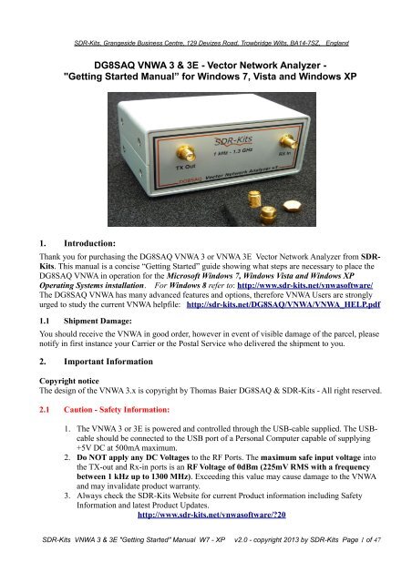
<strong>SDR</strong>-<strong>Kits</strong>, Grangeside Business Centre, 129 Devizes Road, Trowbridge Wilts, BA14-7SZ, England<br />
<strong>DG8SAQ</strong> <strong>VNWA</strong> 3 & <strong>3E</strong> - <strong>Vector</strong> <strong>Network</strong> <strong>Analyzer</strong> -<br />
"Getting Started Manual” for Windows 7, Vista and Windows XP<br />
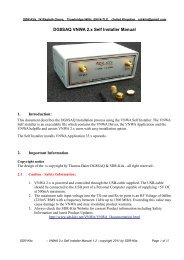
1. Introduction:<br />
Thank you for purchasing the <strong>DG8SAQ</strong> <strong>VNWA</strong> 3 or <strong>VNWA</strong> <strong>3E</strong> <strong>Vector</strong> <strong>Network</strong> <strong>Analyzer</strong> from <strong>SDR</strong>-<br />
<strong>Kits</strong>. This manual is a concise “Getting Started” guide showing what steps are necessary to place the<br />
<strong>DG8SAQ</strong> <strong>VNWA</strong> in operation for the Microsoft Windows 7, Windows Vista and Windows XP<br />
Operating Systems installation. For Windows 8 refer to: http://www.sdr-kits.net/vnwasoftware/<br />
The <strong>DG8SAQ</strong> <strong>VNWA</strong> has many advanced features and options, therefore <strong>VNWA</strong> Users are strongly<br />
urged to study the current <strong>VNWA</strong> helpfile: http://sdr-kits.net/<strong>DG8SAQ</strong>/<strong>VNWA</strong>/<strong>VNWA</strong>_HELP.pdf<br />
1.1 Shipment Damage:<br />
You should receive the <strong>VNWA</strong> in good order, however in event of visible damage of the parcel, please<br />
notify in first instance your Carrier or the Postal Service who delivered the shipment to you.<br />
2. Important Information<br />
Copyright notice<br />
The design of the <strong>VNWA</strong> 3.x is copyright by Thomas Baier <strong>DG8SAQ</strong> & <strong>SDR</strong>-<strong>Kits</strong> - All right reserved.<br />
2.1 Caution - Safety Information:<br />
1. The <strong>VNWA</strong> 3 or <strong>3E</strong> is powered and controlled through the USB-cable supplied. The USBcable<br />
should be connected to the USB port of a Personal Computer capable of supplying<br />
+5V DC at 500mA maximum.<br />
2. Do NOT apply any DC Voltages to the RF Ports. The maximum safe input voltage into<br />
the TX-out and Rx-in ports is an RF Voltage of 0dBm (225mV RMS with a frequency<br />
between 1 kHz up to 1300 MHz). Exceeding this value may cause damage to the <strong>VNWA</strong><br />
and may invalidate product warranty.<br />
3. Always check the <strong>SDR</strong>-<strong>Kits</strong> Website for current Product information including Safety<br />
Information and latest Product Updates.<br />
http://www.sdr-kits.net/vnwasoftware/20<br />
<strong>SDR</strong>-<strong>Kits</strong> <strong>VNWA</strong> 3 & <strong>3E</strong> "Getting Started" Manual W7 - XP v2.0 - copyright 2013 by <strong>SDR</strong>-<strong>Kits</strong> Page 1 of 47
2. 2 Accuracy of Measurements<br />
This product is designed for Educational, Amateur Radio and Hobbyist use. No warranties are made<br />
whatsoever as to the stability and suitability of the design in extended periods/continuous operation or<br />
operation outside components’ specifications. No responsibility will be accepted for accuracy of<br />
measurements or performance either short term or long term. It is recommended that <strong>VNWA</strong> users<br />
check proper operation of <strong>VNWA</strong> at regular intervals by measuring parameters of components after<br />
performing <strong>VNWA</strong> calibration.<br />
2.3 <strong>VNWA</strong> 3 and <strong>VNWA</strong> <strong>3E</strong> - Product Documentation:<br />
The documentation of the <strong>VNWA</strong> 3 is supplied as a <strong>VNWA</strong> Application Helpfile, which is available<br />
when the <strong>VNWA</strong> Application is installed using the <strong>VNWA</strong> Installer. A PDF version of this help file<br />
may be downloaded from the Internet from http://sdr-kits.net/<strong>DG8SAQ</strong>/<strong>VNWA</strong>/<strong>VNWA</strong>_HELP.pdf<br />
Note: The <strong>VNWA</strong> <strong>3E</strong> is a <strong>VNWA</strong> 3 with the optional <strong>VNWA</strong> Expansion board containing a second<br />
Audio Codec fitted. This Booklet shows configuration of both <strong>VNWA</strong> <strong>3E</strong> and <strong>VNWA</strong> 3. Note that a<br />
few steps in the <strong>VNWA</strong> Application setup procedure are only required for <strong>VNWA</strong> <strong>3E</strong>.<br />
2.4 <strong>VNWA</strong> License code:<br />
The <strong>VNWA</strong> License code for your <strong>VNWA</strong> is shown below:<br />
The license code must be entered exactly as shown in step 3.1.6 (Win7 or Vista) or in step 3.3.5 (XP)<br />
Axxxx:ABC-DE-FGH-IJK:<br />
Note: Optionally the name of the <strong>VNWA</strong> user may be added after the <strong>VNWA</strong> license code within<br />
double quotes:<br />
for example: A1999:kzl-blt-qua-lzt:”<strong>DG8SAQ</strong>”<br />
The <strong>VNWA</strong> application will now display the <strong>VNWA</strong> serial number (A1999) and the <strong>VNWA</strong> User name<br />
as<br />
<strong>Vector</strong> <strong>Network</strong> <strong>Analyzer</strong> Software - A1999 licensed to <strong>DG8SAQ</strong><br />
3. <strong>VNWA</strong> Driver - Software and Helpfile Installation<br />
Caution: Although the installation package is provided for easy installation, it is recommended that<br />
the appropriate installation procedure for your Operating System is reviewed before starting the<br />
installer. The procedure below assumes that <strong>VNWA</strong> package has NOT been installed previously on the<br />
Computer in question.<br />
Please email: Support@<strong>SDR</strong>-<strong>Kits</strong>.net to report any errors or improvements to this document – Thanks<br />
3.1 Windows 7 & Vista 64 bit and 32 bit Installation<br />
This section shows installation procedure for Windows 7 (64 or 32 bits) – Vista procedure is similar.<br />
Note: For Installation on Windows XP refer to Section 3.3<br />
IMPORTANT: Information for Windows 7 and Vista users:<br />
<strong>SDR</strong>-<strong>Kits</strong> <strong>VNWA</strong> 3 & <strong>3E</strong> "Getting Started" Manual W7 - XP v2.0 - copyright 2013 by <strong>SDR</strong>-<strong>Kits</strong> Page 2 of 47
If you are installing the <strong>VNWA</strong> application for the first time, the <strong>VNWA</strong> Setup program will guide you<br />
to install an application Winhlp32.exe from the Microsoft website. The Winhlp32.exe program is<br />
required to display the <strong>VNWA</strong> help file. However Microsoft license conditions does not allow the<br />
Winhelp32.exe to be distributed as part of the <strong>VNWA</strong> setup program.<br />
<strong>VNWA</strong> installation is easier and friendlier if Winhlp32.exe application is already installed beforehand.<br />
It is therefore recommend to install Winhlp32.exe from the link:<br />
http://support.microsoft.com/kb/917607 prior to starting the <strong>VNWA</strong> installation program.<br />
You can always check if Winhlp32.exe is already installed by inspecting the file size of this file in<br />
C:\windows. If file size of Winhlp32.exe is 290 KBytes then the application is already installed. If<br />
this file is present but it is only 9Kbytes in size then Winhlp32.exe should be installed first:<br />
3.1.1 Download and save the <strong>VNWA</strong> Installation Package from the following location to your<br />
desktop or download folder: http://www.sdr-kits.net/<strong>DG8SAQ</strong>/<strong>VNWA</strong>-installer.exe<br />
3.1.2 Make sure the <strong>VNWA</strong> is NOT connected to the PC<br />
Double Click on the <strong>VNWA</strong>-installer Icon to start the <strong>VNWA</strong> installation process.<br />
Confirm that you want to run this software by pressing “RUN”<br />
Confirm the <strong>VNWA</strong>-installer can make changes to your Computer, then screen below is shown.<br />
Press "Next >"<br />
3.1.3 If the file Winhlp32.exe is NOT installed on the Computer, the screen below is shown.<br />
Winhlp32.exe file should be installed otherwise <strong>VNWA</strong> helpfile will not be displayed. If you<br />
click the box the Web browser will be launched. Follow the instructions on the Microsoft<br />
Website to download winhlp32.exe.<br />
Note: For 64 bit Operating Systems the filename ending in -x64.msu should be downloaded<br />
and -x86.msu for 32 bit Operating Systems.<br />
<strong>SDR</strong>-<strong>Kits</strong> <strong>VNWA</strong> 3 & <strong>3E</strong> "Getting Started" Manual W7 - XP v2.0 - copyright 2013 by <strong>SDR</strong>-<strong>Kits</strong> Page 3 of 47
Note: The link to the Microsoft winhlp32.exe support is:<br />
http://support.microsoft.com/kb/917607<br />
3.1.4 Press "Next >" – The default location where <strong>VNWA</strong> will be installed will be shown:<br />
Note: Select a different Destination Location (ie C:\<strong>VNWA</strong>_2) if you wish to install a second <strong>VNWA</strong><br />
application on the same PC. This will prevent overwriting the setup files of your first <strong>VNWA</strong><br />
application:<br />
<strong>SDR</strong>-<strong>Kits</strong> <strong>VNWA</strong> 3 & <strong>3E</strong> "Getting Started" Manual W7 - XP v2.0 - copyright 2013 by <strong>SDR</strong>-<strong>Kits</strong> Page 4 of 47
3.1.5 Press "Next >" – This shows the default where program shortcuts will be installed<br />
3.1.6 Press "Next >" – Screen to enter <strong>VNWA</strong> license key is now displayed as shown below:<br />
There are two options to enter the <strong>VNWA</strong> license key for your <strong>VNWA</strong>:<br />
1. Directly enter the <strong>VNWA</strong> license code exactly as shown on page 2, paragraph 2.4 (with or<br />
without the name option). Note: The <strong>VNWA</strong> license code is also shown in the <strong>VNWA</strong><br />
shipping advice email. Note: the colon is the last character of the license code and must also<br />
be entered.<br />
2. Specify the location of the <strong>VNWA</strong> License key file which may be emailed.<br />
<strong>SDR</strong>-<strong>Kits</strong> <strong>VNWA</strong> 3 & <strong>3E</strong> "Getting Started" Manual W7 - XP v2.0 - copyright 2013 by <strong>SDR</strong>-<strong>Kits</strong> Page 5 of 47
Note: A Screen (not shown) is now displayed with option to create a Desktop Icon for:<br />
A) All users or B) For Current User only. Make your selection and press "Next >"<br />
3.1.7 Information on Audio Configuration is displayed<br />
3.1.8 Press "Next >" and Ready to Install screen is displayed<br />
3.1.9 Press "Install" – <strong>VNWA</strong> Application and helpfile are now installed<br />
<strong>SDR</strong>-<strong>Kits</strong> <strong>VNWA</strong> 3 & <strong>3E</strong> "Getting Started" Manual W7 - XP v2.0 - copyright 2013 by <strong>SDR</strong>-<strong>Kits</strong> Page 6 of 47
NOTE: At this point the Installer for <strong>VNWA</strong> 36.2.3 (available from 20 th November 2012 onwards)<br />
will automatically install the Digital signed Amateur Radio Root Certificate (ARC). This Certificate<br />
is an essential requirement for Windows 7 64 bits and Windows 8 Enterprise OS – Please see Section<br />
3.5 for information on the Amateur Radio Certificate installation.<br />
Using previous <strong>VNWA</strong> installer v36.0 or older the Amateur Radio Certificate will NOT be installed<br />
and the Driver Installation will now proceed displaying the following screen shots:<br />
3.1.10 Press "Next >" – Following screen may be displayed – Select “Install this driver software<br />
anyway”<br />
<strong>SDR</strong>-<strong>Kits</strong> <strong>VNWA</strong> 3 & <strong>3E</strong> "Getting Started" Manual W7 - XP v2.0 - copyright 2013 by <strong>SDR</strong>-<strong>Kits</strong> Page 7 of 47
3.1.11 Press "Next >" – Driver installation will take from 10-30 seconds and screen below is displayed<br />
3.1.12 Press "Finish" -<br />
3.1.13 If you have selected to view the “Show Vista/Windows 7 Audio setup help” in point 3.1.7<br />
read the information and close the window prior to next step<br />
3.1.14 Press “Finish” to complete installation.<br />
END OF <strong>VNWA</strong> Installation<br />
<strong>SDR</strong>-<strong>Kits</strong> <strong>VNWA</strong> 3 & <strong>3E</strong> "Getting Started" Manual W7 - XP v2.0 - copyright 2013 by <strong>SDR</strong>-<strong>Kits</strong> Page 8 of 47
3.2 Windows 7 & Vista 64 bit and 32 bit Application Configuration:<br />
3.2.1 Plug in the <strong>VNWA</strong> USB cable into USB Port of your Computer.<br />
Note: It is recommended to connect the <strong>VNWA</strong> same USB Port next time you use the <strong>VNWA</strong>.<br />
When connecting the <strong>VNWA</strong> for the first time after Driver installation, the <strong>VNWA</strong> will be recognized<br />
and device driver installation should complete automatically.<br />
3.2.2 Depending on the options specified during the installation, start the <strong>VNWA</strong> application from the<br />
directory specified during Installation, use the Shortcut created on the Desktop or use the<br />
“Start” and “<strong>VNWA</strong> launch button.<br />
3.2.3 Overclocking Warning may be displayed when you run <strong>VNWA</strong> Application software for<br />
the first time.<br />
Select "OK" to allow overclocking of the DDS chips beyond 400 MHz.<br />
Note: <strong>VNWA</strong> performance over 500 MHz will be negatively affected if overclocking of the<br />
DDS is not permitted.<br />
<strong>SDR</strong>-<strong>Kits</strong> <strong>VNWA</strong> 3 & <strong>3E</strong> "Getting Started" Manual W7 - XP v2.0 - copyright 2013 by <strong>SDR</strong>-<strong>Kits</strong> Page 9 of 47
3.2.4 The <strong>VNWA</strong> “Hint File” is now displayed. Please review this information carefully!<br />
<strong>SDR</strong>-<strong>Kits</strong> <strong>VNWA</strong> 3 & <strong>3E</strong> "Getting Started" Manual W7 - XP v2.0 - copyright 2013 by <strong>SDR</strong>-<strong>Kits</strong> Page 10 of 47
Press “OK” to continue and start the <strong>VNWA</strong> Application. Press “OK” again to enter <strong>VNWA</strong> setup<br />
information.<br />
3.2.5 The tab "USB Setting" should now displayed. If not click on the tab “USB-Setting”<br />
Check whether <strong>VNWA</strong> license code is shown, If this information is missing then enter the<br />
<strong>VNWA</strong> license code again. Now press “Rescan USB Bus” and “Test USB Interface”<br />
Check bottom line for message “Test passed without errors”<br />
<strong>SDR</strong>-<strong>Kits</strong> <strong>VNWA</strong> 3 & <strong>3E</strong> "Getting Started" Manual W7 - XP v2.0 - copyright 2013 by <strong>SDR</strong>-<strong>Kits</strong> Page 11 of 47
3.2.6 This step in only applicable to <strong>VNWA</strong> <strong>3E</strong> with Expansion board:<br />
Select Tab "Audio Settings" and tick the box "Auxiliary Audio Capture Device Available" 2.<br />
This will bring up the configuration of the Auxiliary Audio Capture Device<br />
Check and adjust settings 1. to 4, are correctly set as shown below:<br />
Note: Audio Capture Devices may either be shown as “Line” or “Microphone” depending on<br />
type of USB-Codec chip fitted. (see also 3.2.14 USB-Codec Configuration)<br />
Troubleshooting: If "Auxiliary Audio Capture Device available" is NOT shown, then exit<br />
<strong>VNWA</strong> application and add the line AuxAudio=1 to the file <strong>VNWA</strong>.ini with a text editor and<br />
restart the <strong>VNWA</strong> Application. See also <strong>VNWA</strong> helpfile for further information.<br />
3.2.7 This step is only applicable to <strong>VNWA</strong> 3 (without expansion board)<br />
Select Tab "Audio Level" and check settings 1 to 2 are set as shown below:<br />
Note: Audio Capture Devices may either be shown as “Line” or “Microphone” depending on<br />
type of USB-Codec chip fitted.<br />
<strong>SDR</strong>-<strong>Kits</strong> <strong>VNWA</strong> 3 & <strong>3E</strong> "Getting Started" Manual W7 - XP v2.0 - copyright 2013 by <strong>SDR</strong>-<strong>Kits</strong> Page 12 of 47
3.2.8 Windows 7 configures a <strong>VNWA</strong> USB Audio Capture Device by default either as a<br />
“Microphone” or as a “Line” depending on the type of USB Codec chip fitted.<br />
If the USB Codec is shown as “Microphone” Windows 7 will configure this as a Mono input<br />
with input levels set too high as shown below. This will prevents <strong>VNWA</strong> application from<br />
functioning. Later <strong>VNWA</strong>s are fitted with PCM2900C chip which Windows configures as a<br />
“Stereo Line input” device but at the wrong sample rate.<br />
Make sure the following steps are followed to ensure that the USB Codec(s) are<br />
correctly configured for optimal <strong>VNWA</strong> performance!<br />
3.2.9 Press elect “Test Audio” button as shown in 3.2.7<br />
3.2.10 To configure USB Codec properties select Windows “Start button” and select<br />
“Control Panel”<br />
Now select “Hardware and Sound”<br />
<strong>SDR</strong>-<strong>Kits</strong> <strong>VNWA</strong> 3 & <strong>3E</strong> "Getting Started" Manual W7 - XP v2.0 - copyright 2013 by <strong>SDR</strong>-<strong>Kits</strong> Page 13 of 47
3.2.11 Click on "Manage Audio Devices"<br />
3.2.12 Click on tab “Recording” (step 1)<br />
For <strong>VNWA</strong> <strong>3E</strong> - with fitted expansion board, the screen below is displayed<br />
Two USB Codecs are shown: “Line 2- USB Audio Device” (Step 2) and “Line USB Audio<br />
Device” named: second USB-Codec<br />
Both Audio Devices are active as indicated by the green bar on the Audio Level Meters.<br />
Note: The Microphone device shown as “Realtek” is built-in microphone in the Computer<br />
and should be ignored<br />
<strong>VNWA</strong> 3 will only show ONE USB Audio Device because <strong>VNWA</strong> expansion board is<br />
not fitted, however setup is exactly the same as for <strong>VNWA</strong> <strong>3E</strong><br />
<strong>SDR</strong>-<strong>Kits</strong> <strong>VNWA</strong> 3 & <strong>3E</strong> "Getting Started" Manual W7 - XP v2.0 - copyright 2013 by <strong>SDR</strong>-<strong>Kits</strong> Page 14 of 47
3.2.13 Click on Line 2- USB Audio Device – (step 2) This is the first Device to be adjusted.<br />
Next select “Properties” (step 3)<br />
<strong>SDR</strong>-<strong>Kits</strong> <strong>VNWA</strong> 3 & <strong>3E</strong> "Getting Started" Manual W7 - XP v2.0 - copyright 2013 by <strong>SDR</strong>-<strong>Kits</strong> Page 15 of 47
3.2.14 A separate configuration window opens shown below.<br />
Select the Tab “Advanced” (step 4)<br />
Ensure that Sample rate is set to: 2 Channel 16 bit 48000 Hz (step 5)<br />
3.2.15 Press tab “Levels” (Step 6. Select)<br />
Adjust the Line or Microphone levels as follows:<br />
a) If the Device is shown as “Line Properties” the Line level should default to “100” to<br />
ensure sufficient drive. Adjust to setting “100” if required.<br />
b) If the Device is shown as “Microphone Properties” the level value (7) needs to be set<br />
between 3 and 5, (typically 4) to prevent clipping of the sinewave.<br />
If on certain Computers - a value of 4 is not shown e.g. the displayed number jumps from 3<br />
to 5 then use the left and right arrow keys and count you way. You will find whilst only 5 is<br />
shown both the setting for 4 and 5 are available.<br />
You can monitor the Audio levels on the Audio Level meters, shown in 3.2.13.<br />
The Audio level should approx 50% to 60% of the maximum level.<br />
If no signals are seen make sure that the USB-Codec is not Muted (8.)<br />
When all adjustments are complete press “OK” (step 9.) This closes the Properties screen.<br />
Press “OK” on the Sound Setup Screen shown in 3.2.13 to close down this screen.<br />
<strong>SDR</strong>-<strong>Kits</strong> <strong>VNWA</strong> 3 & <strong>3E</strong> "Getting Started" Manual W7 - XP v2.0 - copyright 2013 by <strong>SDR</strong>-<strong>Kits</strong> Page 16 of 47
3.2.16 This step for <strong>VNWA</strong> <strong>3E</strong> only: (fitted with second USB-Codec) Go back to Step 3.2.13 and<br />
click on the second USB Audio Device – 2 nd USB Codec and configure as done for the first<br />
USB-Audio Device in steps 3.2.13 and 3.2.14.<br />
For <strong>VNWA</strong> 3 the USB-Codec configuration is complete as only one USB-Codec is fitted.<br />
3.2.17 This step for <strong>VNWA</strong> <strong>3E</strong> Only - the <strong>VNWA</strong> <strong>3E</strong> has two Audio Capture Devices fitted, shown<br />
below. Audio Capture Device 1. must be the main capture device, because it is hard wired to<br />
the REFL/TRU switch.<br />
It is important that configuration shown below is done with <strong>VNWA</strong> TX and RX Ports not<br />
connected! (Nothing connected)<br />
Stop the Audio test by clicking on the “Test Audio” button.<br />
Now Click on“Calibrate Sample Rate” button. If the Sample Calibration Rate fails (First<br />
pulse not detected) then reverse the two USB Audio Devices and test again. (ie Audio<br />
Capture Device (1.) is inow set to "USB Audio Device" and Aux. Audio Capture Device (2)<br />
is set to "USB Audio Device 2").<br />
<strong>SDR</strong>-<strong>Kits</strong> <strong>VNWA</strong> 3 & <strong>3E</strong> "Getting Started" Manual W7 - XP v2.0 - copyright 2013 by <strong>SDR</strong>-<strong>Kits</strong> Page 17 of 47
3.2.18 Click on Tab “Audio Level” and press “TestAudio” and ensure that when “Reflect” mode is<br />
selected two blue sine-waves are present as displayed below.<br />
If sine-waves are distorted or not present then recheck USB Audio Codec configuration as<br />
previously described.<br />
<strong>SDR</strong>-<strong>Kits</strong> <strong>VNWA</strong> 3 & <strong>3E</strong> "Getting Started" Manual W7 - XP v2.0 - copyright 2013 by <strong>SDR</strong>-<strong>Kits</strong> Page 18 of 47
3.2.19 Connect the TX port and RX port with a short cable and check that the Right blue sine-wave<br />
has disappeared when “Reflect” mode is selected. (No Reflected signal because the TX Port is<br />
terminated by the 50 Ohm load of the RX port.<br />
3.2.20 Next select “Thru” Mode as shown below and check that a blue sine-wave is displayed again.<br />
<strong>SDR</strong>-<strong>Kits</strong> <strong>VNWA</strong> 3 & <strong>3E</strong> "Getting Started" Manual W7 - XP v2.0 - copyright 2013 by <strong>SDR</strong>-<strong>Kits</strong> Page 19 of 47
3.2.21 This step only for <strong>VNWA</strong> 3 E:<br />
Make sure the TX Port and RX Port are still connected with a cable.<br />
Select Tab “Aux Audio Level” and check two red sine-waves are displayed.<br />
The Aux Left screen (top) displays the TX signal received on the RX input of the <strong>VNWA</strong>.<br />
3.2.22 Stop the Audio test by selecting Tab “Audio Level” and click on softbutton “Stop“.<br />
Next click on Tab “Instrument Settings”. The screen below shows usual settings for normal<br />
operation.<br />
<strong>SDR</strong>-<strong>Kits</strong> <strong>VNWA</strong> 3 & <strong>3E</strong> "Getting Started" Manual W7 - XP v2.0 - copyright 2013 by <strong>SDR</strong>-<strong>Kits</strong> Page 20 of 47
3.2.23 Click on Tab “Misc Settings”. The screen below shows usual settings for normal<br />
operation.<br />
3.2.24 Close the <strong>VNWA</strong> Setup screen by pressing top right hand button. Next we test whether the<br />
<strong>VNWA</strong> helpfile is available. Press “Help” and select “Help” again.<br />
<strong>SDR</strong>-<strong>Kits</strong> <strong>VNWA</strong> 3 & <strong>3E</strong> "Getting Started" Manual W7 - XP v2.0 - copyright 2013 by <strong>SDR</strong>-<strong>Kits</strong> Page 21 of 47
3.2.25 The screen below may be shown. Press “Yes” and “Browse” to select where the Helpfile is<br />
located. If standard <strong>VNWA</strong> installation defaults were selected then the default path will be:<br />
My Computer C:\<strong>VNWA</strong>\<strong>VNWA</strong>.hlp<br />
3.2.25 IMPORTANT: To save the <strong>VNWA</strong> configuration (after any changes are made) exit the<br />
<strong>VNWA</strong> Application. This updates the <strong>VNWA</strong> configuration files for the next time the <strong>VNWA</strong><br />
application is started.<br />
End of <strong>VNWA</strong> Configuration for Windows 7 and Vista<br />
<strong>SDR</strong>-<strong>Kits</strong> <strong>VNWA</strong> 3 & <strong>3E</strong> "Getting Started" Manual W7 - XP v2.0 - copyright 2013 by <strong>SDR</strong>-<strong>Kits</strong> Page 22 of 47
3.3 Windows XP Installation<br />
Note: For Installation on Windows 7 and Vista refer to section 3.1<br />
This section shows installation procedure for Windows XP Operating System.<br />
3.3.1 Download and save the Installation Package from the following location to your desktop<br />
http://www.sdr-kits.net/<strong>DG8SAQ</strong>/<strong>VNWA</strong>-installer.exe<br />
3.3.2 Make sure the <strong>VNWA</strong> is NOT connected to the PC<br />
Double Click on the <strong>VNWA</strong>-installer Icon to start the <strong>VNWA</strong> installation process.<br />
Open File Security Warning screen is displayed next, Press “RUN” to confirm you want to<br />
install the <strong>VNWA</strong>-installer/<br />
Confirm that the <strong>VNWA</strong>-installer can make changes to your Computer<br />
3.3.3 Press “Next >” – The default location where <strong>VNWA</strong> will be installed will be shown:<br />
Note: Select a different Destination Location (ie C:\<strong>VNWA</strong>_2) if you want to install a second <strong>VNWA</strong><br />
application on the same PC. This prevents overwriting the setup files of your first <strong>VNWA</strong> application.<br />
<strong>SDR</strong>-<strong>Kits</strong> <strong>VNWA</strong> 3 & <strong>3E</strong> "Getting Started" Manual W7 - XP v2.0 - copyright 2013 by <strong>SDR</strong>-<strong>Kits</strong> Page 23 of 47
3.3.4 Press Next – Default Location where <strong>VNWA</strong> program shortcuts will be installed<br />
3.3.5 Press Next – Screen to enter <strong>VNWA</strong> license key is now displayed as shown below:<br />
There are two options to enter the <strong>VNWA</strong> license key for your <strong>VNWA</strong>:<br />
A) Directly enter the <strong>VNWA</strong> license code exactly as shown in page 2, paragraph 2.4<br />
(with or without the name option).<br />
Note: The <strong>VNWA</strong> license code is also shown in the <strong>VNWA</strong> shipping advice email.<br />
Note: the colon is the last character of the license code and must also be entered.<br />
B) Specify the <strong>VNWA</strong> License key file which may be emailed to <strong>VNWA</strong> users as an<br />
attachment of the <strong>VNWA</strong> shipping advice email.<br />
<strong>SDR</strong>-<strong>Kits</strong> <strong>VNWA</strong> 3 & <strong>3E</strong> "Getting Started" Manual W7 - XP v2.0 - copyright 2013 by <strong>SDR</strong>-<strong>Kits</strong> Page 24 of 47
Note: A screen (not shown) is now displayed with option to create a Desktop Icon for:<br />
A) All users or B) For Current User only. Make your selection and press "Next"<br />
3.3.6 Press "Next" - Read and execute the instructions displayed on the screen below:<br />
Note: The <strong>VNWA</strong> hardware must now be connected to the USB Port of the PC in this step<br />
otherwise driver installation may fail.<br />
<strong>SDR</strong>-<strong>Kits</strong> <strong>VNWA</strong> 3 & <strong>3E</strong> "Getting Started" Manual W7 - XP v2.0 - copyright 2013 by <strong>SDR</strong>-<strong>Kits</strong> Page 25 of 47
3.3.7 If the screen below is displayed after plugging in <strong>VNWA</strong> then press "Cancel button on this<br />
screen<br />
3.3.8 The screen displayed below will be displayed Press "Install" on this screen. The Installation of<br />
<strong>VNWA</strong> Application and Driver will now start<br />
3.3.9 The Installation of <strong>VNWA</strong> Application and Helpfile now completes. The installation of the<br />
Driver is next!<br />
<strong>SDR</strong>-<strong>Kits</strong> <strong>VNWA</strong> 3 & <strong>3E</strong> "Getting Started" Manual W7 - XP v2.0 - copyright 2013 by <strong>SDR</strong>-<strong>Kits</strong> Page 26 of 47
NOTE: At this point the <strong>VNWA</strong> Installer v36.2.3 (available from 20 th November 2012 onwards) will<br />
automatically install the Digitally Signed Amateur Radio Certificate (ARC). This Certificate is an<br />
essential requirement for Windows 7 64 bits (and Windows 8 Enterprise OS) – Driver Installation<br />
Now goto Section 3.5 for information on the Amateur Radio Certificate installation.<br />
After installation of the ARC, the following screen will be displayed. Press “Next>” to install the<br />
driver<br />
3.3.10 Driver installation now completes - Press "Finish"<br />
<strong>SDR</strong>-<strong>Kits</strong> <strong>VNWA</strong> 3 & <strong>3E</strong> "Getting Started" Manual W7 - XP v2.0 - copyright 2013 by <strong>SDR</strong>-<strong>Kits</strong> Page 27 of 47
3.3.11 Press "Finish" - to exit the <strong>VNWA</strong> installation routine.<br />
END of Windows XP Installation<br />
3.4 Windows XP <strong>VNWA</strong> Application Configuration<br />
3.4.1 Ensure the <strong>VNWA</strong> is connected to a USB Port on your Computer.<br />
3.4.2. Click “Start” “All Programs” “<strong>VNWA</strong>” and "<strong>VNWA</strong>" to start the <strong>VNWA</strong> application,<br />
use the Shortcut created on the Desktop, or click on the <strong>VNWA</strong> Application in the directory<br />
specified during <strong>VNWA</strong> installation.<br />
3.4.3 <strong>VNWA</strong> Application is started. The following Notice is displayed when <strong>VNWA</strong> application is<br />
started for the first time:<br />
Note: To allow for <strong>VNWA</strong> operation above 300-500 MHz auto clock multipliers must be<br />
selected.<br />
<strong>SDR</strong>-<strong>Kits</strong> <strong>VNWA</strong> 3 & <strong>3E</strong> "Getting Started" Manual W7 - XP v2.0 - copyright 2013 by <strong>SDR</strong>-<strong>Kits</strong> Page 28 of 47
3.4.4 The <strong>VNWA</strong> “Hint File” is now displayed. Please review this information carefully!<br />
Press “OK” to continue and start the <strong>VNWA</strong> Application.<br />
Press “OK” again to enter <strong>VNWA</strong> setup information.<br />
<strong>SDR</strong>-<strong>Kits</strong> <strong>VNWA</strong> 3 & <strong>3E</strong> "Getting Started" Manual W7 - XP v2.0 - copyright 2013 by <strong>SDR</strong>-<strong>Kits</strong> Page 29 of 47
3.4.5 The Tab "USB Setting" should be displayed. If not then select this Tab.<br />
Check whether <strong>VNWA</strong> license code is shown, In event this information is missing then enter<br />
the <strong>VNWA</strong> license code shown on page 2, paragraph 2.4. Next press “Rescan USB Bus”<br />
and “Test USB Interface” Check bottom line for message “Test passed without errors”<br />
<strong>SDR</strong>-<strong>Kits</strong> <strong>VNWA</strong> 3 & <strong>3E</strong> "Getting Started" Manual W7 - XP v2.0 - copyright 2013 by <strong>SDR</strong>-<strong>Kits</strong> Page 30 of 47
3.4.6 This step is only applicable to <strong>VNWA</strong> <strong>3E</strong> - fitted with Auxiliary Capture Device.<br />
Check Aux Audio Capture Device box is ticked and Aux Capture Device is available.<br />
Select Tab “Audio Settings” and set Audio Capture Device (1) to “USB Audio Codec”<br />
Set Recording Mode to "Capture" and Recording Device to either "Microphone" or “Line”,<br />
whichever is available. Set Aux Capture Device (2) to the second USB Audio Codec that is<br />
available for selection. Make sure that different USB Audio Codecs are selected for (1) and<br />
(2). Finally check the other settings as displayed below.<br />
Troubleshooting: If "Auxiliary Audio Capture Device available" is NOT shown, then exit<br />
<strong>VNWA</strong> application and add the line AuxAudio=1 to the file <strong>VNWA</strong>.ini with a text editor and<br />
restart the <strong>VNWA</strong> Application. See also <strong>VNWA</strong> helpfile for further information.<br />
3.4.7 This step for <strong>VNWA</strong> <strong>3E</strong> Only - <strong>VNWA</strong> <strong>3E</strong> has two Audio Capture Devices fitted, shown in<br />
step 3.4.6. Audio Capture Device 1. must be the main capture device, because it is hard wired<br />
to the REFL/TRU switch.<br />
It is important that configuration shown below is done with <strong>VNWA</strong> TX and RX Ports not<br />
connected! (Nothing connected)<br />
Click on “Calibrate Sample Rate” button. If the Sample Calibration Rate fails (First pulse not<br />
detected) then reverse the settings of the two USB Audio Capture Devices and test again. (ie<br />
Audio Capture Device (1) is changed and is now set to "USB Audio Codec" and Aux. Audio<br />
Capture Device (2) is set to "USB Audio Codec (2)".<br />
<strong>SDR</strong>-<strong>Kits</strong> <strong>VNWA</strong> 3 & <strong>3E</strong> "Getting Started" Manual W7 - XP v2.0 - copyright 2013 by <strong>SDR</strong>-<strong>Kits</strong> Page 31 of 47
3.4.8 This step is only applicable to <strong>VNWA</strong> 3 - fitted with one Auxiliary Capture Device:<br />
Select Tab “Audio Settings” and set “Audio Capture Device” to “USB Audio Codec”<br />
Set Recording Mode to "Capture" and Recording Device to either "Microphone" or “Line”,<br />
whichever is available. Also check the other settings as displayed below.<br />
3.4.9 This step is applicable to <strong>VNWA</strong> 3 and <strong>VNWA</strong> <strong>3E</strong><br />
Select the Tab “Audio Level” and click on softbutton “TestAudio”.<br />
Ensure that “Reflect” Mode is selected.<br />
Two blue sine-waves level should be visible as displayed below.<br />
Note: If screen display is different from shown below (for instance when Volume Sliders are<br />
shown) then return to previou sstep 3.4.7. and change Recording Mode and Recording Device.<br />
<strong>SDR</strong>-<strong>Kits</strong> <strong>VNWA</strong> 3 & <strong>3E</strong> "Getting Started" Manual W7 - XP v2.0 - copyright 2013 by <strong>SDR</strong>-<strong>Kits</strong> Page 32 of 47
3.4.10 Next connect the TX port and RX port with a SMA cable and check that Right sine-wave<br />
has disappeared. (No reflection because TX Port is terminated by 50 Ohm impedance from<br />
RX Port<br />
3.4.11 Now select “Thru” measurement by clicking on the right hand - softbutton and check that Right<br />
sinewave is displayed as shown below. (TX Signal – received on the RX Port)<br />
Note: when the Thru Mode is active the Right Audio levels (min and max) are a little higher<br />
than when in Reflect Mode – this is normal.<br />
3.4.12 This step is for <strong>VNWA</strong> <strong>3E</strong> Only: Click on tab “Aux Audio Level” and check the<br />
two red sine-waves are displayed.<br />
<strong>SDR</strong>-<strong>Kits</strong> <strong>VNWA</strong> 3 & <strong>3E</strong> "Getting Started" Manual W7 - XP v2.0 - copyright 2013 by <strong>SDR</strong>-<strong>Kits</strong> Page 33 of 47
3.4.13 Click on Tab “Audio Level” and press on softbutton “Stop“ to cease the Audio test.<br />
Next click on Tab “Instrument Settings”.<br />
For reference: settings valid for <strong>VNWA</strong> release 36.2.9 are shown below.<br />
3.4.14 Press the top right button to close the <strong>VNWA</strong> Setup screen. Next we test whether the <strong>VNWA</strong><br />
helpfile is available. Press “Help” and select “Help” again. (see section 6. Helpfile)<br />
If the Helpfile is not found, the screen below may be shown.<br />
Press “Yes” and “Browse” to select the location where the Helpfile is located. If standard<br />
<strong>VNWA</strong> installation defaults were selected then the default path will be:<br />
My Computer C:\<strong>VNWA</strong>\<strong>VNWA</strong>.hlp<br />
3.4.17 IMPORTANT: To save the <strong>VNWA</strong> configuration (after any changes are made) exit the<br />
<strong>VNWA</strong> Application. This updates the <strong>VNWA</strong> configuration files for the next time the <strong>VNWA</strong><br />
application is started.<br />
End of <strong>VNWA</strong> Configuration for Windows XP<br />
<strong>SDR</strong>-<strong>Kits</strong> <strong>VNWA</strong> 3 & <strong>3E</strong> "Getting Started" Manual W7 - XP v2.0 - copyright 2013 by <strong>SDR</strong>-<strong>Kits</strong> Page 34 of 47
3.5 Amateur Radio Root Certificate Installation (ARC)<br />
Introduction: The libusb0.sys driver is required to enumerate the Atmel ATMega Microprocessor<br />
used in the <strong>VNWA</strong>. On Window-7 64bit system and Windows 8, kernel-mode drivers can only be<br />
installed if the Driver is signed by a certificate from Microsoft (or a derivative certificate).<br />
From <strong>VNWA</strong> installer v36.2.3 available after 20 th November 2012 or later, the Amateur Radio Root<br />
Certificate is automatically installed, thanks to Fred Krom PE0FKO for making this certificate<br />
available. ARC installation is a simple procedure as follows:<br />
Note: Installation of the root certificate only happens once. Subsequent installer runs won’t show it any<br />
more when the certificate is already found installed.<br />
3.5.1 After installing the <strong>VNWA</strong> Application and Helpfile but prior to installing the Libusb0 driver,<br />
the following screen will be displayed on <strong>VNWA</strong> selfinstaller V 36.2.3 or later. Press “Install<br />
Cert” to continue.<br />
3.5.2 Next the Installation Confirmation screen is displayed – press - “Continue”. The Amateur Radio<br />
Certificate installation should now complete and the following screen displayed.<br />
3.5.3 Press “Exit” button in step 3.5.1 and the <strong>VNWA</strong> Installer will proceed to install the Driver.<br />
For Windows 7 & Vista refer to para 3.1.9 onward to finish the installation.<br />
For Windows XP refer to step 3.3.9 onwards to finish the installation.<br />
End of Amateur Radio Certificate Installation<br />
<strong>SDR</strong>-<strong>Kits</strong> <strong>VNWA</strong> 3 & <strong>3E</strong> "Getting Started" Manual W7 - XP v2.0 - copyright 2013 by <strong>SDR</strong>-<strong>Kits</strong> Page 35 of 47
4. <strong>VNWA</strong> Master Calibration<br />
Prior to taking <strong>VNWA</strong> measurements the <strong>VNWA</strong> needs to be calibrated - Calibration uses SOLT -<br />
Short - Open - Load and Through Method. Ideal Calibration standards are used by default. For High<br />
precision measurements in VHF and UHF range you need to specify more precise model of the<br />
calibration standards used - please consult the <strong>VNWA</strong> helpfile<br />
To calibrate the TX port (One Port) you need an SMA Short connector and and a SMA 50 Ohm<br />
Termination. For RX port (Two Port) calibration a short SMA to SMA cable is also required.<br />
4.1 Master Calibration procedure<br />
1. Set frequency range for Master Calibration (for instance 0 MHz - 500 MHz). Click on<br />
"Center=" and "Span=" and specify Start and Stop frequency of the Master Calibration<br />
2. From <strong>VNWA</strong> top menu select "Setting" and select "Sweep"<br />
Specify: 8192 points<br />
time per sample: 3.3 mS<br />
3. From <strong>VNWA</strong> top menu select "Measure" and "Calibrate" and select Short - Open - Load for<br />
TX calibration and follow the instructions shown on screen. For 2 Port Thru calibration<br />
"Crosstalk Cal - Thru Cal - Thru Match Cal" steps also need to be done using a short cable.<br />
4. Once Calibration has been done, save the results in a Master Cal file: for instance with<br />
filename: Master Cal 0-500Mhz. Note: you may save any number of cal files.<br />
Note: It is generally recommended to skip the crosstalk cal. It has benefits only in very special<br />
circumstances.<br />
<strong>SDR</strong>-<strong>Kits</strong> <strong>VNWA</strong> 3 & <strong>3E</strong> "Getting Started" Manual W7 - XP v2.0 - copyright 2013 by <strong>SDR</strong>-<strong>Kits</strong> Page 36 of 47
4.2 Reloading saved Master Calibration File<br />
To load a previously save Master Calibration File:<br />
1. From Top Menu select “File” - “Retrieve” and select “Mastercalibration”<br />
2. Now select the required Calibration file for loading<br />
End of <strong>VNWA</strong> Master Calibration<br />
<strong>SDR</strong>-<strong>Kits</strong> <strong>VNWA</strong> 3 & <strong>3E</strong> "Getting Started" Manual W7 - XP v2.0 - copyright 2013 by <strong>SDR</strong>-<strong>Kits</strong> Page 37 of 47
5. Some Practical <strong>VNWA</strong> Measurements<br />
5.1 Antenna VSWR and Impedance (S11 - 1 Port Device)<br />
Antenna VSWR or Impedance measurements are typical examples of <strong>VNWA</strong> "One Port<br />
Measurements" The example below illustrates how VSWR measurement is obtained of an (144 MHz)<br />
Antenna from 400MHz to 450MHz (2 Meter Antenna used on 70 cm Band)<br />
Method: (assume <strong>VNWA</strong> has been calibrated before)<br />
Connect Device Under Test (DUT) ie Antenna to the <strong>VNWA</strong> TX Socket<br />
1. Set Frequency Start and Stop frequency<br />
2. Set Measurements - select measurements to be displayed<br />
(S11, dB), (S11, Real Z), (S11, Imag Z)<br />
Press "Single Sweep" results are now displayed<br />
3. Adjust the measurement scale if required to improve the graph appearance<br />
Add Marker (Right Mouse Click and select "Normal Marker") and place on point of interest<br />
In the example the Marker displays: Frequency = 434 MHz, VSWR = 1.61 Real Z = 78.75 Ohm and<br />
Imag Z = 10.43 Ohm (Inductive)<br />
<strong>SDR</strong>-<strong>Kits</strong> <strong>VNWA</strong> 3 & <strong>3E</strong> "Getting Started" Manual W7 - XP v2.0 - copyright 2013 by <strong>SDR</strong>-<strong>Kits</strong> Page 38 of 47
5.2 <strong>VNWA</strong> Transmission Measurements (2 Port Measurement)<br />
Filter Attenuation measurement is an example of <strong>VNWA</strong> "Two Port Measurements"<br />
The measurements of attenuation (S21 dB) and input impedance (S11 Z) of a 400 MHz Surface<br />
Acoustic Wave (SAW filter)<br />
Method: (assume <strong>VNWA</strong> has been calibrated before)<br />
Connect Device Under Test (DUT) input to <strong>VNWA</strong> TX port and Device output to <strong>VNWA</strong> RX port<br />
1. Set Start and Stop frequency<br />
2 Select measurements to be displayed (S21, dB), (S11, Real Z), (S11, ImagZ)<br />
Press "Single Sweep" Results should be displayed<br />
3 You can change the measurement scale if required to improve graph appearance<br />
4 Add Marker (Right Mouse Click and select "Normal Marker") and place on point of<br />
interest<br />
5 Graph position may be adjusted by placing curser here and dragging graph up or down.<br />
In the example Marker 1 displays: Frequency = 400.09 MHz Attenuation = -12.05dB Input RealZ =<br />
22.28 Ohm and Input imagZ = -5.76 Ohm (capacitive). Note: SAW filter is not matched to 50 Ohm<br />
impedance of <strong>VNWA</strong> TX and RX port.<br />
<strong>SDR</strong>-<strong>Kits</strong> <strong>VNWA</strong> 3 & <strong>3E</strong> "Getting Started" Manual W7 - XP v2.0 - copyright 2013 by <strong>SDR</strong>-<strong>Kits</strong> Page 39 of 47
5.3 Time Domain Reflectometry Measurement (T D R)<br />
Below is an example of using the TDR capability of the <strong>VNWA</strong> to determine the characteristic impedance (and<br />
length) of a coaxial cable.<br />
Method:<br />
1. Calibrate <strong>VNWA</strong> between 0 kHz and 1300 MHz with sweep of 2000 points and 4mS<br />
2. Connect the Coax cable to <strong>VNWA</strong> TX port. Other end of Coax is left unconnected.<br />
3. Perform S11 dB measurement as (shown as Trace 1)<br />
4. Add Trace 2 as S11 |Z| (Use right hand mouse click and select "Trace Options")<br />
5. Move curser over Trace 2 (shown as S11 |Z|), Next do right hand mouse click and select<br />
"Other" and "Time Domain. Time domain Setting window now appears as in picture.<br />
6. Change the settings as shown in the example, - Select "Stop Time" to be a little longer than<br />
the length of your coax cable. (10ns shown - for measuring cable length up to 1m)<br />
In the example Marker 1 displays: the characteristic impedance as 49.78 Ohm (each division is 1<br />
Ohm!). The total length of the coax cable is actually 0.63m. Accuracy of this measurements depends<br />
on correct Velocity Factor of the cable type to be entered<br />
6. <strong>VNWA</strong> Help file<br />
Check you can open and read the <strong>VNWA</strong> HELPFILE. Open the <strong>VNWA</strong> Helpfile and take out time to<br />
familiarize yourself with the <strong>VNWA</strong> application: particularly with sections such as:<br />
- Installation & Configuration<br />
- Calibration<br />
- Known Issues<br />
- Verification of Proper Operation (Troubleshooting section)<br />
<strong>SDR</strong>-<strong>Kits</strong> <strong>VNWA</strong> 3 & <strong>3E</strong> "Getting Started" Manual W7 - XP v2.0 - copyright 2013 by <strong>SDR</strong>-<strong>Kits</strong> Page 40 of 47
Note: a PDF version of the latest helpfile may be downloaded from:<br />
http://sdr-kits.net/<strong>DG8SAQ</strong>/<strong>VNWA</strong>/<strong>VNWA</strong>_HELP.pdf<br />
6.1 Further Reading <strong>VNWA</strong> Helpfile<br />
By the time you read this, you should have a fully functioning <strong>VNWA</strong> and start to explore some<br />
of the capabilities and measurements. However do try to explore some of the more advanced<br />
capabilities mentioned in the <strong>VNWA</strong> helpfile like:<br />
• Built-in Matching tool - allows to simulate the 2 port DUT transfer characteristics under a chosen impedance<br />
termination conditions and to calculate matching networks for optimum power transfer.<br />
• Touchstone Files - <strong>VNWA</strong> can import and export certain S-parameter files in Touchstone format (s1p, s2p, s3p)<br />
• Custom Back ground Options - The custom background options allow to load an image to appear as background<br />
on the <strong>VNWA</strong> main window. Scalable vector graphics files (.svg) and Pixel Graphics (jpeg, png) pare supported.<br />
• Crystal analyzer tool - allows to extract equivalent circuit model parameters direct from the measured reflection<br />
coefficient of a crystal resonator or similar resonator (SAW, ceramic Resonator)<br />
6.2 Other Links<br />
• Introduction to S-Parameters - A good Introduction to S-Parameters is the following<br />
Application Note published by Hewlett Packard: http://sss-mag.com/pdf/an-95-1.pdf<br />
• Zplots - Dan, AC6LA, has written Zplots http://ac6la.com/zplots.html , a wonderful Excel<br />
application that uses the power of the Excel charting engine to neatly plot and analyze S-<br />
parameters like the ones generated during a <strong>VNWA</strong> measurement. See also the <strong>VNWA</strong> helpfile<br />
how to use Zplots in the <strong>VNWA</strong> Application.<br />
<strong>SDR</strong>-<strong>Kits</strong> <strong>VNWA</strong> 3 & <strong>3E</strong> "Getting Started" Manual W7 - XP v2.0 - copyright 2013 by <strong>SDR</strong>-<strong>Kits</strong> Page 41 of 47
7. 0 <strong>VNWA</strong> 3 - <strong>3E</strong> Hardware Description<br />
The <strong>VNWA</strong>3 <strong>3E</strong> combines the <strong>VNWA</strong> and the USB interface functionality on a single 100x60mm² board:<br />
The <strong>VNWA</strong>3 only requires a single USB cable to connect to a PC. Nevertheless, it offers many hardware<br />
interfacing options: Please refer to the <strong>VNWA</strong> Helpfile for a block diagram and details of external connections<br />
7.1 <strong>VNWA</strong> <strong>3E</strong> - Fitted Expansion Printed circuit board<br />
The <strong>VNWA</strong> <strong>3E</strong> is fitted with <strong>VNWA</strong> 3 Expansion Board which provides additional functionality as follows:<br />
Note: <strong>VNWA</strong> <strong>3E</strong> was formerly named <strong>VNWA</strong> 3+ but these are the same products<br />
• 2nd Audio Codec allowing S11 and S21 measurements to be performed in a single sweep instead of 2<br />
sweeps.<br />
• USB power consumption reduced to from 0.41 Amp without Expansion board to 0.33 Amp despite<br />
additional power consumption of 2nd Audio Codec on the Expansion board.<br />
• RJ11 connector making the <strong>VNWA</strong>3 control signals and power accessible to the outside world<br />
• Optional SMA connector to obtain the multiplied 12 MHz internal TCXO clock or to feed in an external<br />
36 MHz clock source.<br />
<strong>SDR</strong>-<strong>Kits</strong> <strong>VNWA</strong> 3 & <strong>3E</strong> "Getting Started" Manual W7 - XP v2.0 - copyright 2013 by <strong>SDR</strong>-<strong>Kits</strong> Page 42 of 47
7.1.1 <strong>VNWA</strong> 3 E - Expansion Board - External Connections<br />
RJ11<br />
pin<br />
Pin 1:<br />
Signal Description<br />
Rotor start/stop control signal<br />
(input)<br />
Cable<br />
colour<br />
white<br />
Pin 2: Not Connected black<br />
Pin 3:<br />
S-Parameter Test set Control<br />
Signal (output)<br />
red<br />
Pin 4: Not Connected green<br />
Pin 5:<br />
Internal 5V DC Power out or<br />
External 5V Power In<br />
(See Note 1)<br />
yellow<br />
Remarks:<br />
(see also <strong>VNWA</strong> helpfile for info on options)<br />
Input signal, normally +3.3V. When input is<br />
grounded, <strong>VNWA</strong> sweep and the rotor engine are<br />
started for Radar type Antenna plots<br />
0 or 3.3V Logic DC Signal from AVR via 680 series<br />
resistor. See Helpfile for configuration details<br />
A maximum of about 100mA may be drawn from<br />
internal power provided PC USB Hub can supply<br />
500mA. See Note 1; when using external power<br />
Pin 6 Ground blue <strong>VNWA</strong> Ground Connection<br />
Note 1: For operating the <strong>VNWA</strong>3 from an external 5V DC power supply, zero Ohm must be<br />
removed as detailed in <strong>VNWA</strong> Helpfile "Prerequisites - <strong>VNWA</strong> Expansion Board"<br />
Note 2: Cable colour refers to the colours of the optional RJ11 cable available from <strong>SDR</strong>-<strong>Kits</strong><br />
7.1.2 <strong>VNWA</strong> <strong>3E</strong> Optional External Clock input/Output<br />
An Optional SMA connector may be fitted for connecting an External 36 MHz Clock output or to tap<br />
the internal multiplied System clock. After the <strong>VNWA</strong> 3 Expansion Board is fitted, the SMA connector<br />
is fitted in the 8mm round hole provided only in <strong>VNWA</strong>3 with s/n 2201 and higher as shown in fig 1.<br />
1. With a scalpel cut a round hole in the rear panel label and fit the SMA connector.<br />
2. solder a short wire between the SMA center connector to the PCB track. Soldering of ground<br />
connections is not required.<br />
If the SMA connector is not used then it is recommended to fit an SMA Screening cap to prevent<br />
radiation from and damage to the SMA connector.<br />
7.1.3 Specification of the <strong>VNWA</strong> Reference Clock output or External Clock input:<br />
• Internal Clock Output: TCXO 12 MHz*x (x=2..8) 2ppm Out - 1kOhm impedance, 150mVpp<br />
output<br />
• External Reference Clock: ideally 36 MHz with level of between -6dBm...+3dBm / 50 Ohms<br />
<strong>SDR</strong>-<strong>Kits</strong> <strong>VNWA</strong> 3 & <strong>3E</strong> "Getting Started" Manual W7 - XP v2.0 - copyright 2013 by <strong>SDR</strong>-<strong>Kits</strong> Page 43 of 47
8. <strong>DG8SAQ</strong> <strong>VNWA</strong> 3 & <strong>3E</strong> Specification<br />
• Supported Operating Systems: Microsoft Windows Windows 8, Windows 7, Vista, (64 and 32<br />
bits) and Windows XP.<br />
• Coverage from 1 kHz to 500 MHz with dynamic range of over 90dB – Useful performance of<br />
of up to 1.3 GHz with reduced dynamic range (over 50dB) and accuracy.<br />
• S-Parameter S11, S12, S21 & S22, VSWR<br />
• Component Measurements – Resistance, Admittance Capacitance, Inductance & Quality Factor<br />
(Q)<br />
• Time domain & Gating in Time domain - Distance to Fault (DTF) measurement.<br />
• Import and Export of Touchstone files (S1P - S2P - S3P)<br />
• Logarithmic and Listed sweep: up to 8192 points with sampling time adjustable from 0.2mS to<br />
100mS<br />
• Matching Tool, Complex Calculator & Crystal Parameter tool<br />
• User defined S-parameter calculator - Zplot & Excel application Support<br />
• Basic Spectrum <strong>Analyzer</strong> - useful up to 100 MHz<br />
• Basic Signal Generator TX-Out max RF Output as signal generator -17dBm - no harmonic<br />
filtering<br />
• Power requirement - USB 1.1 or USB 2 Interface 5V DC max 400mA<br />
• 12 MHz TCXO Master Clock - stability of +/- 2 ppm<br />
• Microprocessor: Atmel ATMega 328P with - 16K Flash memory - clocked at 12 MHz<br />
• Connectors: SMA x 2, Mini USB-B<br />
• Power requirement - USB 1.1 or USB 2 Interface 5V DC max 400mA<br />
• Dimensions: Width 10.4 cm, Depth 8.0 cm, Height 4.6 cm, Weight 0.35 Kg<br />
• RoHS Compliant<br />
• <strong>VNWA</strong> 3 E is factory fitted with Expansion Printed Circuit Board offering S11 and S12<br />
measurements in a single sweep instead of 2 sequential sweeps.<br />
8.1 <strong>DG8SAQ</strong> <strong>VNWA</strong> <strong>3E</strong> – <strong>VNWA</strong> 3 Deliverables<br />
• <strong>VNWA</strong> <strong>3E</strong> or <strong>VNWA</strong> 3 as ordered<br />
• Mini-USB lead<br />
• <strong>VNWA</strong> 3 "Getting Started Manual (this manual)<br />
• Presentation-Storage case with 4 pcs Calibration kit and RG223 cable (Order Option)<br />
Optional Items<br />
• Presentation case<br />
• Calibration set (SMA Short - SMA 50 Ohm Load - SMA cable)<br />
• Various adapters<br />
• <strong>VNWA</strong> Expansion Board<br />
<strong>SDR</strong>-<strong>Kits</strong> <strong>VNWA</strong> 3 & <strong>3E</strong> "Getting Started" Manual W7 - XP v2.0 - copyright 2013 by <strong>SDR</strong>-<strong>Kits</strong> Page 44 of 47
9. <strong>VNWA</strong> User Support<br />
9.1 <strong>VNWA</strong> User group<br />
It is recommended you become a member of the <strong>DG8SAQ</strong> <strong>VNWA</strong> Forum on Yahoo where <strong>VNWA</strong><br />
announcements and <strong>VNWA</strong> user experiences are shared. You will have the benefit of useful<br />
information including advice when new software and helpfile updates are available for download.<br />
http://groups.yahoo.com/group/<strong>VNWA</strong>/<br />
Please use the <strong>DG8SAQ</strong> <strong>VNWA</strong> Forum to check for important announcements, documentation updates<br />
and to share your experiences building and using the <strong>DG8SAQ</strong> <strong>VNWA</strong> 3 <strong>Vector</strong> <strong>Network</strong> Analyser.<br />
9.2 Warranty information<br />
A 12 month return to base Warranty from date of Shipment date is applicable to the <strong>VNWA</strong> 3.x on<br />
condition the product unmodified, not misused or damaged and the maximum permissable ratings have<br />
not exceeded. Warranty claims should be made by contacting <strong>SDR</strong>-<strong>Kits</strong> by email in first instance with<br />
a description of the issue. Customer is responsible for return of the <strong>VNWA</strong> to <strong>SDR</strong>-<strong>Kits</strong> by tracked<br />
shipment. <strong>SDR</strong>-<strong>Kits</strong> will pay for outbound shipping cost of the repaired unit or for the supply of a<br />
replacement <strong>VNWA</strong> in similar condition as the <strong>VNWA</strong> received.<br />
9.3 Hardware Servicing information<br />
If an hardware issue is suspected then refer to the <strong>VNWA</strong> Helpfile section "Verifying Proper<br />
Operation" and report which step your <strong>VNWA</strong> is failing and contact <strong>SDR</strong>-<strong>Kits</strong> (email Support@<strong>SDR</strong>-<br />
<strong>Kits</strong>.net) for advice and service assistance. Service documentation of the <strong>VNWA</strong> 3 or <strong>3E</strong> is not<br />
available - there are no user serviceable parts used in the design.<br />
9.4 WEEE, Disposal of Waste Electrical Equipment<br />
This symbol on the product indicates that this product should not be treated as<br />
household waste.<br />
Instead it should be handed over to a suitable collection point for the recycling of<br />
electrical and electronic equipment. Users of this product in the European<br />
Community should contact <strong>SDR</strong>-<strong>Kits</strong> to specific arrangements for the disposal<br />
and recycling of this product in accordance with the relevant EEC Directives.<br />
9.5 CE Certification,<br />
This product is CE certified according to the provisions of 2004/108/EC and<br />
1995/5/EC relating to the Radio and Telecommunications Terminal Equipment<br />
(R&TTE) is in compliance with the essential requirements of these directives.<br />
<strong>SDR</strong>-<strong>Kits</strong> <strong>VNWA</strong> 3 & <strong>3E</strong> "Getting Started" Manual W7 - XP v2.0 - copyright 2013 by <strong>SDR</strong>-<strong>Kits</strong> Page 45 of 47
9.6 FCC & IC Statement<br />
This product complies to FCC Part 15 for Class B devices. Operation is subject to the following two<br />
conditions:<br />
(1) This device may not cause harmful interference.<br />
(2) This device must accept any interference received, including interference that may cause undesired<br />
operation.<br />
Note: The manufacturer is not responsible for ANY interference, for example RADIO or TV<br />
interference, caused by unauthorized modifications to this equipment.<br />
Such modifications could void the user's authority to operate the equipment.<br />
9.7 Acknowledgements<br />
Acknowledgements and thanks are due to the <strong>VNWA</strong>3 Beta testers and to all the <strong>VNWA</strong> 2.x owners<br />
who tested <strong>VNWA</strong> 34.x and <strong>VNWA</strong> 35 releases and patiently reported issues via the <strong>VNWA</strong> reflector. A<br />
special thanks for Kurt Poulsen OZ7OU for his diligent review of the this manual and for his sterling<br />
work on the <strong>VNWA</strong> Calibration Standards supplied by <strong>SDR</strong>-<strong>Kits</strong>.<br />
Tom Baier and I acknowledge the contribution of Alan Rowe M0PUB for his expertise and efforts in<br />
providing the <strong>VNWA</strong> Installer package and to Fred Krom PE0FKO for his kind assistance in<br />
providing the Amateur Radio Root Certificate<br />
Updated 1st March 2013<br />
Jan Verduyn<br />
Proprietor <strong>SDR</strong>-<strong>Kits</strong><br />
9.8 Contact adress<br />
<strong>SDR</strong>-<strong>Kits</strong> (Internet & mail order only)<br />
Grangeside Business Centre<br />
129 Devizes Road<br />
Trowbridge, Wilts BA14-7SZ<br />
United Kingdom<br />
Orders:<br />
Technical support email:<br />
Email Backup<br />
Website<br />
Orders@<strong>SDR</strong>-<strong>Kits</strong>.net<br />
Support@<strong>SDR</strong>-<strong>Kits</strong>.net<br />
sdrkits@gmail.com<br />
www.<strong>SDR</strong>-<strong>Kits</strong>.net<br />
<strong>SDR</strong>-<strong>Kits</strong> <strong>VNWA</strong> 3 & <strong>3E</strong> "Getting Started" Manual W7 - XP v2.0 - copyright 2013 by <strong>SDR</strong>-<strong>Kits</strong> Page 46 of 47
<strong>SDR</strong>-<strong>Kits</strong>, Grangeside Business Centre, 129 Devizes Road, Trowbridge Wilts,<br />
BA14-7SZ, United Kingdom,<br />
email: sdrkits@gmail.com<br />
Ordering Terms and Conditions<br />
3. All products supplied by <strong>SDR</strong>-<strong>Kits</strong> are subject to these Ordering Terms and Conditions as from 1st December 2012.<br />
4. Customers should ascertain whether a product meets their specific requirements, prior to placing an order. Customers<br />
should determine whether they have the appropriate knowledge and skills to assemble and operate a product supplied<br />
by <strong>SDR</strong>-<strong>Kits</strong>. Documentation of products supplied by <strong>SDR</strong>-<strong>Kits</strong> are provided only in the English language unless<br />
otherwise stated otherwise.<br />
5. Orders should placed by opening an account on the <strong>SDR</strong>-kits Webshop, and by selecting the required goods in the<br />
Web basket. Payment should be made at the time of ordering via Paypal or by requesting a Proforma invoice.<br />
6. When requesting a proforma invoice, <strong>SDR</strong>-<strong>Kits</strong> will respond within 3 working days with an invoice showing the total<br />
price in GBP or EUROs and relevant Bank details (IBAN and BIC) to where payment should be made. Goods are not<br />
shipped until Payment is received in full. Paypal accepts most payment methods (Credit Cards) without having to<br />
open an account and in addition provides certain Buyers rights for their protection.<br />
7. <strong>SDR</strong>-<strong>Kits</strong> reserves the right to modify or withdraw any product including pricing without giving prior notice.<br />
8. <strong>SDR</strong>-<strong>Kits</strong> warrants that unless stated otherwise, all products are new and sourced from reputable Suppliers. <strong>SDR</strong>-<strong>Kits</strong><br />
should be notified of any defective or missing Parts within 90 days from date of shipment. Assembled products carry<br />
a 12 month "return to base" warranty which excludes user damage, misuse or unauthorised modifications.<br />
9. <strong>SDR</strong>-<strong>Kits</strong> accepts no responsibility for kit assembly errors by kit buyers, for repairs due to non-operation, misuse,<br />
inadequate kit-building skills, unauthorised product modification or lack of performance.<br />
10. Reasonable efforts will be made to investigate and resolve systematic products issues reported by multiple users, No<br />
obligation shall exist to support products, product modifications, firmware or software not supplied by <strong>SDR</strong>-kits.<br />
11. Software or firmware is provided “as is” and no warranties or indemnities are made. Reasonable endeavours shall be<br />
made to resolve reported systematic product issues found on unmodified hardware supplied by <strong>SDR</strong>-<strong>Kits</strong>.<br />
12. Liability of <strong>SDR</strong>-<strong>Kits</strong> shall be strictly limited to the amount paid for the product. No liability is accepted for indirect<br />
or consequential damages, which may be attributed to any product supplied by <strong>SDR</strong>-<strong>Kits</strong>.<br />
13. Products supplied by <strong>SDR</strong>-<strong>Kits</strong> are designed for and supplied for Educational, Amateur Radio and Hobbyist use.<br />
<strong>SDR</strong>-<strong>Kits</strong> Product are not designed for use in Commercial, Professional, Airborne, Medical or Mission Critical<br />
applications and <strong>SDR</strong>-<strong>Kits</strong> shall not be held responsible if products are used in these applications. No warranties are<br />
made whatsoever as to the stability and suitability of the design, during continuous operation or operation outside<br />
components’ specifications. No liability is accepted for accuracy of measurements or performance either short term<br />
or long term.<br />
14. The design of the <strong>DG8SAQ</strong> <strong>VNWA</strong> is property of Thomas Baier <strong>DG8SAQ</strong>. Any technical information supplied with<br />
the <strong>VNWA</strong> or <strong>VNWA</strong> kit is for personal use of the buyer for the purpose of assembling, fault diagnosis and (self)<br />
education. This information should not be put in the public domain.<br />
15. Intellectual property of products supplied by <strong>SDR</strong>-<strong>Kits</strong> including printed circuit boards, product and kit assembly<br />
manuals do not transfer to the buyer through the sale of the product. Software and firmware written by Thomas Baier<br />
<strong>DG8SAQ</strong> shall remain his property.<br />
16. For orders placed via Paypal, the Paypal Buyer and Seller Protection rules shall be applicable. English Law shall be<br />
applicable to the Terms and Conditions to orders not placed via Paypal. Any dispute arising shall be under the sole<br />
jurisdiction of English Courts.<br />
17. <strong>SDR</strong>-<strong>Kits</strong> may change these Ordering Terms and Conditions without giving notice. Changes to Terms and Conditions<br />
will only be applicable to new orders. Terms and Conditions shall not affect your statutory rights under UK Law.<br />
<strong>SDR</strong>-<strong>Kits</strong> <strong>VNWA</strong> 3 & <strong>3E</strong> "Getting Started" Manual W7 - XP v2.0 - copyright 2013 by <strong>SDR</strong>-<strong>Kits</strong> Page 47 of 47