Download Operating Manual - NY Tech Supply
Download Operating Manual - NY Tech Supply
Download Operating Manual - NY Tech Supply

You also want an ePaper? Increase the reach of your titles
YUMPU automatically turns print PDFs into web optimized ePapers that Google loves.
○ ○ ○ ○ ○ ○ ○ ○ ○ ○ ○ ○ ○ ○ ○ ○ ○ ○ ○ ○ ○ ○ ○ ○ ○ ○ ○ ○ ○ ○ ○ ○ ○ ○ ○ ○ ○ ○ ○ ○ ○ ○ ○ ○ ○ ○ ○ ○ ○ ○ ○ ○ ○ ○ ○ ○ ○ ○ ○ ○ ○ ○ ○ ○ ○ ○ ○ ○ ○ ○ ○ ○ ○ ○ ○ ○ ○ ○<br />
<strong>Operating</strong><br />
<strong>Manual</strong><br />
Series<br />
34700/34701/34704<br />
for R-134a<br />
Series<br />
17700A/17701A<br />
for R-12<br />
Recovery/Recycling/Recharging Unit
LISTED<br />
80S2<br />
Recycling Equipment Design<br />
Certified by Underwriters<br />
Laboratories Inc.,® for<br />
Compliance with SAE-J2210<br />
(1991) for HFC-134a and<br />
SAE-J1991 (1989) for CFC-12<br />
Refrigerant Recovery,<br />
Recycling and Recharging Station<br />
Series: 17700A/17701A<br />
and 34700/34701/34704<br />
Refrigerants: R-12 (17700A/17701A)<br />
or R-134a (34700/34701)<br />
WARNING<br />
PRESSURIZED TANK CONTAINS LIQUID REFRIGERANT. OVERFILLING OF THE TANK MAY CAUSE VIOLENT<br />
EXPLOSION AND POSSIBLE INJURY OR DEATH. Safety devices require the use of only authorized refillable refrigerant<br />
tanks. Refer to the instruction manual for tank specifications and ordering information. Do not recover refrigerants<br />
into a non-refillable storage container! Federal regulations require refrigerant to be transported only in containers meeting<br />
DOT spec. 4BW or DOT spec. 4BA.<br />
ALL HOSES MAY CONTAIN LIQUID REFRIGERANT UNDER PRESSURE. Contact with refrigerant may cause injury.<br />
Wear proper protective equipment, including safety goggles. Disconnect hoses with extreme caution.<br />
HIGH VOLTAGE ELECTRICITY INSIDE PANELS. RISK OF ELECTRICAL SHOCK. Disconnect power before servicing<br />
unit. Refer to the instruction manual.<br />
TO REDUCE THE RISK OF FIRE, avoid the use of an extension cord because the<br />
extension cord may overheat. However, if you must use an extension cord, use No. 14 AWG at the minimum and as<br />
short as possible. Do not use this equipment in the vicinity of spilled or open containers of gasoline or other flammable<br />
substances.<br />
Use this equipment in locations with mechanical ventilation that provides at least four air changes per hour or locate the<br />
equipment at least 18 inches above the floor.<br />
Make certain that all safety devices are functioning properly before operating the unit. Before operating, read and follow<br />
the instructions and warnings in the manual.<br />
CAUTION: SHOULD BE OPERATED BY QUALIFIED PERSONNEL. Operator must be familiar with air conditioning<br />
and refrigeration systems, refrigerants and the dangers of pressurized components.<br />
Use only with R-12 (17700A/17701A) or R-134a (34700/34701). This equipment is not designed for any other<br />
purpose than recovering, recycling or recharging refrigerants! Do not mix refrigerant types!<br />
ATTENTION!<br />
Ce réservoir sous pression contient du frigorigène liquide. S’il est surchargé, ce réservoir peut exploser et causer des<br />
blessures ou la mort.<br />
ATTENTION. Débrancher avant la maintenance.<br />
ATTENTION. Pour réduire les risques d’incendie, ne pas utiliser de cordon prolongateur de section inférieure à 14 AWG<br />
de facon à éviter la surchauffe du cordon.<br />
ATTENTION. Utiliser seulement du frigorigène R-12 (17700A/17701A) ou R-134a (34700/34701).<br />
OPERATING NOTES<br />
At temperatures exceeding 120 o F / 49 o C, wait 10 minutes between recovery jobs.<br />
R-134a WARNINGS!<br />
Use the Series 34700/34701 only with R-134a! Cross-contamination with other refrigerant types will cause severe<br />
damage to the A/C system and to service tools and equipment. Do not mix refrigerant types through a system or in the<br />
same container!<br />
Avoid breathing A/C refrigerant and lubricant vapor or mist. Exposure may irritate eyes, nose and throat. To remove<br />
R-134a from the A/C system, use service equipment certified to meet the requirements of SAE-J2210 (R-134a recycling<br />
equipment). If accidental system discharge occurs, ventilate work area before resuming service.<br />
HFC-134a service equipment or vehicle A/C systems should not be pressure tested or leak tested with compressed air.<br />
Some mixtures of air/HFC-134a have been shown to be combustible at elevated pressures. These mixtures are potentially<br />
dangerous and may result in fire or explosion causing injury or property damage.<br />
Additional health and safety information may be obtained from refrigerant and lubricant manufacturers.
CONVERSION<br />
TABLE<br />
OZ.<br />
LBS.<br />
0.5 0.03<br />
1.0 0.06<br />
1.5 0.09<br />
2.0 0.13<br />
2.5 0.16<br />
3.0 0.19<br />
3.5 0.22<br />
4.0 0.25<br />
4.5 0.28<br />
5.0 0.31<br />
5.5 0.34<br />
6.0 0.38<br />
6.5 0.41<br />
7.0 0.44<br />
7.5 0.47<br />
8.0 0.50<br />
8.5 0.53<br />
9.0 0.56<br />
9.5 0.59<br />
10.0 0.63<br />
10.5 0.69<br />
11.0 0.69<br />
11.5 0.72<br />
12.0 0.75<br />
12.5 0.78<br />
13.0 0.81<br />
13.5 0.84<br />
14.0 0.88<br />
14.5 0.91<br />
15.0 0.94<br />
15.5 0.97<br />
16.0 1 lb.<br />
%<br />
Call toll-free<br />
<strong>Tech</strong>nical Support Line<br />
800-822-5561<br />
in the continental U.S. or Canada.<br />
In all other locations, contact your local distributor. To help<br />
us serve you better, please be prepared to provide the model<br />
number, serial number, and date of purchase.<br />
To validate your warranty, you must complete the warranty<br />
card attached to your unit and return it within ten days from<br />
date of purchase.<br />
• NATIONWIDE NETWORK OF AUTHORIZED SERVICE<br />
CENTERS<br />
If your unit needs repairs or replacement parts, you should<br />
contact the service center in your area. For help in locating a<br />
service center, call the toll free technical support line.<br />
Due to ongoing product improvements,<br />
we reserve the right to change design,<br />
specifications and materials without notice.<br />
This equipment is designed to meet all applicable agency certifications<br />
including Underwriter's Laboratories, Inc., SAE Standards and CUL.<br />
Proper maintenance of this equipment will provide accurate A/C service<br />
for many years.<br />
Certain state and local jurisdictions dictate that using this equipment to<br />
sell refrigerant by weight may not be permitted. We recommend charging<br />
for any A/C service by the job performed.<br />
This weight scale provides a means of metering the amount of refrigerant<br />
needed for optimum A/C system performance as recommended by<br />
OEM manufacturers.<br />
SPX<br />
ROBINAIR<br />
SPX Corporation<br />
1224 Robinair Way<br />
Montpelier, OH 43543-1952 USA<br />
Phone 419-485-5561<br />
Fax 419-485-8300<br />
120049 (Rev. 11/98) Series 17700A/17701A/34700/34701/34704 Enviro-Charge Units Printed In USA
Table of Contents<br />
Introduction ...............................................................................................................2<br />
Glossary of Terms .................................................................................................2<br />
Set Up Instructions .....................................................................................................3<br />
Selecting a Measurement Unit .................................................................................4<br />
Preparing the Vacuum Pump ...................................................................................5<br />
Installing the Tank and Pulling a Vacuum ................................................................6<br />
Adding Refrigerant to the Tank ................................................................................8<br />
<strong>Operating</strong> Guidelines ................................................................................................10<br />
Using the Control Panel ........................................................................................10<br />
Keypad Functions .................................................................................................11<br />
Using the Digital Display ......................................................................................11<br />
<strong>Operating</strong> Overview ..................................................................................................14<br />
<strong>Operating</strong> Instructions ...............................................................................................16<br />
<strong>Operating</strong> Tips .....................................................................................................16<br />
Recovering Refrigerant .........................................................................................17<br />
Evacuating the A/C System ...................................................................................21<br />
Replenishing A/C System Oil ................................................................................23<br />
Recharging the A/C System...................................................................................24<br />
Correcting an Incomplete Charge ...........................................................................26<br />
Maintenance Instructions ..........................................................................................27<br />
Checking the Scale Accuracy ................................................................................27<br />
Calibrating the Scale .............................................................................................28<br />
Calibrating the UL Circuit .....................................................................................29<br />
Replacing the Filter-Drier......................................................................................31<br />
Changing the Vacuum Pump Oil............................................................................33<br />
Checking for Leaks ...............................................................................................34<br />
Troubleshooting Tips ................................................................................................35<br />
Using <strong>Manual</strong> Diagnostics ....................................................................................35<br />
Recovery Operation ..............................................................................................36<br />
Recharging Operation ...........................................................................................37<br />
Error/Message Codes ............................................................................................38<br />
Replacement Parts List .............................................................................................40<br />
Flow Diagram ..........................................................................................................41<br />
Wiring Diagram .......................................................................................................42<br />
Limited Warranty .....................................................................................................43<br />
U.S. Patents: 4,523,897; 4,688,388 Re 33,212; 4,768,347; 4,805,416; 4,809,520; 4,878,356; 4,938,031;<br />
5,005,369; 5,005,375; 5,038,578; 5,042,271; 5,209,653; 5,248,125 Australian Patent: 613,058 Canadian<br />
Patents: 1,311,621; 1,311,622; 2,012,620; 2,026,348 European Patent: 0 315 296 Bl German Patent: 031296<br />
Mexican Patent: 16208 OTHER U.S. AND FOREIGN PATENTS PENDING.<br />
Mfd. by Robinair, SPX Corporation, Montpelier, OH 43543<br />
Series 17700A/17701A/34700/34701/34704 Enviro-Charge Units<br />
1
Introduction<br />
This manual contains important safety procedures concerning the<br />
operation, use and maintenance of this product. Failure to follow the<br />
instructions contained in this manual may result in serious injury. If you are<br />
unable to understand any of the contents of this manual, please bring it to<br />
the attention of your supervisor. Do not operate this equipment unless you<br />
have read and understood the contents of this manual.<br />
The Series 17700A/17701A is used for R-12 vehicles and the Series 34700/34701/<br />
34704 is used for R-134a vehicles. Both units operate the same and have the same<br />
features.<br />
These units are UL-listed as single pass systems and meet the SAE specifications<br />
for recycled refrigerant. They’re also designed to be compatible with existing<br />
service equipment and standard service procedures.<br />
These units are simple to operate and have many user-friendly features:<br />
• a hose holder rack for the manifold hoses<br />
• large diameter wheels that make it easy to move the unit<br />
• a plastic shroud that is resistant to abrasions and chemicals<br />
To validate your warranty, complete the warranty card attached to your unit and<br />
return it within ten days from date of purchase.<br />
GLOSSARY OF TERMS<br />
A/C System<br />
Unit<br />
Unit Tank<br />
Source Tank<br />
The air conditioning system being serviced<br />
The refrigerant recovery/recycling/recharging unit<br />
The refillable refrigerant tank designed specifically<br />
for this unit<br />
A disposable tank of new refrigerant used to refill<br />
the unit tank<br />
2<br />
© 1998 Robinair, SPX Corporation
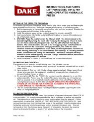
Set Up Instructions<br />
8<br />
Diagram of Unit’s Components —<br />
External View<br />
1<br />
2<br />
3<br />
4<br />
5<br />
6<br />
7<br />
9<br />
1. High Side Hose Port<br />
2. Low Side Hose Port<br />
3. Liquid Port<br />
4. Vapor Port<br />
5. Air Purge Port<br />
6. Scale Platform<br />
7. 50 lb. (23 Kg.) Unit Tank<br />
8. Oil Injector<br />
9. Tank Strap<br />
INST0462<br />
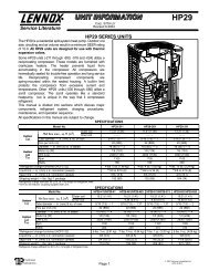
Diagram of Unit’s Components —<br />
Internal View<br />
9<br />
8<br />
1. Relays<br />
2. Compressor<br />
3. Vacuum Pump<br />
4. Filter<br />
5. Manifold Block<br />
6. Air Purge Assembly<br />
7. Low Side Hose<br />
8. High Side Hose<br />
9. Hose Holders<br />
10. Quick-Couplers<br />
(34700/34701 Only)<br />
1<br />
2<br />
3<br />
6<br />
5<br />
4<br />
7<br />
10<br />
INST0463<br />
Series 17700A/17701A/34700/34701/34704 Enviro-Charge Units<br />
3
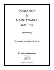
Set Up Instructions<br />
Low Side<br />
Gauge<br />
High Side<br />
Gauge<br />
Main Power Switch<br />
INST0464<br />
Low Side Valve<br />
Keypad<br />
High Side<br />
Valve<br />
SELECTING A<br />
MEASUREMENT UNIT<br />
The first step in setting up your unit is to select the unit of measure (either pounds<br />
or kilograms) to be used when operating the unit.<br />
1. Plug in the unit to the appropriate power outlet and turn ON. Press SHIFT/<br />
RESET and ENTER at the same time. The display will be blank.<br />
2. Press 0. The display will indicate the current unit of measure.<br />
3. Pressing ENTER will alternate between "LBS" and "KG". When the desired<br />
unit appears, press SHIFT/RESET.<br />
4<br />
© 1998 Robinair, SPX Corporation
PREPARING THE VACUUM PUMP<br />
Set Up Instructions<br />
The VacuMaster ® vacuum pump is shipped without oil in the reservoir. Before<br />
starting the unit, you must fill the pump with oil. Two 16-ounce (472 milliliter)<br />
bottles of oil are included with your unit.<br />
Diagram of Vacuum Pump Components<br />
1<br />
6<br />
2<br />
3<br />
4<br />
1. Oil Filler Tube<br />
2. Pump Exhaust<br />
3. Oil Fill Port<br />
4. Sight Glass<br />
5. Oil Drain Fitting<br />
6. Inlet<br />
5<br />
INST0006<br />
1. Remove the access door from the front of the unit.<br />
2. Remove the black plastic plug on the oil fill port.<br />
IMPORTANT!<br />
For maximum<br />
performance, be<br />
sure to change<br />
the vacuum<br />
pump oil<br />
frequently.<br />
3. Attach the flexible hose and cap to the oil bottle to make it easier to fill the<br />
pump.<br />
4. Pour approximately 13 ounces (384 milliliters) of vacuum pump oil into the oil<br />
fill port until oil just appears in the bottom of the sight glass on the reservoir.<br />
5. Close both manifold valves on the control panel.<br />
CAUTION! Avoid the use of an extension cord because the extension<br />
cord may overheat. However, if you must use an extension cord, use a No.<br />
14 AWG minimum and keep the cord as short as possible.<br />
6. Plug the unit into the proper voltage outlet, and turn on the unit’s MAIN<br />
POWER switch.<br />
7. Press SHIFT/RESET and ENTER at the same time to access the manual<br />
diagnostic mode.<br />
8. Press 1 to start the pump.<br />
Series 17700A/17701A/34700/34701/34704 Enviro-Charge Units<br />
5
Set Up Instructions<br />
9. While the pump is running, add enough vacuum pump oil so that the oil level is<br />
even with the line on the reservoir’s sight glass.<br />
10. Press 1 or SHIFT/RESET to stop the pump.<br />
IMPORTANT!<br />
Be sure the<br />
pump is running<br />
when<br />
adding oil.<br />
11. Replace the black plastic plug on the oil fill port.<br />
12. Replace the access door on the front of the unit.<br />
See "Maintenance Instructions" for step-by-step procedures for changing the<br />
vacuum pump oil.<br />
INSTALLING THE TANK AND<br />
PULLING A VACUUM<br />
WARNING<br />
Always wear safety goggles when working with refrigerant. Use only<br />
authorized refillable refrigerant tanks. Read and follow all warnings at the<br />
beginning of this manual before operating the unit.<br />
CAUTION! R-134a systems have special fittings (per SAE specifications)<br />
to avoid cross-contamination with R-12 systems. Do not attempt to adapt<br />
your unit for another refrigerant — system failure will result!<br />
1. A new tank comes with a dry nitrogen charge of 10 to 15 psi to keep it clean<br />
and dry during shipment. Purge its nitrogen charge by opening either valve on<br />
the tank. Vent the pressure to the atmosphere, then close the valve.<br />
2. Place the unit tank on the scale platform on the back of the unit. Securely<br />
tighten the thumbscrew on the platform to hold the tank in place. Attach the<br />
clip of the tank strap to the tank handle.<br />
3. Connect the Quick Seal TM end of the yellow hose to the air purge port on the<br />
tank. Connect the open end of the yellow hose to the port on the unit marked<br />
YELLOW.<br />
4. 34700/3470134704 Series — Attach the 16301 adapter (located on the oil<br />
drain) to the vapor valve of the tank. Attach the blue low side hose to the<br />
adapter. Open the coupler on the low side hose.<br />
17700A/17701A Series — Attach the blue low side hose to the vapor valve of<br />
the tank.<br />
5. Connect the open end of the 36” (91 cm) red vapor hose to the RED port on<br />
the back of the unit.<br />
6<br />
© 1998 Robinair, SPX Corporation
Set Up Instructions<br />
6. Connect the Quick Seal TM end of the 36” (91 cm) blue liquid hose to the blue<br />
LIQUID valve on the tank. Attach the other end of the hose to the BLUE port<br />
on the back of the unit.<br />
CAUTION! Some tanks have slightly different valve configurations. Be<br />
sure to connect the RED hose to the GAS (vapor) valve and connect the BLUE<br />
hose to the LIQUID valve.<br />
Before adding refrigerant, you must pull a vacuum on both the unit and the tank for<br />
five minutes to remove any air.<br />
7. Open both valves on the tank.<br />
8. Open the low side manifold valve on the control panel.<br />
9. Press SHIFT/RESET and ENTER at the same time.<br />
10. Press 1. The vacuum pump starts and runs continuously until you press any<br />
other key.<br />
11. Run the pump for a minimum of five minutes, then press “1” to stop the pump.<br />
12. Press SHIFT/RESET again to return to the regular display mode.<br />
13. Close the vapor valve on the tank.<br />
14. Disconnect blue low side hose from the vapor port on the tank. Remove<br />
adapter and replace on the oil drain for storage. Connect the RED hose to the<br />
vapor valve on the tank.<br />
ADDING REFRIGERANT TO THE TANK<br />
INST0466<br />
SHIFT/RESET<br />
ENTER<br />
Valve Open<br />
Valve Closed<br />
Diagram of Control Panel<br />
Series 17700A/17701A/34700/34701/34704 Enviro-Charge Units<br />
7
Set Up Instructions<br />
IMPORTANT!<br />
The 96" (244 cm)<br />
red high side hose<br />
and the 96" (244<br />
cm) blue low side<br />
hose are not used<br />
when adding<br />
refrigerant to the<br />
tank.<br />
IMPORTANT!<br />
On the 17700A/<br />
17701A Series,<br />
be sure to<br />
connect the 6"<br />
(15.2 cm) yellow<br />
adapter to the<br />
source tank<br />
BEFORE step 2.<br />
WARNING<br />
R-134a systems have special fittings (per SAE specifications) to avoid crosscontamination<br />
with R-12 systems. Do not attempt to adapt your unit for<br />
another refrigerant — system failure will result! Read and follow all warnings<br />
given at the beginning of this manual.<br />
On the 34700/34701, be sure to only purchase tanks of R-134a refrigerant<br />
that use ½” (1.2 cm) Acme threads.<br />
1. Close the blue LIQUID valve on the unit tank, and disconnect the<br />
36” (91 cm) blue liquid hose from the valve.<br />
2. 17700A/17701A Series — Connect the 6" (15.2 cm) yellow adapter to the<br />
source tank. Attach the 36” (91 cm) blue LIQUID hose to the yellow adapter.<br />
34700/34701 Series — Connect the 36” (91 cm) blue LIQUID hose to the blue<br />
LIQUID valve of the source tank. Disposable tanks have only one valve and<br />
most must be turned upside down to transfer liquid (as shown in the drawing).<br />
3. Open the blue LIQUID valve on the source tank. There is only one valve on a<br />
non-refillable tank. If you are using a non-refillable tank, follow the instructions<br />
on the side of the tank to obtain a liquid supply.<br />
1<br />
4<br />
2<br />
1. 36" Blue Liquid Hose<br />
2. Refrigerant Source Tank<br />
3. 36" Yellow Air Purge Hose<br />
4. 36" Red Vapor Hose<br />
5. Unit Tank<br />
3<br />
5<br />
INST0468<br />
Diagram of Disposable Tank Connections When Adding Refrigerant<br />
8<br />
© 1998 Robinair, SPX Corporation
Set Up Instructions<br />
CAUTION! Do not use the blue low side hose! The blue LIQUID hose is<br />
the blue hose attached to the tank’s LIQUID valve.<br />
4. Open the red GAS (vapor) valve on the unit tank.<br />
5. Press SHIFT/RESET and ENTER at the same time to access the diagnostic<br />
mode.<br />
6. Press 2 to begin transferring refrigerant. The display shows the “ADD”<br />
message for about two seconds, then shows the amount of refrigerant<br />
transferred.<br />
7. Transfer stops automatically and the display shows the “CPL” message when<br />
the source tank is empty and has been pulled to 13 in. Hg. or the weight of<br />
refrigerant in the unit tank reaches 36 pounds (16 kilograms).<br />
IMPORTANT!<br />
On the 34700/<br />
34701 Series,<br />
source tanks of<br />
R-134a must<br />
have a ½"<br />
ACME thread to<br />
match the hose<br />
fitting.<br />
CHECK REFRIGERANT<br />
This process takes about 30 minutes. You can interrupt it at any time by<br />
pressing HOLD/CONT once. To resume the ADD procedure, press HOLD/<br />
CONT again.<br />
The transfer of new refrigerant is limited by weight to leave space (about 10<br />
pounds or 4.5 kilograms of refrigerant) in the unit tank for recovery purposes.<br />
8. On the 17700A/17701A Series, close the supply valve on the source tank, and<br />
carefully disconnect the 36” (91 cm) blue liquid hose from the 6” (15.2 cm)<br />
yellow adapter, if used. Then remove the 6” (15.2 cm) yellow adapter from the<br />
source tank.<br />
On the 34700/34701 Series, if you’re using a disposable tank, turn it right side<br />
up, close its valve and carefully disconnect the 36” (91 cm) blue liquid hose.<br />
9. Reconnect the 36” (91 cm) blue liquid hose from the back of the unit to the<br />
blue LIQUID valve on the unit tank, then open that tank’s blue LIQUID valve.<br />
Any non-condensible gases in the tank will be removed during the recycling<br />
sequence.<br />
The unit is ready for use.<br />
CHECK REFRIGERANT<br />
Example<br />
weight<br />
* Enter the correct weight for<br />
your application.<br />
IMPORTANT!<br />
Be sure to close<br />
both tank valves<br />
when the unit is<br />
not in use.<br />
Inspect the unit<br />
periodically for<br />
leaks. The<br />
manufacturer<br />
does not<br />
reimburse for lost<br />
refrigerant.<br />
Series 17700A/17701A/34700/34701/34704 Enviro-Charge Units<br />
9
<strong>Operating</strong> Guidelines<br />
USING THE CONTROL PANEL<br />
The control panel has various components that control specific operating functions.<br />
MAIN POWER Switch — Supplies electrical power to the control panel.<br />
Beeper — Emits an audible tone to alert you to unit operating functions. The<br />
beeper is located on the underside of the control panel below the keypad.<br />
Digital Display — Shows the time programmed for vacuum and the weight of<br />
refrigerant programmed for recharging. Detailed instructions for programming the<br />
digital display follow this section.<br />
LOW Side Manifold Gauge — Connects to an A/C system and shows the<br />
system’s low side pressure.<br />
HIGH Side Manifold Gauge — Connects to an A/C system and shows the<br />
system’s high side pressure.<br />
LOW Side Valve — Controls the low side flow from the A/C system through the<br />
unit.<br />
HIGH Side Valve — Controls the high side flow from the A/C system through<br />
the unit.<br />
1<br />
2 3 4<br />
INST0480<br />
7 6 5<br />
Diagram of Control Panel<br />
1. Main Power Switch<br />
2. Display<br />
3. Low Side Gauge<br />
4. High Side Gauge<br />
5. High Side Valve<br />
6. Low Side Valve<br />
7. Keypad<br />
10<br />
© 1998 Robinair, SPX Corporation
<strong>Operating</strong> Guidelines<br />
KEYPAD FUNCTIONS<br />
In addition to the number keys, the keypad<br />
contains special keys that accomplish specific<br />
operating functions.<br />
• RECYCLE—Activates the recycling sequence.<br />
• RECOVER—Activates the recovery sequence.<br />
• SHIFT/RESET—Activates “shifted” positions of keys on<br />
the keypad and resets the program mode.<br />
• FILTER—Automatically recovers and evacuates to 17 in.<br />
Hg from the filter and low side of the unit.<br />
• CHG—Automatically charges the A/C system with the<br />
programmed amount of refrigerant.<br />
INST0019<br />
Diagram of Keypad<br />
• HOLD/CONT—Interrupts the automatic cycle (HOLD), then<br />
resumes functions (CONT). Press once for HOLD, and again for CONT<br />
(continue).<br />
• VACUUM—Activates the vacuum and automatic recycling sequence.<br />
• ENTER—Enters programmed data into the unit’s memory.<br />
USING THE DIGITAL DISPLAY<br />
This section explains the messages shown on the digital display, which is<br />
illustrated here for your convenience.<br />
A<br />
C<br />
B<br />
D<br />
Diagram of Digital Display<br />
Series 17700A/17701A/34700/34701/34704 Enviro-Charge Units<br />
11
<strong>Operating</strong> Guidelines<br />
Segment A — Indicates in which mode the unit is operating:<br />
PROGRAM — The unit is in the programming mode, which allows you to<br />
program vacuum time and refrigerant weight or to review the<br />
existing program.<br />
HOLD — This mode is used to change a refrigerant tank or to interrupt the<br />
vacuum/charging/recovery cycles.<br />
AUTOMATIC — Indicates that the unit is running in a given cycle and will<br />
automatically stop when the cycle is complete.<br />
Segment B — Indicates that the unit is either evacuating the A/C system or<br />
recovering, recycling or recharging refrigerant or that the unit is ready to be<br />
programmed for one of these functions:<br />
VACUUM<br />
• With PROGRAM, indicates that the unit is ready to be programmed for<br />
vacuum.<br />
• With AUTOMATIC, indicates that the vacuum pump is running; the number<br />
displayed counts down in minutes and seconds, showing the amount of time<br />
remaining.<br />
• With HOLD, indicates that HOLD/CONT was pressed to interrupt the<br />
vacuum cycle.<br />
RECYCLE<br />
• With AUTOMATIC, indicates the unit is recycling refrigerant from the tank.<br />
CHARGE<br />
• With PROGRAM, indicates that the unit is ready to be programmed for the<br />
amount of refrigerant to be charged into the A/C system; on the keypad enter<br />
the charge in pounds and hundredths of a pound or kilograms, depending on<br />
the measurement mode selected.<br />
• With AUTOMATIC, indicates the unit is charging refrigerant into the A/C<br />
system; the number shown on the digital display counts down, showing the<br />
remaining amount of refrigerant to be dispensed.<br />
• With HOLD, indicates that HOLD/CONT was pressed to interrupt the<br />
charging cycle; the number shown on the digital display is the amount of<br />
refrigerant remaining to be charged into the A/C system; to continue charging,<br />
press HOLD/CONT again.<br />
12<br />
© 1998 Robinair, SPX Corporation
<strong>Operating</strong> Guidelines<br />
RECOVER<br />
• With AUTOMATIC, indicates the unit is recovering refrigerant from the A/C<br />
system and shows the amount of refrigerant recovered in pounds or kilograms,<br />
depending on the measurement mode selected.<br />
OIL (OUNCES) or OIL (GRAMS)<br />
• Lights up as a reminder to drain the oil separator after each job.<br />
Use this chart as a quick reference for interpreting Segment B messages.<br />
VACUUM + PROGRAM = Program unit for<br />
vacuum<br />
VACUUM + AUTOMATIC = Vacuum pump is<br />
running<br />
VACUUM + HOLD = Interrupted vacuum<br />
cycle<br />
RECYCLE + AUTOMATIC = Unit is recycling<br />
refrigerant<br />
CHARGE + PROGRAM = Program unit for<br />
charge<br />
CHARGE + AUTOMATIC = Unit is charging A/C<br />
system<br />
CHARGE + HOLD = Interrupted charging<br />
cycle<br />
RECOVER + AUTOMATIC = Unit is recovering<br />
refrigerant<br />
Quick Reference Chart for Segment B<br />
Segment C — Shows a number or a coded error message on the digital display that<br />
indicates the unit’s operating status or any specific problems. See<br />
TROUBLESHOOTING TIPS for a list of error codes and messages and their<br />
descriptions.<br />
Segment D — Indicates that refrigerant is low — approximately six pounds (or 2.7<br />
kilograms) of refrigerant is left in the tank. Either replace the tank or add refrigerant<br />
following the instructions in ADDING REFRIGERANT TO THE TANK.<br />
Series 17700A/17701A/34700/34701/34704 Enviro-Charge Units<br />
13
Overview<br />
This overview is designed as a quick reference when using your Enviro-Charge<br />
unit. Read and follow all warnings in the manual.<br />
RECOVERY<br />
1. Connect hoses to vehicle: red to high side port, blue to low side port.<br />
17700A/17701A Series — Connect the red and yellow adapters to the vehicle<br />
ports first, then connect hoses.<br />
34700/34701 Series — Open the quick coupler valves after they are<br />
connected.<br />
2. Check the manifold gauges. There must be pressure to recover refrigerant.<br />
3. Open both manifold valves.<br />
4. Open both tank valves.<br />
5. Plug in the electric cord, then turn on the MAIN POWER switch.<br />
6. Press RECOVER.<br />
• Unit will clear itself of refrigerant and automatically start<br />
recovery.<br />
• Unit is in RECOVER mode of the AUTOMATIC cycle. The weight<br />
of refrigerant is displayed as it is recovered.<br />
• Unit automatically shuts off and recovery is complete.<br />
• Unit displays approximate amount recovered.<br />
7. Wait five (5) minutes; watch the gauges. If there is no rise in pressure,<br />
recovery is complete. If a rise in pressure occurs, press HOLD/CONT and<br />
repeat until pressure holds for two (2) minutes.<br />
8. Drain the oil separator and measure and record the amount of oil drained - it<br />
must be replaced with new oil during charging.<br />
14<br />
© 1998 Robinair, SPX Corporation
Overview<br />
EVACUATION<br />
1. Both manifold valves and both tank valves should still be open.<br />
2. Press SHIFT/RESET until the message "PROGRAM VACUUM MINUTES"<br />
appears on the display.<br />
3. Press VACUUM - The display counts down the vacuum time. Recycling<br />
begins automatically while the system is evacuated.<br />
4. The unit displays CPL when evacuation is complete.<br />
5. Add oil to the A/C system using the oil injector.<br />
6. Press SHIFT/RESET to move to the recharging function.<br />
RECHARGING<br />
Follow the manufacturer’s recommendation for charging.<br />
1. Be sure the appropriate manifold valves are open.<br />
2. Be sure both tank valves are open.<br />
3. Enter the refrigerant charge by weight in hundredths of a pound/kilogram.<br />
4. Press ENTER.<br />
5. Press CHG.<br />
6. The display counts down to 0, then shows CPL when complete.<br />
7. Close both manifold valves and start the vehicle. Set the vehicle’s A/C system<br />
for maximum cooling. Check the gauges and the temperature in the vehicle.<br />
8. Turn off the engine.<br />
9. Disconnect the high side hose (close the 34700/34701/34704 coupler valves<br />
first) and start the vehicle. Open both manifold valves to pull refrigerant from<br />
the hoses.<br />
10. At the lowest recommended operating pressure, close the low side valve and<br />
turn off the vehicle. On the 34700/34701/34704, close the low side valve and<br />
disconnect the low side hose. On the 17700A/17701A, disconnect the low<br />
side hose and remove the adapters.<br />
11. Close both manifold valves and turn off the MAIN POWER switch.<br />
Series 17700A/17701A/34700/34701/34704 Enviro-Charge Units<br />
15
<strong>Operating</strong> Instructions<br />
OPERATING TIPS<br />
Follow the SAE-J1991 recommended service procedure for the containment of R-<br />
12 and the SAE-J2210 recommended service procedure for the containment of R-<br />
134a.<br />
The recovery compressor is not a vacuum pump. The compressor pulls the A/C<br />
system to a partial vacuum only. You must use the unit’s vacuum cycle to remove<br />
moisture from the A/C system. We recommend a minimum 15-minute vacuum with<br />
more time as required by the system manufacturer.<br />
This unit is designed to be used with the manifold gauge set built into the control<br />
panel.<br />
It includes a 6 cfm (142 l/m) VacuMaster ® high vacuum pump for fast, thorough<br />
evacuation. Be sure to change the vacuum pump oil when the “OIL” message<br />
appears on the display.<br />
R-134a systems require special oils in place of the mineral oil used with R-12<br />
systems. Refer to the A/C system manufacturer’s service manuals for oil<br />
specifications.<br />
16<br />
© 1998 Robinair, SPX Corporation
<strong>Operating</strong> Instructions<br />
RECOVERING REFRIGERANT<br />
WARNING<br />
Some R-12 automotive fuel systems use a ¼” male SAE flare access fitting.<br />
Connecting your air conditioning service or recovery/recycling equipment to<br />
this fitting can result in cross-contamination of either the fuel system or the<br />
air conditioning service equipment. These conditions can be potentially<br />
dangerous due to the flammable characteristics of gasoline. Always refer to<br />
your vehicle manual prior to connection.<br />
CAUTION! R-134a systems have special fittings (per SAE specifications)<br />
to avoid cross-contamination with R-12 systems. Do not attempt to adapt<br />
your unit for another refrigerant — system failure will result! Read and follow<br />
all warnings at the beginning of this manual before operating the unit.<br />
Before beginning recovery, be sure your unit is set up as shown. Also be sure there<br />
is refrigerant in the tank and vacuum pump oil in the vacuum pump. See "Set Up<br />
Instructions."<br />
1<br />
Diagram of Hose Connections<br />
2<br />
3<br />
4<br />
5<br />
1. Oil Injector<br />
2. Quick-Couplers<br />
(34700/34701 Series)<br />
3. Blue Liquid Hose<br />
4. Red Vapor Hose<br />
5. Yellow Air Purge Hose<br />
Note:<br />
High and low side hoses on the<br />
34700/34701 Series with Quick-<br />
Couplers are shown. The 17700A/<br />
17701A Series have SAE fittings.<br />
INST0470<br />
Series 17700A/17701A/34700/34701/34704 Enviro-Charge Units<br />
17
<strong>Operating</strong> Instructions<br />
IMPORTANT!<br />
Run the A/C<br />
system for a few<br />
minutes before<br />
starting the<br />
recovery process.<br />
Tests show more<br />
refrigerant is<br />
recovered if this<br />
action is taken.<br />
Turn the system<br />
off before<br />
proceeding.<br />
1. Connect the hoses to the vehicle as follows:<br />
17700A/17701A Series —<br />
• Attach the proper adapters to the low side and high side fittings on the vehicle.<br />
(An adapter package comes with each unit.)<br />
• Connect the unit’s 96” (244 cm) red high side hose to the adapter attached to<br />
the vehicle’s high side fitting.<br />
• Connect the unit’s 96” (244 cm) blue low side hose to the adapter attached to<br />
the vehicle’s low side fitting.<br />
34700/34701/34704 Series —<br />
• Connect the unit’s 96” (244 cm) red high side hose with the Quick-Coupler to<br />
the high side fitting of the A/C system, then open the<br />
coupler valve.<br />
• Connect the unit’s 96” (244 cm) blue low side hose with the Quick-Coupler to<br />
the low side fitting of the A/C system, then open the coupler valve.<br />
2. Check the manifold gauges on the unit’s control panel — they should both<br />
register above zero. If there is no system pressure, there is no refrigerant in the<br />
system to recover or the hoses are not connected properly.<br />
3. Be sure the oil drain valve is closed.<br />
4. Open both manifold valves on the control panel.<br />
Manifold Gauges<br />
INST0471<br />
Diagram of Control Panel<br />
Valves Open<br />
18<br />
© 1998 Robinair, SPX Corporation
<strong>Operating</strong> Instructions<br />
INST0472<br />
Diagram of Control Panel<br />
RECOVER<br />
5. Open the GAS (vapor) valve and the LIQUID valve on the tank.<br />
6. Connect the power cord to the back of the unit and plug the cord into the<br />
proper voltage outlet. Turn on the MAIN POWER switch.<br />
7. Press RECOVER.<br />
Before recovery begins, the unit clears itself of any refrigerant remaining in the<br />
various components. You’ll know this is occurring because the compressor will<br />
start and the “CL-L” message will display. This process takes up to 4 minutes to<br />
complete. Once the clearing is complete, the unit automatically begins to recover<br />
refrigerant from the system.<br />
CAUTION! If the A/C system pressure is 25 psi or less, the message<br />
“CH-P” appears on the display to alert you not to attempt recovery from an<br />
empty system. Do not press HOLD/CONT to continue the recovery process<br />
unless you know the A/C system contains refrigerant.<br />
The display shows that the unit is in the RECOVER mode and the AUTOMATIC<br />
cycle. You can monitor the amount of refrigerant removed from the system by<br />
watching the display. The compressor shuts off automatically when recovery is<br />
complete (at approximately 13 in. Hg). The display shows the “CPL” message and<br />
then alternately flashes the weight of refrigerant recovered and the “OIL<br />
(OUNCES)/OIL (GRAMS)” message.<br />
8. To assure complete recovery of refrigerant, wait for 5 minutes and watch the<br />
manifold gauges for a rise in pressure above “0.” If a rise occurs, press HOLD/<br />
CONT. Repeat as needed until the system pressure holds for 2 minutes.<br />
CHECK REFRIGERANT<br />
Series 17700A/17701A/34700/34701/34704 Enviro-Charge Units<br />
19
<strong>Operating</strong> Instructions<br />
CAUTION! Drain the oil separator after each recovery. The display will<br />
indicate “OIL (OUNCES)” or “OIL (GRAMS)” as a reminder.<br />
9. Be sure the oil catch bottle is empty, then slowly open the oil drain valve, and<br />
drain the oil into the oil catch bottle. This oil was removed from the A/C<br />
system during recovery. When all the recovered oil has completely drained,<br />
close the valve and record the amount of oil in the bottle.<br />
Diagram of Oil Drain Valve<br />
and Bottle<br />
1. Oil Drain Valve<br />
2. Oil Catch Bottle<br />
1<br />
INST0473<br />
2<br />
If the recovery tank fills completely:<br />
• The compressor shuts off and the digital display shows the message<br />
“FULL.”<br />
• Change the tank.<br />
The A/C system is now empty. Make any repairs at this time.<br />
20<br />
© 1998 Robinair, SPX Corporation
<strong>Operating</strong> Instructions<br />
EVACUATING THE A/C SYSTEM<br />
WARNING<br />
Always wear safety goggles when working with refrigerant. Use only<br />
authorized refillable refrigerant tanks. Read and follow all warnings at the<br />
beginning of this manual before operating the unit.<br />
This station is UL-certified as a single-pass unit. During evacuation,<br />
refrigerant is automatically recycled to assure recharging with the cleanest possible<br />
refrigerant in no additional time.<br />
1. With the 96” (244 cm) high side and low side hoses connected to the A/C<br />
system, open both manifold valves on the control panel.<br />
2. Open both the GAS (vapor) valve and the LIQUID valve on the tank.<br />
3. To program the length of evacuation time, press SHIFT/RESET until the<br />
display shows that the unit is in the VACUUM mode.<br />
4. For your convenience, a default vacuum time is preprogrammed to appear on<br />
the digital display at start-up. If the default time is correct, proceed to Step 5.<br />
You can override this default setting by entering a different length of time in<br />
both minutes and seconds. Enter the required time by pressing the appropriate<br />
number keys, then press ENTER. The display shows the time in minutes.<br />
5. Press VACUUM to start the vacuum pump. If the message "U-HI" appears,<br />
you have 25 psi or greater of pressure at the inlet. You must recover that<br />
pressure to continue. If necessary, press RECOVER.<br />
The digital display counts down the remaining evacuation time in minutes and<br />
seconds. Recycling begins automatically five (5) seconds after the vacuum pump<br />
starts, and the “RECYCLE” message illuminates to indicate the unit is recycling<br />
refrigerant. Non-condensible gases (mostly air) are automatically vented from the<br />
tank during the recycling process, sometimes producing an audible pressure release<br />
(a hissing sound). This is a normal function.<br />
6. The vacuum sequence continues for the programmed length of time, then<br />
displays the “CPL” message to indicate that evacuation is complete.<br />
7. Pressing SHIFT/RESET at this point moves you to the charging process.<br />
IMPORTANT!<br />
You should<br />
evacuate for at<br />
least 15 minutes<br />
for adequate<br />
moisture and<br />
contaminant<br />
removal.<br />
IMPORTANT!<br />
If the vacuum pump<br />
has run for 10 or<br />
more hours without<br />
an oil change, the<br />
message “OIL”<br />
flashes on the display.<br />
Change the pump oil<br />
following the<br />
procedures in the<br />
MAINTENANCE<br />
INSTRUCTIONS.<br />
Series 17700A/17701A/34700/34701/34704 Enviro-Charge Units<br />
21
<strong>Operating</strong> Instructions<br />
Option A<br />
You can recycle refrigerant only (without pulling a vacuum) for an indefinite<br />
period of time by pressing SHIFT/RESET and RECYCLE at the same time.<br />
To cancel this operation, again press SHIFT/RESET.<br />
Option B<br />
If you require vacuum only, press SHIFT/RESET and ENTER at the same<br />
time, then press 1. Run the vacuum pump as long as required, then press 1 or<br />
SHIFT/RESET to cancel.<br />
Option C<br />
You can automatically charge refrigerant after the vacuum cycle:<br />
1. Press SHIFT/RESET and ENTER at the same time. The display will be<br />
blank.<br />
2. Press 4, the display will show "AUTOMATIC", "VACUUM" and either "00"<br />
or "11." "00" indicates a disabled auto-charge and "11" indicates an enabled<br />
auto-charge.<br />
3. Press ENTER to shift between enabled and disabled auto-charge. Press<br />
SHIFT/RESET to lock in mode choice to memory.<br />
INST0483<br />
Diagram of Control Panel<br />
SHIFT/RESET ENTER VACUUM<br />
22<br />
© 1998 Robinair, SPX Corporation
<strong>Operating</strong> Instructions<br />
REPLENISHING A/C SYSTEM OIL<br />
Before charging the A/C system, you must replenish any oil removed from the A/C<br />
system during the recovery process.<br />
1. Select the correct oil for the A/C system being serviced. Refer to the system<br />
manufacturer’s service manual.<br />
CAUTION! To prevent air from entering the A/C system, never let the<br />
oil level drop below the pick up tube while charging or replenishing.<br />
2. Adjust the O-ring around the oil bottle to the required oil charge level. For<br />
example, if the bottle’s oil level is at 4 ounces and you need only ½ an ounce<br />
of oil to replenish the A/C system, place the O-ring at the 3½ ounce level.<br />
3. Install the bottle on the oil injection system on the back of the unit.<br />
CAUTION! Never open the oil injection valve while there is positive<br />
pressure in the A/C system. This could blow oil back through the bottle vent.<br />
4. Open the high side manifold valve.<br />
5. Press the oil injection valve at the top of the bottle, and watch the level of oil<br />
being drawn into the A/C system.<br />
6. Release the valve when the required oil charge has been pulled into the system.<br />
1<br />
2<br />
Diagram of Oil Injection<br />
System<br />
1. Oil Injector Valve<br />
2. Oil Injection Bottle<br />
INST0475<br />
Series 17700A/17701A/34700/34701/34704 Enviro-Charge Units<br />
23
<strong>Operating</strong> Instructions<br />
IMPORTANT!<br />
You can charge<br />
oil through either<br />
the low side or<br />
high side, or<br />
both, depending<br />
on the vehicle<br />
manufacturer’s<br />
recommendation.<br />
Just open the<br />
appropriate<br />
manifold valve or<br />
valves.<br />
IMPORTANT!<br />
Do not place any<br />
weight (including<br />
your hands and<br />
feet) on the tank<br />
or scale during<br />
the refrigerant<br />
transfer process.<br />
Any weight<br />
disturbance will<br />
cause an<br />
incorrect transfer.<br />
RECHARGING THE A/C SYSTEM<br />
WARNING<br />
Always wear safety goggles when working with refrigerant. Use only<br />
authorized refillable refrigerant tanks. Disconnect hoses with extreme<br />
caution!<br />
All hoses may contain liquid refrigerant under pressure. Read and follow all<br />
warnings at the beginning of this manual before operating the unit.<br />
CAUTION! To be sure the unit tank has sufficient refrigerant for<br />
recharging, press SHIFT/RESET once to access the program mode, then press<br />
SHIFT/RESET and ENTER at the same time to enter the diagnostic mode. Then<br />
press “6.” The display must show 36 pounds (16 kilograms) or more because<br />
the empty weight of the tank is 28 pounds (13 kilograms) and about 8<br />
pounds (four kilograms) of refrigerant is required to assure a complete A/C<br />
system charge. If the amount displayed is less than 36 pounds (16<br />
kilograms), add new refrigerant to the tank following the instructions in<br />
ADDING REFRIGERANT TO THE TANK.<br />
When you turn on the unit, you can enter the amount of refrigerant to be charged.<br />
The unit stores this value in memory until you turn it off or program a different<br />
amount.<br />
1. Open the appropriate manifold valve(s) on the control panel.<br />
2. Be sure both valves on the tank are open.<br />
3. Enter the amount of refrigerant required to recharge the system by pressing the<br />
appropriate number keys. The charge must be entered in hundredths of a<br />
pound or kilogram — the same way the nameplate on the vehicle’s A/C system<br />
specifies the charge.<br />
4. Press ENTER.<br />
5. Press CHG to begin the charging process. The digital display shows the<br />
“AUTOMATIC” message and the weight of refrigerant you’ve programmed<br />
for recharge. The charging solenoid opens to transfer refrigerant, the display<br />
counts down to zero, and the “CPL” message displays when charging is<br />
complete.<br />
6. Close the manifold valve(s).<br />
24<br />
© 1998 Robinair, SPX Corporation
<strong>Operating</strong> Instructions<br />
CAUTION! Be sure both manifold valves are closed before starting the<br />
A/C system.<br />
WARNING<br />
Before starting the vehicle's engine, check to see that it is in PARK or<br />
NEUTRAL with the emergency brake on. Never run a vehicle without<br />
adequate ventilation.<br />
7. Start the vehicle’s A/C system, and let it run until the gauge pressure readings<br />
stabilize (compare the gauge readings with the system manufacturer’s<br />
specifications).<br />
8. Check the evaporator outlet temperature to be sure that the A/C system is<br />
operating properly (refer to the system manufacturer’s specifications for the<br />
proper temperature).<br />
9. Turn off the vehicle’s engine.<br />
On the 17700A/17701A Series:<br />
10. Disconnect the 96” (244 cm) red high side hose from the high side adapter.<br />
11. Disconnect the 96” (244 cm) blue low side hose from the low side adapter.<br />
12. Remove the adapters from the vehicle’s A/C system by pushing down on the<br />
coupler while unscrewing the fitting.<br />
On the 34700/34701/34704 Series:<br />
10. Close the high side coupler valve, then disconnect the 96” (244 cm) red high<br />
side hose from the A/C system.<br />
11. Restart the vehicle, then open both manifold valves on the control panel.<br />
Refrigerant from both hoses will be drawn quickly into the A/C system<br />
through the blue low side hose.<br />
12. When both gauges show the lowest operating pressure recommended by the<br />
manufacturer, close the low side valve and turn off the vehicle’s engine.<br />
On Both Series:<br />
13. Close the low side coupler valve and disconnect the 96” (244 cm) blue low<br />
side hose from the A/C system.<br />
CHECK REFRIGERANT<br />
IMPORTANT!<br />
If the message<br />
“ADD” appears,<br />
there is not<br />
sufficient<br />
refrigerant in the<br />
tank. Follow the<br />
instructions in<br />
ADDING<br />
REFRIGERANT TO<br />
THE TANK.<br />
IMPORTANT!<br />
For maximum<br />
charging<br />
accuracy, you<br />
must clear the<br />
hoses of all<br />
refrigerant.<br />
14. Close both manifold valves, and turn off the MAIN POWER switch.<br />
Series 17700A/17701A/34700/34701/34704 Enviro-Charge Units<br />
25
<strong>Operating</strong> Instructions<br />
CORRECTING AN INCOMPLETE CHARGE<br />
On rare occasions, you may find that the total charge does not transfer to the A/C<br />
system. There are two reasons why this can occur:<br />
1. The refrigerant transfer is too slow because the pressure in the unit tank and in<br />
the A/C system is equal. When this happens, the unit emits an audible signal<br />
and the display shows the weight of refrigerant remaining to be transferred. To<br />
pull the remainder of the charge into the A/C system, you should:<br />
• Close the high side valve on the control panel.<br />
• Open the low side valve on the control panel.<br />
• Start the A/C system and press HOLD/CONT. The remaining charge is pulled<br />
into the system and the display shows the “CPL” message.<br />
2. The transfer will not complete and the display shows the “CHECK<br />
REFRIGERANT” message because there is not enough refrigerant in the tank<br />
to complete the process. You must then recover the partial refrigerant charge<br />
in the A/C system, add refrigerant to the tank and complete another evacuation<br />
and charge procedure:<br />
• Press HOLD/CONT to interrupt the cycle.<br />
• Press SHIFT/RESET to reset the unit.<br />
• Recover the refrigerant that was charged into the A/C system, following the<br />
instructions in RECOVERING REFRIGERANT.<br />
• Add refrigerant to the tank, following the instructions in ADDING<br />
REFRIGERANT TO THE TANK.<br />
• Evacuate the A/C system, following the instructions in EVACUATING THE<br />
A/C SYSTEM.<br />
• Recharge the A/C system.<br />
The vehicle now has a complete charge.<br />
HOLD/CONT<br />
26<br />
INST0477<br />
Diagram of Charging Connections<br />
SHIFT/RESET<br />
© 1998 Robinair, SPX Corporation
Maintenance Instructions<br />
There are just a few routine maintenance procedures necessary to keep your unit<br />
operating properly.<br />
CHECKING THE SCALE ACCURACY<br />
To ensure continued charging accuracy, check your scale using these procedures<br />
every thirty (30) days or 100 service jobs, whichever comes first.<br />
Also if the microprocessor senses that calibration has been lost, the "CAL" message<br />
displays. Follow this procedure to check the scale accuracy:<br />
1. While in the PROGRAM mode, press SHIFT/RESET and ENTER at the<br />
same time to enter the diagnostic mode and clear the digital display.<br />
2. Press 6 to display the approximate scale platform weight.<br />
3. Remove the tank from the scale platform. The empty platform weight<br />
displayed should be zero. (± 2 pounds or ±1 kilogram)<br />
• If the displayed weight is not within these limits, the CHECK<br />
REFRIGERANT message will also display. Call the manufacturer.<br />
• If the display does not show the correct weight with ±.1 lb., see "Calibrating<br />
the Scale " section.<br />
4. If the calibration is correct, press SHIFT/RESET to exit.<br />
SHIFT/RESET<br />
ENTER<br />
INST0474<br />
Diagram of Control Panel<br />
Series 17700A/17701A/34700/34701/34704 Enviro-Charge Units<br />
27
Maintenance Instructions<br />
CALIBRATING THE SCALE<br />
IMPORTANT!<br />
You must have a known exact weight of 40 lbs. ± .01 (18.14 kg ± .005)<br />
1. Remove all weight from the scale platform.<br />
2. Turn on the MAIN POWER switch.<br />
3. Press SHIFT/RESET and ENTER at the same time.<br />
4. Press 8-7-8-7. The display will show "A-1."<br />
NOTE: If you press any other key before the 8-7-8-7 sequence, you will not be<br />
able to enter the automatic calibration routine.<br />
5. Press 0 and then ENTER. The display will show "0.00" and then change to<br />
the A-2" message.<br />
6. Place a known exact weight of 10-60 lbs. on the center of the platform. Enter<br />
that weight on the display using the keypad, then press ENTER. The display<br />
will return to the vacuum mode.<br />
7. Check the scale accuracy by pressing SHIFT/RESET and ENTER and the<br />
same time. When the diagnostics mode is entered (the display is blank) press<br />
6. The display shows the amount of weight on the scale platform, and 0.00<br />
when it is removed.<br />
28<br />
© 1998 Robinair, SPX Corporation
Maintenance Instructions<br />
CALIBRATING UL CIRCUIT<br />
WARNING<br />
Unlplug the unit before beginning any service work. Improper use or<br />
connections can cause electrical shock. Only qualified personnel should<br />
perform service work.<br />
If the scale assembly and UL circuit are not calibrated, the scale can overfill<br />
the tank, causing possible explosion and/or vehicle overcharge.<br />
Live AC voltages are present in the unit when the power is turned on. use<br />
caution when making the adjustments below.<br />
The scale on the 700 series units will only handle a 50lb. tank. The UL circuit is a<br />
tank overfill protection device. The main board is programmed to display FULL at<br />
73 lbs. (33.11 kg.) the UL circuit is set as a back up fail safe to the programming.<br />
Follow these steps to calibrate the circuit:<br />
1. Remove all weight from the scale platform. Remove the shroud from the unit<br />
by removing (3) screws. Also, be sure to remove the oil bottle by loosening (2)<br />
screws.<br />
2. Turn on the MAIN POWER switch.<br />
NOTE: Press 0 to enter the pound or kilogram selection mode. Press ENTER to<br />
toggle between lb. or kg. Press SHIFT/RESET and ENTER to accept the<br />
displayed setting and exit mode.<br />
3. Press SHIFT/RESET and ENTER at the same time.<br />
4. Press 6 to display the absolute weight on the scale.<br />
5. Place exactly 76 lbs. ± .01 lbs. (34.5kg. ± .005 kg.) on the scale and, with a<br />
small screwdriver, adjust the P1-POT* (Potentiometer) until the display just<br />
indicates HOLD.<br />
6. Remove one pound from the scale and the HOLD segment should go off.<br />
Press SHIFT/RESET to return to normal operations.<br />
Series 17700A/17701A/34700/34701/34704 Enviro-Charge Units<br />
29
Maintenance Instructions<br />
UL CIRUIT CALIBRATION (continued)<br />
NOTE: Certified weights can be added to check positive response and then<br />
removed to check negative response.<br />
7. Reassemble oil bottle and shoud back on the unit.<br />
8. While the circuit calibration is now finished, the scale must still be calibrated<br />
to complete the calibrating procedure.<br />
* The P-1 POT (Potentiometer) is located below the keypad at the front of the<br />
circuit board.<br />
NOTE: This entire procedure must be completed to update the scale calibration<br />
memory of the unit. turning off the power at any time dureing the procedure returns<br />
the unit to the previous calibration values and the procedure must be started again<br />
from the beginning.<br />
30<br />
© 1998 Robinair, SPX Corporation
REPLACING THE FILTER-DRIER<br />
The filter-drier on this unit is designed to trap acid and<br />
particulates and is formulated to remove water from the<br />
refrigerant. You must change the filter-drier to assure<br />
adequate moisture and contaminant removal.<br />
Typically, you can recycle up to 300 pounds (136<br />
kilograms) of R-134a or 600 pounds (272 kilograms) of<br />
R-12 between filter changes. To help you know when<br />
you’ve reached that point, the unit displays the “CH-F”<br />
warning message, prompting you to change the filterdrier.<br />
Once the “CH-F” message displays, you can:<br />
• Bypass the filter replacement routine:<br />
Press HOLD/CONT, and resume operation to<br />
complete a procedure before changing the filterdrier.<br />
Maintenance Instructions<br />
CAUTION! For best results, use Robinair filterdriers<br />
(part no. 34724). All performance tests and<br />
claims are based on using this specially-blended<br />
filter-drier. Use of another may affect performance<br />
results.<br />
INST0477<br />
Diagram of<br />
Filter-Drier<br />
• Start the filter changeout routine:<br />
1. If they are open, close both manifold valves.<br />
2. Open the oil drain valve and make certain all oil has been drained, then close<br />
the valve. Remove oil drain bottle and dispose of used oil in accordance with<br />
all local and state regulations.<br />
3. Connect the blue low side hose to the oil drain port. Open the oil drain valve.<br />
On 34700/34700 Series, open the valve located at the end of the low side hose.<br />
4. Open the low side valve on the control panel.<br />
5. Press SHIFT/RESET and FILTER at the same time to recover all the<br />
remaining refrigerant from the low side of the unit. The display shows the<br />
messages “FIL,” “AUTOMATIC” and “RECOVER.” When all of the<br />
refrigerant has been removed, the messages change to “FIL” and “HOLD” to<br />
indicate the unit is waiting for the filter replacement.<br />
Series 17700A/17701A/34700/34701/34704 Enviro-Charge Units<br />
31
Maintenance Instructions<br />
Filter-<br />
Drier<br />
6. When all of the refrigerant has been recovered,<br />
remove the filter-drier by unscrewing it from the<br />
manifold block. Dispose of the used filter-drier<br />
properly.<br />
7. Remove the cap from the filter-drier, then install<br />
the new filter-drier. Tighten to 120 in. lbs.<br />
INST0479<br />
8. Press HOLD/CONT. The vacuum pump starts<br />
automatically and runs for five minutes before<br />
shutting off. The messages on the digital display<br />
change to “FIL” and “VACUUM.”<br />
9. After the vacuum pump shuts off, close the oil<br />
drain valve. Remove the low side hose from the<br />
oil drain port and reinstall the oil drain bottle.<br />
NOTE: 34700/34701/34704 Series<br />
units use special fittings at the ends of<br />
the charging hoses. 17700A/17701A<br />
Series units use standard ¼" SAE flare<br />
fittings.<br />
1<br />
2<br />
3<br />
Diagram of Oil Injection System<br />
1. Oil Drain Port<br />
2. Oil Drain Valve<br />
3. Low Side Hose Valve<br />
(34700/34701/34704 Series Only)<br />
32<br />
© 1998 Robinair, SPX Corporation
Maintenance Instructions<br />
CHANGING THE VACUUM PUMP OIL<br />
For maximum vacuum pump performance, change the vacuum pump oil when the<br />
"OIL" message flashes on the display (the vacuum pump has run for more than 10<br />
hours or more without an oil change).<br />
1. Turn on the MAIN POWER switch. The display shows the messages<br />
“PROGRAM - VACUUM - MINUTES - 15:00.”<br />
2. Press VACUUM. The display shows the "OIL" message.<br />
3. Press SHIFT/RESET and ENTER at the same time to reset the 10 hour<br />
timer.<br />
4. Press VACUUM again, and let the vacuum pump run for 5 minutes.<br />
NOTE: If the display indicates "OIL", press SHIFT/RESET and ENTER at the<br />
same time to reset the 10 hour timer.<br />
5. At the end of 5 minutes, press HOLD.<br />
6. Remove the access door from the front of the unit.<br />
7. Remove the black plastic plug on the oil fill port.<br />
8. Remove the oil drain cap from the vacuum pump, then drain the<br />
contaminated oil into a suitable container and dispose of it properly.<br />
9. Replace the oil drain cap.<br />
10. Attach the flexible tube and cap to the oil bottle and pour 5 ounces of vacuum<br />
pump oil into the oil fill port.<br />
11. Press CONT. While the pump is running, slowly add new vacuum pump oil<br />
until the oil level is even with the line on the reservoir’s sight glass.<br />
12. Replace the black plastic plug on the oil fill port.<br />
13. Replace the access door on the front of the unit.<br />
14. Press VACUUM to continue or turn the MAIN POWER switch to OFF.<br />
Series 17700A/17701A/34700/34701/34704 Enviro-Charge Units<br />
33
Maintenance Instructions<br />
Diagram of Vacuum Pump<br />
1. Oil Filler Tube<br />
2. Pump Exhaust<br />
3. Oil Fill Port<br />
4. Sight Glass<br />
5. Oil Drain Fitting<br />
6. Inlet<br />
1<br />
6<br />
2<br />
3<br />
4<br />
5<br />
INST0006<br />
IMPORTANT!<br />
Inspect the unit<br />
periodically for<br />
leaks. The<br />
manufacturer<br />
does not<br />
reimburse for lost<br />
refrigerant.<br />
CHECKING FOR LEAKS<br />
Every three months, or as specified by local or state laws, you should check your<br />
unit for leaks.<br />
1. Turn off the MAIN POWER switch, and disconnect the power cord from the<br />
outlet.<br />
2. Remove the shroud by removing the threaded screws at the back of the unit.<br />
3. Use a leak detector to probe all fitting connections for refrigerant leaks.<br />
Tighten fittings if a leak is indicated.<br />
4. Replace the shroud.<br />
34<br />
© 1998 Robinair, SPX Corporation
Troubleshooting Tips<br />
USING MANUAL DIAGNOSTICS<br />
WARNING<br />
Be sure to discharge any system pressure before performing any manual<br />
diagnostics.<br />
This unit’s manual diagnostics mode is easily accessible through the keypad.<br />
1. Press SHIFT/RESET and ENTER at the same time. The display should be<br />
blank except for the decimal point.<br />
2. Press the following keys to perform these functions:<br />
Press 1 — Starts the vacuum pump to begin evacuation. Press 1 again (or<br />
SHIFT/RESET) to turn off the pump.<br />
Press 2 — Begins the transfer of refrigerant. The “ADD” message displays<br />
momentarily, then the display shows the amount of refrigerant transferred.<br />
Press HOLD/CONT at any time to interrupt the transfer and again to resume<br />
operation.<br />
Press 3 — Displays the total amount of refrigerant recovered. Each time<br />
recovery is completed, that amount is added to the existing total. To clear the<br />
internal counter, press SHIFT/RESET and ENTER at the same time while<br />
the total is being displayed. The maximum amount recorded is 9,999 pounds<br />
(or 99 kilograms) of refrigerant.<br />
Press 4 — Automatic charge after the vacuum cycle. The display will show<br />
"AUTOMATIC", "VACUUM," and either "00" or "11." "00" indicates a<br />
disabled auto-charge and "11" indicates an enabled auto-charge. Press<br />
ENTER to shift between enabled and disabled auto-charge. Press SHIFT/<br />
RESET to lock in mode choice to memory.<br />
Press 5 — All display segments light up. Press 5 again to turn off.<br />
Press 6 — Displays the approximate weight on the scale.<br />
See CHECKING THE SCALE ACCURACY for diagnostic procedures.<br />
Press 7 — Displays the weight of refrigerant contained in the tank.<br />
3. Press SHIFT/RESET to return to the PROGRAM mode.<br />
Series 17700A/17701A/34700/34701/34704 Enviro-Charge Units<br />
35
Troubleshooting Tips<br />
RECOVERY OPERATION<br />
Compressor does not start or stops prematurely<br />
Problem: Power cord not plugged in or no power at plug<br />
Solution:Check circuit for power<br />
Problem: MAIN POWER switch is off<br />
Solution:Turn on switch<br />
Problem: “FULL” message on digital display<br />
Solution:Change tanks. See INSTALLING THE TANK<br />
Problem: “HI-P” message on digital display<br />
Solution:Be sure tank valves are open and hoses are properly connected<br />
to the tank, or<br />
Check the scale calibration. See CHECKING THE SCALE<br />
ACCURACY<br />
Problem: “CH-F” message on digital display<br />
Solution:Remove and replace the filter-drier. See REPLACING THE<br />
FILTER-DRIER and be sure to pull a vacuum<br />
Problem: Faulty components<br />
Solution:Call service center<br />
Runs a short time, but does not complete recovery<br />
Problem: Tank valves closed<br />
Solution:Open both valves and be sure hoses are properly connected to<br />
the tank<br />
Problem: Manifold valves closed<br />
Solution:Open both valves<br />
Problem: Faulty components<br />
Solution:Call service center<br />
Runs but won’t shut off<br />
Problem: Oil drain valve open<br />
Solution:Close the valve<br />
Problem: Leak in vehicle system<br />
Solution:Locate and repair all system leaks<br />
Problem: Hoses are not properly connected to the vehicle<br />
Solution:Check hose connections<br />
Problem: Faulty components<br />
Solution:Call service center<br />
36<br />
© 1998 Robinair, SPX Corporation
Troubleshooting Tips<br />
RECHARGING OPERATION<br />
No power when Main Power switch is on—no display showing<br />
Problem: Unit unplugged<br />
Solution:Plug the unit into a power source<br />
Problem: No power at wall outlet<br />
Solution:Locate the problem with the outlet or change outlets<br />
Audible tone sounds during refrigerant transfer<br />
Problem: Transfer stopped or too slow<br />
Solution:Start the A/C system and pull the remaining refrigerant into<br />
system. See RECHARGING THE A/C SYSTEM or<br />
Be sure the blue hose has access to the tank<br />
Problem: Refrigerant supply empty<br />
Solution:Add refrigerant to the tank<br />
Problem: Blue LIQUID tank valve closed<br />
Solution:Open the blue LIQUID tank valve<br />
Refrigerant does not flow<br />
Problem: Refrigerant supply empty<br />
Solution:Add refrigerant to the tank<br />
Problem: Flow restriction<br />
Solution:Check all connections on the A/C system (the 17700A/17701A<br />
should have adapters on both the low and high side fittings and<br />
the couplers on the 34700/34701 should be open), or<br />
Check the blue hose connection at the tank’s blue valve — be<br />
sure it is getting access, or<br />
Check the tank’s blue valve — it should be open, or<br />
Be sure the A/C system has had a minimum of 15 minutes of<br />
vacuum<br />
Vacuum pump runs, but low side gauge does not register an<br />
appropriate vacuum<br />
Problem: Pump oil contaminated<br />
Solution:Flush and change the vacuum pump oil<br />
Problem: Charging line loose<br />
Solution:Check connections<br />
Problem: Manifold leaking<br />
Solution:Check connections<br />
Problem: Low side valve closed<br />
Solution:Open low side valve<br />
Problem: 3 /8” hose improperly connected to pump<br />
Solution:Check connections<br />
Series 17700A/17701A/34700/34701/34704 Enviro-Charge Units<br />
37
Troubleshooting Tips<br />
ERROR/MESSAGE CODES<br />
ADD<br />
CAL<br />
CH-F<br />
CH-P<br />
CL-L<br />
CLR<br />
CON<br />
CPL<br />
FIL<br />
FULL<br />
HI-P<br />
OIL<br />
SCAL<br />
U-HI<br />
99LB<br />
There is less than six pounds (2.7 kilograms) of refrigerant in the<br />
tank. Add refrigerant to the tank.<br />
The scale is out of calibration. Calibrate the scale.<br />
The unit has recovered 300 pounds of refrigerant. Press SHIFT/<br />
RESET and FILTER at the same time, then replace the filterdrier.<br />
The vehicle’s A/C system has less than 25 psi. Do not attempt<br />
recovery if the A/C system has no refrigerant. Check for<br />
restrictions at access fittings. Check the manifold valve positions<br />
(they should be open). To continue, press HOLD/CONT.<br />
The low side clearing routine is in progress. This occurs when<br />
you press RECOVER and can last up to four minutes.<br />
The unit is in the self-clearing process.<br />
The vacuum pump will run continuously. Press SHIFT/RESET to<br />
stop.<br />
The specified cycle function (recovery, evacuation, charging or<br />
adding refrigerant) is complete.<br />
The filter-drier changeout is in progress.<br />
The refrigerant recovery tank is full. Replace the tank.<br />
The discharge pressure is above 435 psi. Check to be sure the<br />
unit tank’s red valve is open.<br />
The vacuum pump has run for 10 hours. While the “OIL”<br />
message is displayed, press SHIFT/RESET and ENTER at the<br />
same time to reset the timer. Then change the vacuum pump oil.<br />
The scale is damaged, disconnected, out of calibration or<br />
overloaded (it cannot exceed 80 pounds or 36.3 kilograms).<br />
Calibrate the scale.<br />
There is positive pressure on the vacuum pump. Press SHIFT/<br />
RESET and then RECOVER to remove the pressure, then<br />
continue the evacuation procedure.<br />
The maximum amount displayed during recovery is 99 pounds<br />
(or 99 kilograms). Press SHIFT/RESET to clear the display.<br />
38<br />
© 1998 Robinair, SPX Corporation
Replacement Parts List<br />
The following is a list of replacement parts and accessories you may need to service<br />
or maintain your unit.<br />
The 50-pound (23 kilograms) refillable refrigerant tank is the only tank you should<br />
use with this unit. The unit’s overfill limitation mechanism has been calibrated<br />
specifically for use with this tank, and the tank’s valving is set up specifically for use<br />
with this unit.<br />
We suggest you keep several filter-driers on hand so you will always be able to<br />
change them and complete any recycling job that is in progress.<br />
Premium High Vacuum Pump Oil is also available in handy quart containers or in<br />
convenient gallon containers:<br />
Quart (shipped 12 quarts per case) 13203<br />
Gallon (shipped 4 gallons per case) 13204<br />
Because of ongoing product<br />
improvements, we reserve the right<br />
to change design, specifications, and<br />
materials without notice.<br />
Series 17700A/17701A/34700/34701/34704 Enviro-Charge Units<br />
39
Replacement Parts List<br />
Series Series Series Series<br />
17700A 17701A 34700 34701<br />
Component 115-Volt 220-Volt 115-Volt 220-Volt<br />
50 lb. (23 kg) Tank 17506 17506 34750 34750<br />
36" Red Hose 68336 68336 RA19077 RA19077<br />
36" Blue Hose 68236 68236 RA19079 RA19079<br />
36" Yellow Hose RA19205 RA19205 RA19078 RA19078<br />
96" Red Hose RA19438 RA19438 RA19434 RA19434<br />
96" Blue Hose RA19439 RA19439 RA19435 RA19435<br />
Fan RA17416 RA17516 RA17416 RA17516<br />
Filter-Drier 34724 34724 34724 34724<br />
Compressor RA19458 RA19457 RA19458 RA19457<br />
Vacuum Pump RA15525 RA15526 RA15525 RA15526<br />
High Pressure Switch RA19427 RA19427 RA19427 RA19427<br />
Main Power Switch RA40994 RA17135 RA40994 RA17135<br />
Vacuum Switch RA19428 RA19428 RA19428 RA19428<br />
Pump Protection Switch RA19429 RA19429 RA19429 RA19429<br />
Automatic Expansion Valve RA19430 RA19430 RA19430 RA19430<br />
Oil Drain Valve RA19291 RA19291 RA19291 RA19291<br />
Oil Catch Bottle RA17419 RA17419 RA17419 RA17419<br />
Scale Assembly RA19469 RA19469 RA19469 RA19469<br />
Main Circuit Board RA19432 RA19432 RA19432 RA19432<br />
High Side Gauge RA19393 RA19393 RA19393 RA19393<br />
Low Side Gauge RA19392 RA19392 RA19392 RA19392<br />
Low Side Coupler N/A N/A 18190A 18190A<br />
High Side Coupler N/A N/A 18191A 18191A<br />
Vinyl Dust Cover 17495 17495 17495 17495<br />
Automatic Air Purge RA19433 RA19433 RA19433 RA19433<br />
Relays RA17459 RA17459 RA17459 RA17459<br />
Transformer N/A RA19091 N/A RA19091<br />
Sound Alert RA19066 RA19066 RA19066 RA19066<br />
Wheels and Speed Nut 10751 10751 10751 10751<br />
Solenoid Rebuild Kit RA19258 RA19258 RA19258 RA19258<br />
40<br />
© 1998 Robinair, SPX Corporation
Flow Diagram<br />
1<br />
2<br />
7<br />
3<br />
4<br />
5<br />
6<br />
8<br />
9<br />
10<br />
14<br />
12<br />
13<br />
11<br />
INST0481<br />
1. Low Side Manifold Gauge<br />
2. High Side Manifold Gauge<br />
3. Low Side Manifold Valve<br />
4. High Side Coupler<br />
(34700/34701 only)<br />
5. Oil Injector Check Valve<br />
6. Vacuum Pump<br />
7. Expansion Valve<br />
8. Upper Block<br />
9. Compressor<br />
10. Air Purge Control<br />
11. Lower Block<br />
12. Return Oil Separator<br />
13. Accumulator<br />
14. Filter-Drier<br />
Series 17700A/17701A/34700/34701/34704 Enviro-Charge Units<br />
41
Wiring Diagram<br />
J4<br />
1<br />
2<br />
3<br />
4<br />
5<br />
6<br />
J3<br />
1<br />
2<br />
3<br />
4<br />
5<br />
6<br />
7<br />
8<br />
9<br />
10<br />
11<br />
12<br />
13<br />
J5<br />
1<br />
2<br />
3<br />
4<br />
5<br />
6<br />
7<br />
8<br />
9<br />
10<br />
11<br />
12<br />
BLUE W\TRACER<br />
BLUE W\TRACER<br />
YELLOW<br />
YELLOW<br />
YELLOW<br />
YELLOW<br />
PURPLE<br />
PURPLE<br />
BLUE<br />
BLUE<br />
GREY<br />
GREY<br />
BROWN<br />
BROWN<br />
RED<br />
RED<br />
RED<br />
VACUUM<br />
SOLENOID #2<br />
BLACK<br />
WHITE<br />
RED<br />
RED<br />
ORANGE<br />
ORANGE<br />
BROWN<br />
BROWN<br />
WHITE<br />
BLACK<br />
INST0044<br />
RED<br />
RETURN OIL<br />
SOLENOID<br />
AIR PURGE<br />
SOLENOID<br />
VACUUM CHARGE RECYCLE RECOVERY<br />
SOLENOID #1 SOLENOID SOLENOID<br />
SOLENOID<br />
Y<br />
E<br />
L<br />
Y<br />
E<br />
L<br />
B<br />
L<br />
K<br />
W<br />
H<br />
T<br />
VACUUM<br />
PROTECTION<br />
CUT-OUT<br />
LOW<br />
PRESSURE<br />
CUT-OUT<br />
1 3<br />
2<br />
HIGH<br />
PRESSURE<br />
CUT-OUT<br />
1 3<br />
COMPRESSOR<br />
RELAY<br />
2 4<br />
THERMO-<br />
PROTECTOR<br />
YEL<br />
YEL<br />
+ -<br />
SONALERT<br />
RETURN OIL<br />
SOLENOID<br />
CAPACITOR<br />
W<br />
H<br />
T<br />
3<br />
4<br />
5<br />
B W<br />
COMPRESSOR VACUUM<br />
2 1<br />
PUMP<br />
G<br />
OUTLET<br />
B<br />
L<br />
K<br />
P<br />
U<br />
R<br />
VACUUM<br />
PUMP<br />
RELAY<br />
WIRING SCHEMATIC<br />
PLOT FULL<br />
8/22/94 RDS<br />
INST0044<br />
FAN<br />
WHT<br />
BLK<br />
MAIN<br />
POWER<br />
BLACK<br />
WHITE<br />
GREEN<br />
P<br />
U<br />
R<br />
3<br />
1<br />
4<br />
* * NO CONNECTION TERMINALS<br />
6 & 8 ON TWO RELAYS<br />
2<br />
*<br />
42<br />
© 1998 Robinair, SPX Corporation
Limited Warranty<br />
This product is warranted to be free from defects in workmanship, materials and<br />
components for a period of one year from date of purchase. All parts and labor<br />
required to repair defective products covered under the warranty will be at no<br />
charge. The following restrictions apply:<br />
1. The limited warranty applies to the original purchaser only.<br />
2. The warranty applies to the product in normal usage situations only, as<br />
described in the <strong>Operating</strong> <strong>Manual</strong>. The product must also be serviced and<br />
maintained as specified.<br />
3. If the product fails, it will be repaired or replaced at the option of the<br />
manufacturer.<br />
4. Transportation charges for warranty service will be reimbursed by the factory<br />
upon verification of the warranty claim and submission of a freight bill for<br />
normal ground service. Approval from Robinair must be obtained prior to<br />
shipping to either an authorized service center or the factory.<br />
5. Warranty service claims are subject to factory inspection for product defect(s).<br />
6. Robinair shall not be responsible for any additional costs associated with a<br />
product failure including, but not limited to, loss of work time, loss of<br />
refrigerant, and unauthorized shipping and/or labor charges.<br />
7. All warranty service claims must be made within the specified warranty period.<br />
Proof-of-purchase date must be supplied to the manufacturer.<br />
8. Use of Robinair recovery/recycling equipment with unauthorized refrigerants<br />
will void our warranty. Authorized refrigerants are listed on the equipment or<br />
are available through our <strong>Tech</strong>nical Service Department.<br />
This Limited Warranty does not apply if:<br />
• The product, or product part, is broken by accident.<br />
• The product is misused, tampered with, or modified.<br />
• The product is used for recovering or recycling any substance other than the<br />
specified refrigerant type.<br />
Note: Refillable refrigerant tanks are reusable. Do not return them to the factory,<br />
unless the tank is defective.<br />
Series 17700A/17701A/34700/34701/34704 Enviro-Charge Units<br />
43