Flow over a Magnetically Suspended Cylinder in an Axial Free Stream
Flow over a Magnetically Suspended Cylinder in an Axial Free Stream
Flow over a Magnetically Suspended Cylinder in an Axial Free Stream

You also want an ePaper? Increase the reach of your titles
YUMPU automatically turns print PDFs into web optimized ePapers that Google loves.
1.2<br />
1.1<br />
1.0<br />
Eiffel 1913 (30cm Dia.)<br />
Eiffel 1913 (15cm Dia.)<br />
Roberson<br />
JAXA/NAL(45Dia)<br />
JAXA(85Dia)<br />
JAXA(110Dia)<br />
Cd<br />
0.9<br />
0.8<br />
0.7<br />
0.6<br />
0 1 2 3 4 5 6 7 8 9<br />
L/D<br />
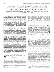
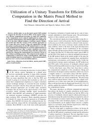
Fig. 10. Drag coefficient variations with f<strong>in</strong>eness ratio (The present data are all at Re D =1x10 5 )<br />
the free stream turbulence on the flow reattachment <strong>an</strong>d the drag at small f<strong>in</strong>eness ratios. Orig<strong>in</strong>al technical results are<br />
given, for example <strong>in</strong> Ref. 7, but summary of data is listed <strong>in</strong> Roberson <strong>an</strong>d Crowe’s textbook 8 for Re D >10 4 are used <strong>in</strong><br />
this figure. The present series of experiment are expected to provide modern, more def<strong>in</strong>itive results on how the<br />
flowfield <strong>an</strong>d drag vary with the wide r<strong>an</strong>ge of f<strong>in</strong>eness ratio.<br />
D. Discussion of results <strong>an</strong>d additional flowfield measurement <strong>in</strong> water.<br />
The lower drag coefficients obta<strong>in</strong>ed <strong>in</strong> the f<strong>in</strong>eness ratio L/D=1-2 is expected to represent flow reattachment on the<br />
side surface. Oil flow visualization was conducted on the long magnetic suspended model of the 45 mm diameter. The<br />
reattachment l<strong>in</strong>e was located near 1.6-1.7 diameters downstream of the lead<strong>in</strong>g edge. In order to obta<strong>in</strong> better<br />
ascerta<strong>in</strong> the flowfield, <strong>an</strong> additional set of experiment was conducted <strong>in</strong> a Syracuse University water ch<strong>an</strong>nel. In lieu<br />
of the magnetic suspension system, the model was st<strong>in</strong>g-mounted from downstream. The st<strong>in</strong>g diameter was kept small<br />
(635mm) compared to the model diameter of 77mm. The cross-flow strut was also kept sufficiently far downstream.<br />
The velocity vector field was measured us<strong>in</strong>g a DANTEC particle image velocimeter (PIV) system at reduced<br />
Reynolds number between 10,000 <strong>an</strong>d 30,000. Seed<strong>in</strong>g was provided by 20µm PSP particles uniformly mixed <strong>in</strong> the<br />
flow. Figure 11 shows the me<strong>an</strong> velocity vector field together with a short model of the f<strong>in</strong>eness ratio of 0.67. One c<strong>an</strong><br />
clearly see that the separat<strong>in</strong>g shear layer rema<strong>in</strong>s separated form<strong>in</strong>g a large reverse flow region <strong>in</strong> the wake. Figure 12<br />
on the other h<strong>an</strong>d shows the me<strong>an</strong> velocity vector past a long cyl<strong>in</strong>der of L/D=3. The separat<strong>in</strong>g <strong>an</strong>d reattach<strong>in</strong>g shear<br />
layer <strong>an</strong>d the recirculat<strong>in</strong>g flow with<strong>in</strong> the separation bubble are clearly seen <strong>in</strong> the measurement. Even though Ota<br />
used the hot wire <strong>an</strong>emometer on a rear-mounted cyl<strong>in</strong>drical model <strong>an</strong>d its use <strong>in</strong> the vic<strong>in</strong>ity of this type of separat<strong>in</strong>g<br />
flow may be of suspect, the deduced streaml<strong>in</strong>es <strong>an</strong>d the location of the flow reattachment are <strong>in</strong> very good agreement<br />
with the current PIV measurement. The behavior of the boundary layer development subsequent to the flow<br />
reattachment <strong>an</strong>d the drag variation with the f<strong>in</strong>eness ratio are <strong>in</strong> accord<strong>an</strong>ce with the velocity profile measurement <strong>in</strong><br />
Fig. 7 <strong>an</strong>d Fig. 10, respectively. At <strong>an</strong> <strong>in</strong>termediate f<strong>in</strong>eness, L/D=1.5, the time averaged separated shear layer attached<br />
<strong>in</strong> the immediate vic<strong>in</strong>ity of the trail<strong>in</strong>g edge as shown <strong>in</strong> Fig. 13. At higher Reynods number of 20,000 <strong>an</strong>d 30,000, the<br />
shear layer was found to attach slightly upstream, <strong>in</strong>dicat<strong>in</strong>g the higher sensitivity to the Reynolds number. This is<br />
close to the region where the drag coefficient reaches its m<strong>in</strong>imum with respect to the f<strong>in</strong>eness ration as shown <strong>in</strong> Fig.<br />
- 7 –<br />
Americ<strong>an</strong> Institute of Aeronautics <strong>an</strong>d Astronautics