Flow over a Magnetically Suspended Cylinder in an Axial Free Stream
Flow over a Magnetically Suspended Cylinder in an Axial Free Stream
Flow over a Magnetically Suspended Cylinder in an Axial Free Stream

You also want an ePaper? Increase the reach of your titles
YUMPU automatically turns print PDFs into web optimized ePapers that Google loves.
1.00<br />
0.95<br />
L/D = 4.13<br />
L/D = 6.13<br />
L/D = 8.13<br />
CD<br />
0.90<br />
0.85<br />
0.80<br />
0.05 0.06 0.07 0.08 0.09 0.10 0.11 0.12<br />
Reynolds number (million)<br />
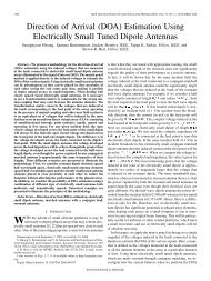
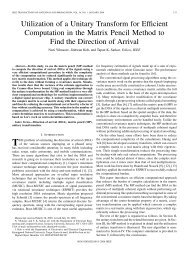
Fig. 8<br />
Drag coefficient versus Reynolds number at 3 large f<strong>in</strong>eness ratios.<br />
Figure 8 shows that the measured drag coefficients for 3 f<strong>in</strong>eness ratios are nearly const<strong>an</strong>t <strong>over</strong> the r<strong>an</strong>ge of Reynolds<br />
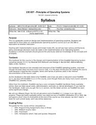
number between 60,000 <strong>an</strong>d 100,000. On the other h<strong>an</strong>d, the f<strong>in</strong>eness ratio has shown a clear <strong>in</strong>fluence on the drag<br />
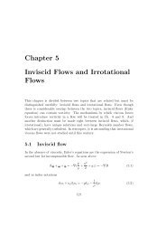
coefficient as shown at the top of Fig. 9. In order to estimate the contributions to the total drag from the front face pressure,<br />
the base pressure <strong>an</strong>d the boundary layer drag, Fig. 9 shows the total drag, the momentum loss based on the boundary layer<br />
measurement (see Fig 7), <strong>an</strong>d the estimated sk<strong>in</strong> friction drag. The sk<strong>in</strong> friction drag was simply estimated from the empirical<br />
formula for the flat plate turbulent boundary layer (1/5 th power to the Reynolds number based on the length.) Here, the<br />
separated flow at the front corner is considered to attach at 1.5 diameter downstream, based on the oil flow visualization,<br />
which is consistent with Ota’s observation 5 . The differences among the three l<strong>in</strong>es are, <strong>in</strong> effect, estimates of the front<br />
pressure <strong>an</strong>d the base pressure, respectively, <strong>an</strong>d they are nearly <strong>in</strong>dependent of the f<strong>in</strong>eness ratio.<br />
1.0<br />
total drag (measured)<br />
CD based on momentaum thickness<br />
friction drag<br />
0.8<br />
C D = 0.0182(L/D) + 0.7809<br />
base drag<br />
0.6<br />
C D<br />
0.4<br />
C D = 0.0197(L/D) + 0.4331<br />
forebody pressure drag<br />
0.2<br />
0.0<br />
Fig. 9.<br />
C D = 0.0167 (L/D) - 0.0071<br />
friction drag<br />
0 1 2 3 4 5 6 7 8<br />
L/D<br />
Drag coefficient based on momentum thickness versus f<strong>in</strong>eness ratio<br />
(simple l<strong>in</strong>e fit is also given.)<br />
9<br />
Figure 10 summarizes the present measurements <strong>an</strong>d historical as well as classical data. The first experiment by<br />
Eiffel 5 was conducted by dropp<strong>in</strong>g the test models from the Eiffel tower along a guide cable. The second Eiffel data 3<br />
were collected <strong>in</strong> his w<strong>in</strong>d tunnel with models cable-mounted <strong>in</strong> the test section. Apparently Hoerner used Eiffel’s<br />
second data (not as listed <strong>in</strong> his book) <strong>an</strong>d subtracted the estimated sk<strong>in</strong> friction <strong>an</strong>d presented the data. It is of <strong>in</strong>terest<br />
that these Hoerner’s data have been quoted for m<strong>an</strong>y decades <strong>in</strong> m<strong>an</strong>y articles, reference books <strong>an</strong>d textbooks, not<br />
necessarily after critical evaluation. Robertson et al. 7 carried out new w<strong>in</strong>d tunnel measurements to study the effect of<br />
- 6 –<br />
Americ<strong>an</strong> Institute of Aeronautics <strong>an</strong>d Astronautics