Flow over a Magnetically Suspended Cylinder in an Axial Free Stream
Flow over a Magnetically Suspended Cylinder in an Axial Free Stream
Flow over a Magnetically Suspended Cylinder in an Axial Free Stream

You also want an ePaper? Increase the reach of your titles
YUMPU automatically turns print PDFs into web optimized ePapers that Google loves.
(y - D/2)/delta<br />
2.0<br />
1.5<br />
1.0<br />
0.5<br />
L/D=4.13 (45Dia.) delta=32.5mm<br />
L/D=5.02 (45Dia.) delta=32.5mm<br />
L/D=6.00 (25Dia.) delta=19.0mm<br />
L/D=8.13 (45Dia.) delta=41.0mm<br />
0.2<br />
0.0<br />
0 0 0 0 1 1 1 1<br />
u/U<br />
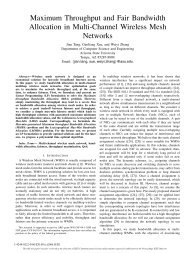
Figure 6. u/U vs.[y-(D/2)]/δ, effect of f<strong>in</strong>eness ratio)<br />
(Re D =50,000 for 25mm dia, 100,000 for 45mm dia.)<br />
2.0<br />
1.5<br />
L/D=4.13 (45Dia.) delta=32.5mm<br />
L/D=5.02 (45Dia.) delta=32.5mm<br />
L/D=6.00 (25Dia.) delta=19.0mm<br />
L/D=8.13 (45Dia.) delta=41.0mm<br />
(y - D/2)/delta<br />
1.0<br />
0.2<br />
0.5<br />
0.0<br />
0 0 0 0<br />
0.8<br />
u rms /U<br />
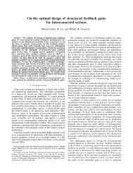
Figure 7. u rms /U vs. .[y-(D/2)]/δ, effect of f<strong>in</strong>eness ratio<br />
The boundary layer leav<strong>in</strong>g the cyl<strong>in</strong>der at the trail<strong>in</strong>g edge was further <strong>in</strong>vestigated for various f<strong>in</strong>eness ratios.<br />
The me<strong>an</strong> velocity profiles <strong>an</strong>d the turbulence <strong>in</strong>tensity normalizes by the boundary layer thickness are shown <strong>in</strong> Fig.<br />
6 <strong>an</strong>d Fig. 9, respectively. Ota 4 <strong>in</strong>vestigated the boundary layer <strong>over</strong> a st<strong>in</strong>g-mounted sharp-edged cyl<strong>in</strong>der, <strong>an</strong>d his<br />
velocity profiles at x/D=3.1, 5.1, <strong>an</strong>d 7.1 from the lead<strong>in</strong>g edge are very consistent with the present data at the<br />
trail<strong>in</strong>g edge (L/D=4.13-8.13). Ota’s experiment corresponds to Re D =5.62x10 4 <strong>an</strong>d the Reynolds number for the<br />
measurements <strong>in</strong> Figs. 6 <strong>an</strong>d 7 was 5x10 4 for the 25mm cyl<strong>in</strong>der <strong>an</strong>d 1x10 5 for the 45mm cyl<strong>in</strong>der. The oil flow<br />
visualization <strong>an</strong>d Ota’s measurement <strong>in</strong>dicated a separation bubble from the lead<strong>in</strong>g edge end<strong>in</strong>g with flow<br />
reattachment approximately at 1.5-1.6 diameter downstream. The me<strong>an</strong> velocity profiles further downstream of the<br />
reattachment are <strong>in</strong>dicative of a develop<strong>in</strong>g turbulent boundary layer. The turbulent <strong>in</strong>tensity profiles are also <strong>in</strong><br />
general agreement between the two experiments, though the present data are at a somewhat higher level. The power<br />
spectrum density <strong>in</strong> the immediate wake shear layer showed the distribution typical of turbulent boundary layer<br />
devoid of <strong>an</strong>y spectral peak, but at x/D=4, a spectral peak was evident at Strouhal number fD/U=0.185 which was<br />
<strong>in</strong>dicative of a helical mode wake oscillation.<br />
C. Force Measurement<br />
The magnetic bal<strong>an</strong>ce was calibrated aga<strong>in</strong>st the known weight for each model. The uncerta<strong>in</strong>ty of the drag<br />
coefficient measurement at Reynolds number 10 5 , for example, was estimated to be ±0.005.<br />
- 5 –<br />
Americ<strong>an</strong> Institute of Aeronautics <strong>an</strong>d Astronautics