Robinair 34134-2K 134a Recovery Unit - NY Tech Supply
Robinair 34134-2K 134a Recovery Unit - NY Tech Supply
Robinair 34134-2K 134a Recovery Unit - NY Tech Supply

Create successful ePaper yourself
Turn your PDF publications into a flip-book with our unique Google optimized e-Paper software.
○ ○ ○ ○ ○ ○ ○ ○ ○ ○ ○ ○ ○ ○ ○ ○ ○ ○ ○ ○ ○ ○ ○ ○ ○ ○ ○ ○ ○ ○ ○ ○ ○ ○ ○ ○ ○ ○ ○ ○ ○ ○ ○ ○ ○ ○ ○ ○ ○ ○ ○ ○ ○ ○ ○ ○ ○ ○ ○ ○ ○ ○ ○ ○ ○ ○ ○ ○ ○ ○ ○ ○ ○ ○ ○<br />
Operating<br />
Manual<br />
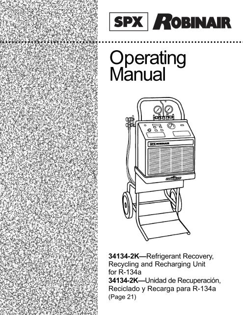
<strong>34134</strong>-<strong>2K</strong>—Refrigerant <strong>Recovery</strong>,<br />
Recycling and Recharging <strong>Unit</strong><br />
for R-<strong>134a</strong><br />
<strong>34134</strong>-<strong>2K</strong>—Unidad de Recuperación,<br />
Reciclado y Recarga para R-<strong>134a</strong><br />
(Page 21)
LISTED<br />
80S2<br />
Recycling Equipment Design<br />
Certified by Underwriters<br />
Laboratories Inc.® for<br />
Compliance with SAE-J2210<br />
(1991) for HFC-<strong>134a</strong><br />
Refrigerant <strong>Recovery</strong>,<br />
Recycling and Recharging Station<br />
Series: <strong>34134</strong>-<strong>2K</strong><br />
Refrigerants: R-<strong>134a</strong><br />
SAFETY DEFINITIONS: Follow all WARNING, CAUTION, IMPORTANT, and NOTE messages in this manual. These<br />
messages are defined as follows: WARNING means you may risk serious personal injury or death; CAUTION means<br />
you may risk personal injury, property damage, or serious unit damage; IMPORTANT means you may risk unit damage;<br />
and NOTEs provide clarity and helpful tips. These safety messages cover situations ROBINAIR is aware of. ROBINAIR<br />
cannot know, evaluate, and advise you as to all possible hazards. You must make sure all conditions and procedures do<br />
not jeopardize your personal safety.<br />
COPYRIGHT: No part of this manual may be reproduced, stored in a retrieval system, or transmitted in any form or by<br />
any means (electronic, mechanical, photocopy, recorded, or otherwise) without the prior written permission of ROBINAIR.<br />
DISCLAIMER: All information, illustrations, and specifications contained in this manual are based on the latest<br />
information available at the time of publication. The right is reserved to make changes at any time without obligation to<br />
notify any person or organization of such revisions or changes. Further, ROBINAIR shall not be liable for errors contained<br />
herein or for incidental or consequential damages (including lost profits) in connection with the furnishing, performance, or<br />
use of this material. If necessary, obtain additional health and safety information from the appropriate government<br />
agencies and the vehicle, refrigerant, and lubricant manufacturers.<br />
WARNINGS<br />
ALLOW ONLY QUALIFIED PERSONNEL TO OPERATE THE UNIT. Before operating the unit, read and follow<br />
the instructions and warnings in this manual. The operator must be a certified technician and must be familiar with<br />
air conditioning and refrigeration systems, refrigerants, and the dangers of pressurized components. If the<br />
operator cannot read English, operating instructions and safety precautions must be read and discussed in the<br />
operator’s native language.<br />
Si el operador no puede leer el inglés, las instrucciones de operación y las precauciones de seguridad deberán<br />
leerse y comentarse en el idioma nativo del operador.<br />
Si l’utilisateur ne peut lire l’anglais, les instructions et les consignes de sécurité doivent lui être expliquées dans sa<br />
langue maternelle.<br />
PRESSURIZED TANK CONTAINS LIQUID REFRIGERANT. Do not overfill the internal storage vessel because<br />
overfilling may cause explosion and serious personal injury or death. Do not recover or charge refrigerants into<br />
non-refillable containers; use only federally authorized refillable containers.<br />
ALL HOSES MAY CONTAIN LIQUID REFRIGERANT UNDER PRESSURE. Contact with refrigerant may cause<br />
personal injury. Wear correct protective equipment, including safety goggles. Disconnect hoses with extreme<br />
caution.<br />
HIGH VOLTAGE ELECTRICITY INSIDE THE UNIT HAS A RISK OF ELECTRICAL SHOCK. Exposure may<br />
cause personal injury. Refer to the instruction manual for correct procedure when disconnecting the power.<br />
TO REDUCE THE RISK OF FIRE, do not use the unit in the vicinity of spilled or open containers of gasoline or<br />
other flammable substances. An extension cord may overheat and cause fire. If an extension cord is needed, use<br />
the shortest possible cord with a minimum size of No. 14 AWG.<br />
DO NOT BREATH REFRIGERANT. Exposure may cause personal injury, especially to the eyes, nose, throat, and<br />
lungs. Use this equipment in locations with mechanical ventilation that provides at least four air changes per hour<br />
or locate the equipment at least 18 inches above the floor. If accidental system discharge occurs, ventilate the<br />
work area before resuming service.<br />
USE THE UNIT WITH ONLY R-<strong>134a</strong> REFRIGERANT. The unit is for recovering, recycling, and recharging only<br />
R-<strong>134a</strong> refrigerant! Do not attempt to adapt the unit for another refrigerant. Do not mix refrigerant types through a<br />
system or in the same container; mixing of refrigerants will cause severe damage to the unit and the vehicle air<br />
conditioning system.<br />
DO NOT USE COMPRESSED AIR TO PRESSURE TEST OR LEAK TEST THE UNIT OR VEHICLE AIR<br />
CONDITIONING SYSTEM. Some mixtures of air and R-<strong>134a</strong> refrigerant are combustible at elevated pressures.<br />
These mixtures are potentially dangerous and may result in fire or explosion causing personal injury or property<br />
damage.<br />
Additional health and safety information may be obtained from refrigerant and lubricant manufacturers.<br />
This equipment is protected by one or more of the following patents: US: 4,938,031; 5,005,369; 5,248,125; 4,261,178;<br />
4,768,347. Other U.S. and Foreign Patents Pending.
Introduction ........................................................................................................... 2<br />
Glossary of Terms ........................................................................................... 2<br />
Operating Tips ................................................................................................. 3<br />
Table of Contents<br />
Using The Control Panel ................................................................................. 4<br />
Component Location and Identification ........................................................... 5<br />
Set-Up Instructions................................................................................................ 6<br />
Installing the Tank ........................................................................................... 6<br />
English<br />
Setting up the <strong>Unit</strong> ........................................................................................... 7<br />
Adding Refrigerant to the <strong>Unit</strong> Tank ................................................................ 8<br />
Operating Instructions ........................................................................................... 9<br />
Recovering Refrigerant ................................................................................... 9<br />
Evacuating the A/C System ............................................................................ 9<br />
Air Purge ....................................................................................................... 10<br />
Recharging the A/C System .......................................................................... 10<br />
Maintenance Instructions .................................................................................... 11<br />
Checking and Calibrating the Scale .............................................................. 11<br />
Español<br />
Replacing the Filter-Drier .............................................................................. 12<br />
Checking and Resetting Filter Capacity ........................................................ 13<br />
Checking for Leaks ....................................................................................... 13<br />
Choosing the Temperature Scale ................................................................. 13<br />
Troubleshooting Tips........................................................................................... 14<br />
Vacuum Flow Diagram ........................................................................................ 15<br />
Recover Flow Diagram........................................................................................ 16<br />
Charge Flow Diagram ......................................................................................... 17<br />
Replacement Parts.............................................................................................. 18<br />
Limited Warranty ................................................................................................. 19<br />
Pressure/Temperature Chart .....................................................Inside Back Cover<br />
<strong>34134</strong>-<strong>2K</strong> <strong>Recovery</strong>, Recycling and Recharging <strong>Unit</strong><br />
1
Introduction<br />
This manual contains important safety procedures concerning the operation,<br />
use and maintenance of this product. Failure to follow the instructions<br />
contained in this manual may result in serious injury. If you are unable to<br />
understand any of the contents of this manual, please bring it to the<br />
attention of your supervisor. Do not operate this equipment unless you have<br />
read and understood the contents of this manual.<br />
The <strong>34134</strong>-<strong>2K</strong> <strong>Recovery</strong>, Recycling and Recharging unit is a one hook-up system<br />
used for R-<strong>134a</strong> vehicles. This single-pass system is UL listed and meets the SAE<br />
specifications for recycled refrigerant. It is also designed to be compatible with<br />
existing service equipment and standard service procedures.<br />
The <strong>34134</strong>-<strong>2K</strong> is simple to operate and has many user-friendly features:<br />
• Hose holder rack<br />
• Large diameter wheels for easy relocation<br />
• Plastic shroud that is resistant to abrasions and chemicals<br />
• Handy manifold gauge set<br />
GLOSSARY OF TERMS<br />
A/C System The air conditioning system being serviced.<br />
<strong>Unit</strong><br />
The refrigerant recovery/recycling/recharging unit.<br />
<strong>Unit</strong> Tank The refillable refrigerant tank included with this unit.<br />
Source Tank A supply of refrigerant used to refill the unit tank.<br />
2<br />
© 2000 <strong>Robinair</strong>, SPX Corporation
Introduction<br />
Low Side Gauge<br />
High Side Gauge<br />
Low Side Valve<br />
(Blue)<br />
High Side Valve<br />
(Red)<br />
INST0488<br />
Low Side Port<br />
Center Port<br />
High Side Port<br />
OPERATING TIPS<br />
Follow the SAE-J2210 recommended service procedures for the containment<br />
of R-<strong>134a</strong>.<br />
R-<strong>134a</strong> systems require special oils in place of the mineral oil used with R-12<br />
systems. Refer to the A/C system manufacturer’s service manuals for oil<br />
specifications.<br />
Change the filter-drier when the display shows “CHANGE FILTER.” Follow the<br />
instructions for changing the filter-drier.<br />
Wait 10 minutes between recovery jobs when temperatures exceed 120°F / 49°C.<br />
CAUTION! R-<strong>134a</strong> systems have special fittings (per SAE specifications)<br />
to avoid cross-contamination with R-12 systems. Do not attempt to adapt your<br />
unit for another refrigerant type—system failure will result!<br />
<strong>34134</strong>-<strong>2K</strong> <strong>Recovery</strong>, Recycling and Recharging <strong>Unit</strong><br />
3
Introduction<br />
USING THE CONTROL PANEL<br />
The control panel has the following specific operating functions:<br />
1. RECOVER/VACUUM Switch — Starts the recovery or vacuum process.<br />
2. TARE Button — Zeros the display weight prior to recovery or charging.<br />
3. LB/KG Button — Toggles between the weight measurement units.<br />
4. CHARGE Button — Controls the charging process.<br />
5. AIR PURGE Button — Controls the air purge process.<br />
6. TEMPERATURE Display — Indicates tank temperature.<br />
7. COMPRESSOR ON Light — Indicates compressor has started.<br />
8. PRESSURE Gauge — Indicates the tank pressure.<br />
9. CONTROL BOARD Display — Indicates refrigerant weight and error messages.<br />
INST 0754<br />
4<br />
© 2000 <strong>Robinair</strong>, SPX Corporation
COMPONENT LOCATION AND IDENTIFICATION<br />
Introduction<br />
Front View<br />
Rear View<br />
Power<br />
Receptacle<br />
Manifold valves<br />
Heater<br />
Outlet<br />
Access Port<br />
Heater<br />
Circuit Breaker<br />
Oil Drain Valve<br />
Oil Drain Bottle<br />
Scale Assembly<br />
INST 0755 INST 0756<br />
<strong>34134</strong>-<strong>2K</strong> <strong>Recovery</strong>, Recycling and Recharging <strong>Unit</strong><br />
5
Set-Up Instructions<br />
INSTALLING THE TANK<br />
The new tank comes with a dry nitrogen charge of 10 to 15 psi (4.9 to 7.4 bar) to<br />
keep it clean and dry during shipment. To install the new tank, you will need to:<br />
1. Purge its nitrogen charge by opening either valve on the tank, vent the pressure<br />
to the atmosphere, then close the valve.<br />
2. Place the unit tank on the scale platform on the back of the unit (see illustration<br />
on page 5 for location). Then attach the tank strap to the tank handle.<br />
3. Attach the temperature probe at the approximate location shown below.<br />
CAUTION! Some tanks have slightly different valve configurations. Be sure to<br />
connect the VAPOR hose to the GAS (vapor) valve and connect the LIQUID hose to<br />
the LIQUID valve.<br />
Valve ports<br />
Valves:<br />
Blue Liquid Valve<br />
Red Vapor Valve<br />
t<br />
5cm (2 in.)<br />
s<br />
Temperature<br />
Probe<br />
INST 0494<br />
6<br />
© 2000 <strong>Robinair</strong>, SPX Corporation
Set-Up Instructions<br />
SETTING UP THE UNIT<br />
To set up the unit to an R-<strong>134a</strong> vehicle:<br />
1. Attach the 60" blue hose to the low side port of the manifold.<br />
2. Attach the 60" yellow hose to the center port of the manifold.<br />
3. Attach the 60" red hose to the high side port of the manifold.<br />
4. Place the assembled manifold onto the manifold support bracket on the back<br />
of the unit.<br />
5. Attach the yellow hose from the manifold to the access port on the back of the<br />
unit.<br />
6. Connect the tank adapter (included with the unit) to the LIQUID port (blue)<br />
of the tank. Attach the blue low side hose from the manifold to the tank<br />
adapter.<br />
NOTE: Use ONLY the tank adapter included with this unit. Use of any other<br />
adapter could result in damage to the compressor, voiding the manufacturer's<br />
warranty.<br />
7. Attach the red vapor hose from the back of the unit to the GAS (red vapor)<br />
valve on the tank.<br />
8. Attach the air purge hose to the air purge fitting on the unit tank.<br />
9. Open both valves on the manifold.<br />
10. Open both valves on the tank.<br />
11. Open the service coupler on the blue low side hose.<br />
12. Verify that the RECOVER/VACUUM switch (see page 4 for switch location)<br />
is in the OFF position.<br />
13. Attach the power cord to the back of the unit (see page 5) and connect to the<br />
correct voltage outlet on the vehicle.<br />
14. Turn the switch on the control panel to VACUUM.<br />
15. Allow the unit to run for 5 minutes.<br />
16. Turn the RECOVER/VACUUM switch to OFF.<br />
17. Close the high side manifold valve (red).<br />
18. Close the service coupler valve on the blue low side hose.<br />
19. Close the LIQUID valve (blue) on the tank.<br />
20. Disconnect the service coupler from the tank adapter.<br />
21. Remove the tank adapter from the tank.<br />
22. Attach LIQUID hose from the back of the unit to LIQUID port on the tank.<br />
Open the LIQUID valve on the tank.<br />
23. Reconnect the tank adapter to the hose holder for storage.<br />
<strong>34134</strong>-<strong>2K</strong> <strong>Recovery</strong>, Recycling and Recharging <strong>Unit</strong><br />
7
Set-Up Instructions<br />
ADDING REFRIGERANT TO THE UNIT TANK<br />
With the tank in place on the unit, add refrigerant from a source tank to the unit<br />
tank using the following steps:<br />
1. Connect the tank adapter to the LIQUID valve on the source tank. Attach the<br />
blue low side service coupler to the tank adapter.<br />
NOTE: Use ONLY the tank adapter included with this unit. Use of any other could<br />
result in damage to the compressor, voiding the manufacturer's warranty.<br />
2. Open the service coupler valve. Open the LIQUID valve on the source tank.<br />
NOTE: Disposable tanks have only one valve and must be turned upside down to<br />
transfer liquid.<br />
3. Press the TARE button (see page 4 for button location) on the control panel to<br />
zero the tare weight.<br />
4. Turn the control panel switch to RECOVER. Monitor the display until 15 lbs.<br />
(6.8 kg) have been transferred.<br />
5. Close the blue LIQUID valve on the source tank. Allow the unit to run for 5<br />
minutes to clear the hoses.<br />
6. Turn the RECOVER/VACUUM switch to OFF.<br />
7. Close both manifold valves (see page 5 for manifold location).<br />
8. Disconnect the service coupler from the tank adapter.<br />
9. Remove the adapter from the tank.<br />
10. Reconnect the tank adapter to the hose holder for storage.<br />
8<br />
© 2000 <strong>Robinair</strong>, SPX Corporation
Operating Instructions<br />
RECOVERING REFRIGERANT<br />
Use the following steps to take refrigerant out of a vehicle:<br />
1. Connect the unit’s 60" (1.5m) red high side hose with the service coupler to<br />
the high side fitting of the A/C system, then open the service coupler valve.<br />
2. Connect the unit’s 60" (1.5m) blue low side hose with the service coupler to<br />
the low side fitting of the A/C system, then open the service coupler valve.<br />
3. Check the manifold gauges — both should register above zero. If there is no<br />
system pressure, there is no refrigerant in the system to recover.<br />
4. Be sure the oil drain valve (see page 5 for oil drain valve location) is closed.<br />
5. Open both manifold valves.<br />
6. Verify both tank valves are open.<br />
7. Plug the unit into the correct voltage outlet.<br />
8. Turn the control panel switch to RECOVER. Recover refrigerant until the low<br />
side manifold gauge reads 13 in. Hg (0.44 Bar).<br />
9. Close both manifold valves.<br />
10. Turn the RECOVER/VACUUM switch to OFF.<br />
11. Wait 5 minutes. Monitor the manifold gauges for a pressure rise above zero. If<br />
a rise occurs, repeat steps 5 – 10.<br />
CAUTION! Drain the oil from the separator only after each recovery. Do not<br />
depressurize the oil separator.<br />
12. Be sure the oil catch bottle is empty, then slowly open the oil drain valve, and<br />
drain the oil into the oil catch bottle. This oil was removed from the A/C<br />
system during recovery. When all the recovered oil has completely drained,<br />
close the valve and record the amount of oil in the bottle.<br />
The A/C system is empty. Make any repairs at this time.<br />
EVACUATING THE A/C SYSTEM<br />
To ensure complete evacuation of the A/C system, use the following steps:<br />
1. With the high side and low side hoses connected to the A/C system, open both<br />
manifold valves.<br />
2. Verify both tank valves are open.<br />
3. Turn the control panel switch to VACUUM. Follow the manufacturer's<br />
recommendations for evacuation time.<br />
4. Turn the RECOVER/VACUUM switch to OFF.<br />
5. Wait 5 minutes. Monitor the manifold gauges. Any rise indicates a leak in the<br />
A/C system. Locate and repair. Repeat steps 3 – 5 until there is no longer a<br />
rise on the gauges.<br />
<strong>34134</strong>-<strong>2K</strong> <strong>Recovery</strong>, Recycling and Recharging <strong>Unit</strong><br />
9
Operating Instructions<br />
AIR PURGE<br />
! !<br />
The gauge on the control panel shows when to purge air from the tank. To purge<br />
non-condensables:<br />
1. Check the TEMPERATURE display (see page 4) to find the temperature of<br />
the refrigerant in the unit tank.<br />
2. Use this temperature to find the correct pressure for the refrigerant on the<br />
appropriate pressure/temperature chart on the control panel.<br />
3. Compare the pressure from the chart to the reading on the tank pressure<br />
gauge.<br />
4. If the pressure exceeds the target pressure by more than 10 psi (0.7 Bar), press<br />
the air purge button for approximately 30 seconds.<br />
5. Check tank pressure and repeat steps as necessary.<br />
RECHARGING THE A/C SYSTEM<br />
10<br />
To recharge A/C system:<br />
1. Connect the high side and low side hoses to the A/C system according to its<br />
manufacturer's recommendations for charging. Open appropriate service<br />
coupler and manifold valve(s).<br />
2. Verify both tank valves are open.<br />
3. Press TARE button until “00.00” weight is displayed.<br />
4. Determine the amount of charge needed from the vehicle nameplate. Press<br />
and hold the CHARGE button until the desired weight charge is indicated on<br />
the display. Release the CHARGE button.<br />
5. Close both manifold valves.<br />
6. Start the vehicle's engine and turn on the A/C system for maximum cooling.<br />
Let it run until the gauge pressure readings stabilize. Compare the gauge<br />
readings with the system manufacturer's specifications.<br />
7. Check the evaporator outlet temperature to be sure that the A/C system is<br />
operating correctly. Refer to the system manufacturer's specifications for the<br />
correct temperature.<br />
8. Turn off the vehicle's engine.<br />
9. Close the high side coupler valve, then disconnect the high side hose from the<br />
A/C system.<br />
10. Restart the vehicle, then open both valves on the manifold. Refrigerant from<br />
both hoses will be drawn quickly into the A/C system through the low side<br />
hose.<br />
11. Close the low side coupler valve, then disconnect the low side hose from the<br />
A/C system.<br />
12. Turn off the vehicle engine.<br />
13. Close both manifold valves.<br />
NOTE: If using the optional heating blanket, make sure the blanket is far enough away<br />
from the temperature probe not to interfere with temperature probe accuracy.<br />
© 2000 <strong>Robinair</strong>, SPX Corporation
Maintenance<br />
CHECKING AND CALIBRATING THE SCALE<br />
To check and calibrate the unit’s scale:<br />
1. Remove the tank from the platform.<br />
2. Press the TARE button (see page 4) until the display reads “00.00.”<br />
3. Press the TARE button once more. The display reads “TOTAL” and “0+ .10.”<br />
4. Place a known weight on the scale. The display will show the known weight<br />
“+ .04 LB/.02 KG.”<br />
5. If the display does not, recalibrate the scale.<br />
6. To recalibrate, press the TARE and LB/KG buttons simultaneously to access<br />
“DIAGNOSTICS.”<br />
7. Press the TARE button until the display shows “CALIBRATION.”<br />
8. Press LB/KG. Press YES (TARE) to continue or NO (LB/KG) to return to<br />
main menu.<br />
9. With no weight on the platform, press LB/KG. The display shows “30 LB/15<br />
KG.” Place the indicated weight on the platform.<br />
NOTE: This weight must be EXACT for accurate scale calibration.<br />
10. Press LB/KG. “PLEASE WAIT” shows on the display for approximately 10<br />
seconds.<br />
11. Reverify scale accuracy.<br />
IMPORTANT!<br />
You must have a<br />
known weight of<br />
15KG +.005<br />
(30LB + .01)<br />
<strong>34134</strong>-<strong>2K</strong> <strong>Recovery</strong>, Recycling and Recharging <strong>Unit</strong><br />
11
Maintenance<br />
REPLACING THE FILTER-DRIER<br />
The filter-drier on this unit is designed to trap acid, and particulates and is formulated<br />
to remove moisture from the refrigerant. Typically, you can recover up to<br />
300 pounds of refrigerant between filter changes.<br />
CAUTION! For best results, use a <strong>Robinair</strong> filter-drier (part no.<br />
34430). All performance tests and claims are based on using this<br />
specially-blended filter-drier. Use of any other may affect performance<br />
results.<br />
WARNING<br />
Steps 1 – 5 are critical to avoid possible hazardous release of refrigerant!<br />
Filter-Drier<br />
INST 0757<br />
1. Make sure both tank valves and manifold valves are open.<br />
2. Make sure the service couplers are closed.<br />
3. Turn control panel switch to RECOVER.<br />
4. Monitor manifold gauges until pressure reads below zero.<br />
5. Turn RECOVER/VACUUM switch to OFF.<br />
6. Remove filter by unscrewing nuts located at each end of the filter. Dispose of<br />
the old filter according to all local and state regulations.<br />
7. Inspect the condition of the gaskets inside the copper tubes that are connected<br />
to the filter. Install new filter and hand tighten.<br />
8. Turn the control panel switch to VACUUM for 5 minutes.<br />
9. Turn RECOVER/VACUUM switch to OFF.<br />
NOTE: Following filter-drier replacement, the filter capacity must be reset.<br />
12<br />
© 2000 <strong>Robinair</strong>, SPX Corporation
CHECKING AND RESETTING FILTER CAPACITY<br />
Maintenance<br />
The filter-drier removes contaminants from the refrigerant. To check and reset the<br />
filter capacity:<br />
1. Turn the RECOVER/VACUUM switch on the control panel to OFF.<br />
2. Press LB/KG and the TARE buttons (see page 4 for button locations) simultaneously<br />
to access “DIAGNOSTICS.”<br />
3. Press the TARE button until the display reads “FILTER CAPACITY.”<br />
4. Press the LB/KG button. The display will show the filter capacity remaining in<br />
the selected weight measurement.<br />
5. To reset the capacity, press the TARE and LB/KG buttons simultaneously.<br />
The display will show “300 LB/136 KG” remaining.<br />
6. Press any button to exit “DIAGNOSTICS.”<br />
CHECKING FOR LEAKS<br />
Every three months, or as specified by local or state laws, you should check your<br />
unit for leaks. To check for leaks:<br />
1. Disconnect the power cord from the outlet.<br />
2. Remove the shroud by removing the threaded screws at the back of the unit.<br />
3. Use a leak detector to probe all fitting connections for refrigerant leaks.<br />
Tighten fittings if a leak is indicated.<br />
4. Reassemble the shroud to the unit, replacing all screws.<br />
IMPORTANT!<br />
Inspect the unit<br />
periodically for<br />
leaks. The manufacturer<br />
does not<br />
reimburse for<br />
lost refrigerant.<br />
CHOOSING THE TEMPERATURE SCALE<br />
The temperature scale may be changed from Fahrenheit or Centigrade using the<br />
following procedure.<br />
1. Disconnect the power cord from the outlet.<br />
2. Remove the shroud by removing the threaded screws at the back of the unit.<br />
3. A small selector switch is located on the back of the thermometer. Change the<br />
position of the switch to change the temperature scale from either Fahrenheit<br />
or Centigrade.<br />
4. Reassemble the shroud to the unit, replacing all screws.<br />
<strong>34134</strong>-<strong>2K</strong> <strong>Recovery</strong>, Recycling and Recharging <strong>Unit</strong><br />
13
Troubleshooting Tips<br />
RECOVERY AND VACUUM OPERATION<br />
Compressor does not start or stop prematurely<br />
Problem:<br />
Solution:<br />
No power.<br />
Check for power at plug or outlet.<br />
Problem:<br />
Solution:<br />
**OVERLOAD** is displayed.<br />
Move refrigerant from unit tank to approved refrigerant storage<br />
tank. See RECHARGING A/C SYSTEM.<br />
Problem:<br />
Solution:<br />
HIGH PRESSURE is displayed.<br />
Be sure tank valves are open and hoses are correctly connected<br />
to the unit tank.<br />
Problem:<br />
Solution:<br />
**SCALE** is displayed.<br />
The scale is damaged, disconnected, out of calibration or overloaded.<br />
Runs but gauges won't indicate 13 in Hg (0.44 BAR)<br />
Problem:<br />
Solution:<br />
Oil drain valve open.<br />
Close the oil drain valve.<br />
Problem:<br />
Solution:<br />
Leak in vehicle system.<br />
Locate and repair all system leaks.<br />
Problem:<br />
Solution:<br />
Manifold valves not open.<br />
Open valves.<br />
14<br />
© 2000 <strong>Robinair</strong>, SPX Corporation
Vacuum Flow Diagram<br />
TO LOW SIDE<br />
TO HIGH SIDE<br />
PURGE<br />
OIL RETURN<br />
CHARGE<br />
VACUUM<br />
RECOVER<br />
INST 0748<br />
1. Refrigerant Tank<br />
2. Compressor<br />
3. Filter<br />
4. Condenser Coil<br />
5. Accumulator<br />
6. Oil Separator<br />
7. Pressure Switch<br />
8. 2-Way Manifold<br />
9. Check Valve<br />
10. Oil Drain Ball Valve<br />
11. Pressure Gauge (Air Purge)<br />
12. Thermometer F°/C°<br />
13. Solenoid Block<br />
14. Fan<br />
<strong>34134</strong>-<strong>2K</strong> <strong>Recovery</strong>, Recycling and Recharging <strong>Unit</strong><br />
15
Recover Flow Diagram<br />
TO LOW SIDE<br />
TO HIGH SIDE<br />
PURGE<br />
OIL RETURN<br />
CHARGE<br />
VACUUM<br />
RECOVER<br />
INST 0749<br />
1. Refrigerant Tank<br />
2. Compressor<br />
3. Filter<br />
4. Condenser Coil<br />
5. Accumulator<br />
6. Oil Separator<br />
7. Pressure Switch<br />
8. 2-Way Manifold<br />
9. Check Valve<br />
10. Oil Drain Ball Valve<br />
11. Pressure Gauge (Air Purge)<br />
12. Thermometer F°/C°<br />
13. Solenoid Block<br />
14. Fan<br />
16<br />
© 2000 <strong>Robinair</strong>, SPX Corporation
Charge Flow Diagram<br />
TO LOW SIDE<br />
TO HIGH SIDE<br />
PURGE<br />
OIL RETURN<br />
CHARGE<br />
VACUUM<br />
RECOVER<br />
INST 0750<br />
1. Refrigerant Tank<br />
2. Compressor<br />
3. Filter<br />
4. Condenser Coil<br />
5. Accumulator<br />
6. Oil Separator<br />
7. Pressure Switch<br />
8. 2-Way Manifold<br />
9. Check Valve<br />
10. Oil Drain Ball Valve<br />
11. Pressure Gauge (Air Purge)<br />
12. Thermometer F°/C°<br />
13. Solenoid Block<br />
14. Fan<br />
<strong>34134</strong>-<strong>2K</strong> <strong>Recovery</strong>, Recycling and Recharging <strong>Unit</strong><br />
17
Replacement Parts List<br />
The following is a list of replacement parts and accessories you may need to service<br />
or maintain your unit. We suggest you keep several filter-driers on hand so you will<br />
always be able to change them and complete any recycling job that is in progress.<br />
Component<br />
110-Volt<br />
Filter-Drier 34430<br />
Low Side Service Coupler<br />
18190A<br />
High Side Service Coupler<br />
18191A<br />
60 in. (1.52m) Red Hose 63060<br />
60 in. (1.52m) Blue Hose 62060<br />
60 in. (1.52m) Yellow Hose 61060<br />
18<br />
© 2000 <strong>Robinair</strong>, SPX Corporation
Limited Warranty<br />
This product is warranted to be free from defects in workmanship, materials, and<br />
components for a period of one year from date of purchase. All parts and labor<br />
required to repair defective products covered under the warranty will be at no<br />
charge. The following restrictions apply:<br />
1. The limited warranty applies to the original purchaser only.<br />
2. The warranty applies to the product in normal usage situations only, as<br />
described in the Operating Manual. The product must also be serviced<br />
and maintained as specified.<br />
3. If the product fails, it will be repaired or replaced at the option of the<br />
manufacturer.<br />
4. Warranty service claims are subject to factory inspection for product<br />
defect(s).<br />
5. The manufacturer shall not be responsible for any additional costs associated<br />
with a product failure including, but not limited to, loss of work time,<br />
loss of refrigerant, and un-authorized shipping and/or labor charges.<br />
6. All warranty service claims must be made within the specified warranty<br />
period. Proof-of-purchase date must be supplied to the manufacturer.<br />
7. Use of this equipment with unauthorized refrigerants will void the<br />
warranty. Authorized refrigerants are listed on the equipment or are<br />
available through our service centers.<br />
This Limited Warranty does not apply if:<br />
• The product, or product part, is broken by accident.<br />
• The product is misused, tampered with, or modified.<br />
• The product is used for recovering or recycling any substance other<br />
than the specified refrigerant type.<br />
<strong>34134</strong>-<strong>2K</strong> <strong>Recovery</strong>, Recycling and Recharging <strong>Unit</strong><br />
19
Notes<br />
20<br />
© 2000 <strong>Robinair</strong>, SPX Corporation