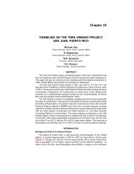
New Irvington Tunnel Design Challenges - Jacobs Associates
New Irvington Tunnel Design Challenges - Jacobs Associates
New Irvington Tunnel Design Challenges - Jacobs Associates

You also want an ePaper? Increase the reach of your titles
YUMPU automatically turns print PDFs into web optimized ePapers that Google loves.
Glenn Boyce<br />
<strong>Jacobs</strong> <strong>Associates</strong>, San Francisco, California, USA<br />
Steve Klein<br />
<strong>Jacobs</strong> <strong>Associates</strong>, San Francisco, California, USA<br />
Yiming Sun<br />
<strong>Jacobs</strong> <strong>Associates</strong>, San Francisco, California, USA<br />
Theodore Feldsher<br />
URS Corporation, Oakland, California, USA<br />
<strong>New</strong> <strong>Irvington</strong> <strong>Tunnel</strong> <strong>Design</strong> <strong>Challenges</strong><br />
David Tsztoo<br />
San Francisco Public Utilities Commission, San Francisco, California, USA<br />
ABSTRACT: The San Francisco Public Utilities Commission (SFPUC) is designing the 5.6-km-long (3.5-mi-long)<br />
<strong>New</strong> <strong>Irvington</strong> <strong>Tunnel</strong> from the Sunol Valley to the City of Fremont in Alameda County, California, with a<br />
minimum finished diameter of 2.6 m (8.5 ft). The tunnel will have a two-pass lining system―an initial support<br />
system (such as steel sets) and a final lining consisting of steel pipe, concrete pipe, or cast-in-place concrete. Ground<br />
conditions are anticipated to be difficult and highly variable, with groundwater heads of 113 m (370 ft) and potential<br />
inflows as high as 95 L/sec (1,500 gpm). This paper discusses some of the issues faced during design of the tunnel,<br />
including potential risks associated with construction.<br />
PROJECT DESCRIPTION<br />
The existing <strong>Irvington</strong> <strong>Tunnel</strong> (EIT) was constructed between 1928 and 1931 and extends approximately 5.6 km<br />
(3.5 mi) from the Sunol Valley to Fremont in Alameda County, California. The tunnel has a finished diameter of 3.2<br />
m (10.5 ft). The east end connects with the Alameda Creek Siphons and the west end connects with the Bay<br />
Division Pipelines. The portals are the Alameda West Portal (east end) and the <strong>Irvington</strong> Portal (west end). Flow<br />
through the tunnel is from east to west.<br />
The EIT and the Alameda Creek Siphons are critical lifeline components of San Francisco’s Hetch Hetchy Water<br />
System, carrying approximately 85 percent of all of the water delivered to the City of San Francisco’s customers.<br />
The tunnel and siphons are located between two active faults—the Hayward fault and the Calaveras fault.<br />
Movement on either of these faults during a major earthquake could seriously damage the tunnel and siphons and<br />
disrupt flow to the City’s customers.<br />
Because of the need to maintain continuous operations, the tunnel has not been taken out of service for inspection<br />
and maintenance in over 43 years (since 1966). To provide seismic reliability and ensure reliable delivery of high<br />
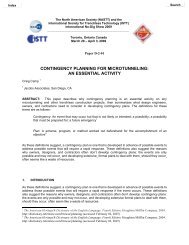
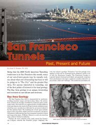
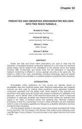
quality water to all of its customers, the SFPUC plans to construct the <strong>New</strong> <strong>Irvington</strong> <strong>Tunnel</strong> approximately parallel<br />
to the existing tunnel (Figure 1).<br />
The NIT is expected to encounter difficult and highly variable ground conditions. The rock mass is generally<br />
composed of weak, intensely fractured and sheared sedimentary rocks (mainly sandstone, siltstone, interbedded<br />
siltstone/sandstone, and shale), and also includes some sections of stronger and more massive rock. Along the<br />
proposed alignment, the tunnel will also intercept a number of fault zones with abundant clay gouge. The EIT<br />
encountered running, caving, flowing, raveling, and squeezing ground in a number of areas along the alignment.<br />
Heavy groundwater inflows were also encountered in the EIT during excavation, with reported portal flows that<br />
ranged from 500 to 2,000 gallons per minute (gpm).<br />
1
Figure 1. Location map of the <strong>New</strong> <strong>Irvington</strong> <strong>Tunnel</strong> project<br />
The concrete and steel final lining for the new tunnel will serve as the water conduit and steel pipe sections will<br />
connect to a combination of new and existing steel pipelines at each portal. The new facilities will include an<br />
overflow shaft to control the maximum hydraulic grade line in the tunnel and in the downstream pipelines. The<br />
tunnel extends about 5.6 km (3.5 mi) from a new Alameda West Portal to a new <strong>Irvington</strong> Portal. On its east<br />
(Alameda Creek) end, the new tunnel will connect to Siphons 1, 2, and 3, and a new Siphon 4. On its west<br />
(<strong>Irvington</strong>) end, the new tunnel will connect to the existing Bay Division Pipelines (BDPLs) Nos. 1, 2, 3, and 4, and<br />
a new pipeline No. 5.<br />
The NIT alignment is about 58 m (190 ft) south of the EIT from the Alameda West Portal (Sta.41+40) to Sta.<br />
154+00, for a distance of about 3,432 m (11,260 ft). From Sta. 154+00 to Sta. 183+50, the horizontal separation<br />
between the NIT and the EIT alignments increases to a maximum distance of about 204 m (670 ft). To the west of<br />
this point, near where the tunnel crosses I-680,, the separation between the NIT and EIT gradually decreases to zero<br />
at Sta. 224+00, where the NIT alignment crosses below the <strong>Irvington</strong> Portal of the EIT. The NIT extends along this<br />
bearing north of the EIT for the remaining 122 m (400 ft) of the tunnel.<br />
The NIT vertical alignment has two slopes. From the Alameda West Portal face (Sta. 41+40) to Sta. 200+00, the<br />
design slope is 0.00125. West from this point, the design slope is 0.029. The design invert elevation of the NIT<br />
varies from about El. +93 m (305 ft) at the new Alameda West Portal to about El. 62 m (202 ft) at the new <strong>Irvington</strong><br />
Portal. The NIT will be lower than the EIT for its entire length. The vertical separation between the EIT and NIT<br />
alignments ranges from about 9 m (30 ft) at the Alameda West Portal to 37 m (120 ft) at the <strong>Irvington</strong> Portal.<br />
The Alameda West Portal (AWP) provides access for constructing one of the NIT headings, connecting to the<br />
Alameda Siphon Mixing Manifold, and constructing the NIT portal access structure. In addition, the Alameda West<br />
Overflow Shaft will be constructed on the hillside above the portal. The NIT will connect to the Alameda Siphon<br />
Mixing Manifold via a connecting pipeline, intersecting the new tunnel portal pipe with a wye section.<br />
A temporary construction shaft, referred to as the Vargas Shaft, will be constructed on the east side of I-680 at<br />
Vargas Road (Figure 1). The purpose of this shaft is to provide access for the excavation of two tunnel headings in<br />
the NIT. One heading will be mined to the west towards the <strong>Irvington</strong> Portal. The other heading will be mined to the<br />
east towards the new Alameda West Portal. The shaft size will be determined by the contractor, and is anticipated to<br />
be about 10.7 to 12.2 m (35 to 40 ft) in diameter. The shaft depth will be about 36.6 m (120 ft).<br />
2
The <strong>Irvington</strong> Portal provides access for construction of an eastward tunnel heading and to connect the tunnel with<br />
the Bay Division Pipelines. The <strong>Irvington</strong> Portal is located at Sta. 228+00, where the tunnel has an invert elevation<br />
of about El. 62 m (202 ft). The <strong>Irvington</strong> Portal is adjacent to private homes, and most work will be limited to<br />
daytime hours in order to minimize impacts. The maximum length of tunnel that can be driven from this portal will<br />
be limited to 168 m (550 ft) to reduce the amount of truck traffic in the area.<br />
GEOLOGIC CONDITIONS<br />
The ground surface above the tunnel generally consists of rolling hills covered with grass, brush, and trees. A<br />
number of privately owned parcels will be crossed by the tunnel alignment. These parcels have domestic water<br />
supply wells, livestock and irrigation wells, and natural springs that indicate the local availability of groundwater in<br />
the vicinity of the tunnel alignment.<br />
Ground cover above the tunnel varies along the alignment, ranging from about 6.1 to 228.6 m (20 to 750 ft). Ground<br />
elevations along the tunnel alignment vary from about El. 72 m (235 ft) at the <strong>Irvington</strong> Portal to about El. 320 m<br />
(1,050 ft) at the high point in the central portion of the alignment.<br />
The rocks along the NIT alignment consist of marine sedimentary sandstone, shale, siltstone, and chert ranging in<br />
age from Miocene to Cretaceous (5 to 144 million years old). Younger Quaternary-period deposits include alluvium<br />
and colluvium, which are present at the Alameda West Portal, Sheridan Valley, in the vicinity of I-680, and at the<br />
<strong>Irvington</strong> Portal. Geologic units crossed by the tunnel alignment include (in order of increasing age) unconsolidated<br />
Quaternary-period deposits and artificial fill (Qoa, Qc, af), Briones Formation (Tbr), Tice Shale Formation (Tt),<br />
Oursan Sandstone Formation (To), Claremont Formation (Claremont Formation Chert and Shale Member [Tcc] and<br />
Sandstone Member [Tcs]), and the Cretaceous Sandstone and Shale (Ks). The geologic unit names are consistent<br />
with USGS geologic maps, but in some cases, the names do not match the bedrock lithology present within the<br />
tunnel. For example, the Ks unit includes extensive siltstone and sandstone but relatively little shale.<br />
The NIT lies in the western ridges of the Diablo Range. This range has been subjected to significant faulting and<br />
folding, which has fractured and sheared the rocks along the tunnel alignment. Regional tectonic compression has<br />
uplifted the range and created folds that form at least one anticline and one large syncline (Niles Syncline) in the site<br />
area.<br />
Fault-bounded blocks are formed by four mapped faults that cross the tunnel alignment: the Pirate Creek, Sheridan<br />
Creek, Unnamed, and Mill Creek faults. At least three additional faults and shear zones without surface expressions<br />
were observed during the EIT construction. Strata within the fault-bounded blocks tend to dip to the southwest<br />
between the AWP and Sheridan Creek fault, and are folded into a syncline between the Sheridan Creek fault and the<br />
Unnamed fault east of I-680. Strata between the Unnamed fault and the Mill Creek fault are folded to form a<br />
northwest-trending anticline. West of the Mill Creek fault, the strata dip to the northeast. Bedding dip inclinations<br />
range from moderate to vertical within these folds and are commonly steepest in the vicinity of faults. The largest<br />
fold feature is the Niles Syncline, with a near vertical axial plane mapped at approximately Sta. 140+50. The<br />
Claremont, Tice, and Briones formations will be encountered two to three times along the alignment because of the<br />
folding involved with the regional structure.<br />
An extensive program of geotechnical investigation was completed during design. The investigation objectives were<br />
to characterize the soil and rock conditions, lithologic and fault contacts, and groundwater conditions along the<br />
tunnel alignment. The investigations included geologic mapping, exploratory borings, downhole testing and logging,<br />
surface geophysics, and laboratory testing.<br />
Because of the complexity of the conditions encountered, the subsurface investigations program ultimately grew to<br />
include 38 exploratory borings, ranging from 15.2 to over 228.6 m deep (50 to over 750 ft). The total length drilled<br />
was over 2,652 m (8,700 ft), nearly double the originally anticipated footage. Twenty-five of the borings were<br />
drilled vertically, and 13 were inclined. Standpipe piezometers and/or vibrating wire piezometers were installed in<br />
28 borings. The drilling was primarily performed using LF-70 and CS-1000 skid-mounted rotary rigs equipped with<br />
HQ-3 wireline core barrels. Sonic drilling equipment was also used in one area in an effort to improve sample<br />
recovery.<br />
3
Water pressure (packer) testing was performed in a total of 17 core borings. Downhole geophysical surveys,<br />
including caliper logging and televiewer logging, were performed in 15 borings. Seismic velocity surveys (OYO<br />
suspension) were performed in 8 borings. The televiewer logging results were used to characterize the in situ<br />
frequency and orientation of rock discontinuities, fractures, bedding, and shear zones.<br />
Surface seismic refraction surveys were completed at each portal area to assist in characterizing the overburden<br />
depths and bedrock properties. Surface wave geophysical surveys were performed to investigate the deeper<br />
overburden in the Vargas Road area. Aquifer pumping tests were carried out at the Vargas Road and the Sheridan<br />
Valley sites to investigate the hydrogeologic formation properties.<br />
Laboratory testing was performed on selected rock core samples. The tests included uniaxial compressive strength,<br />
point load strength, indirect (Brazilian) tensile strength, punch-penetration, slake durability, Cerchar abrasivity<br />
index, thin-section petrographic analysis, specific gravity, modulus and uniaxial compression, triaxial compression,<br />
and multistage direct shear tests on joint samples.<br />
GROUND CHARACTERIZATION<br />
An extensive program of geotechnical investigations was completed as part of the design process (URS 2009).<br />
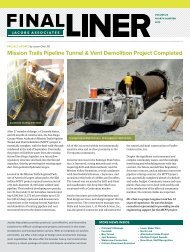
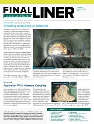
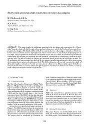
Based on the results, the tunnel alignment has been divided into eight reaches. The reach boundaries were<br />
established at the estimated contacts between the geologic formations (Figure 2). The locations of the geologic<br />
contacts were estimated based on the available geologic data, interpolation between borings, evaluation of surface<br />
geologic mapping data, and correlation with the EIT construction records. The reaches are shown in Table 1.<br />
Table 1: Summary of the tunnel reaches<br />
Reach (Stationing) Length, m (ft) Geologic Formations Anticipated Fault<br />
Zones<br />
1 (Sta. 41+40 to Sta. 75+90) 1,052 m (3,450 ft) Cretaceous Sandstone and Shale<br />
(Ks)<br />
None<br />
2 (Sta.75+90 to Sta. 86+50) 323 m (1,060 ft) Claremont Chert and Shale<br />
(Tcc); Oursan Sandstone (To)<br />
3 (Sta. 86+50 to Sta. 104+00) 533 m (1,750 ft) Tice Shale (Tt) Fault A<br />
4 (Sta. 104+00 to Sta. 158+50) 1,661 m (5,450 ft) Briones Formation (Tbr) Fault B<br />
Pirate Creek Fault;<br />
Sheridan Creek Fault<br />
5 (Sta. 158+50 to Sta. 173+00) 442 m (1,450 ft) Tice Shale (Tt); Claremont Chert Unnamed Fault<br />
and Shale (Tcc)<br />
6 (Sta. 173+00 to Sta. 190+50) 533 m (1,750 ft) Claremont Sandstone (Tcs) None<br />
7 (Sta.190+50 to Sta. 198+70) 250 m (820 ft) Claremont Chert and Shale (Tcc) Fault C; Mill Creek<br />
Fault<br />
8 (Sta. 198+70 to Sta. 228+00) 893 m (2,930 ft) Briones Formation (Tbr) None<br />
Ground conditions that will be encountered along the tunnel alignment have been divided into four ground classes to<br />
aid in the selection of tunnel excavation and support methods. Ground classes were defined based on the physical<br />
characteristics of the ground and its anticipated behavior during the tunnel excavation. The ground assigned to a<br />
particular class is expected to perform similarly in the tunnel excavation, and to require similar support methods.<br />
Each ground class will be encountered multiple times throughout the tunnel in all tunnel reaches. The ground class<br />
definitions, predominant ground behaviors, and key characteristics associated with each ground class are described<br />
in Table 2. Potentially unstable ground conditions will be encountered throughout the tunnel, including but not<br />
limited to, raveling/caving, squeezing, swelling, running, and flowing conditions. The sheared nature of the rock<br />
mass, weak rocks, abundant clay infilling materials, intensely fractured rock mass, and high groundwater levels all<br />
will contribute to the instability of the tunnel excavation if not properly controlled. Control of groundwater inflows<br />
into the tunnel by pre-drainage and/or pre-excavation grouting will be necessary to minimize adverse effects on<br />
unstable ground and excavation progress.<br />
4
Figure 2. Generalized geologic profile of the <strong>New</strong> <strong>Irvington</strong> <strong>Tunnel</strong> project<br />
5
Table 2: Definitions of ground classes<br />
Ground Class and<br />
Definitions<br />
I: Massive to<br />
Moderately Fractured<br />
Rock<br />
II: Highly Fractured<br />
Rock<br />
III Intensely Fractured<br />
Rock<br />
IV: Heavily<br />
Sheared/Faulted Rock<br />
with Clay<br />
Gouge/Infilling<br />
Materials<br />
Typical Rock Characteristics<br />
Sandstone, siltstone, and interbedded<br />
siltstone/sandstone; weak to strong rock;<br />
slightly weathered to fresh<br />
Sandstone, siltstone, interbedded<br />
siltstone/sandstone, and shale; weak to<br />
moderately strong rock; highly to<br />
slightly weathered<br />
Sandstone, siltstone, interbedded<br />
siltstone/sandstone, and shale; thinly<br />
bedded to laminated rock structure; very<br />
weak to moderately strong rock, may be<br />
friable, poorly cemented; highly to<br />
slightly weathered/altered<br />
Heavily sheared rock including fault<br />
gouge, shattered rock, all with abundant<br />
clay; extremely weak to very weak rock;<br />
moderately to completely<br />
weathered/altered<br />
Typical Discontinuity<br />
Characteristics<br />
Very rough to rough; fresh to<br />
slightly weathered surfaces<br />
Rough, smooth, or slickensided<br />
surfaces or bedding planes;<br />
moderately to highly<br />
weathered/altered surfaces with<br />
infillings of clay and/or sand<br />
Smooth, slickensided surfaces;<br />
highly weathered/altered with<br />
occasional moderately wide<br />
clay/sand-filled joints, shears,<br />
and shear zones<br />
Slickensided surfaces; highly<br />
weathered/altered with wide<br />
clay-filled joints, shears, and<br />
fault/shear zones<br />
Ground<br />
Behavior<br />
Structurally<br />
controlled block<br />
instability; spalling<br />
Slow raveling; fast<br />
raveling where<br />
flowing<br />
groundwater is<br />
encountered<br />
Fast<br />
raveling/caving;<br />
potentially flowing<br />
ground<br />
Squeezing;<br />
swelling; caving;<br />
fast raveling<br />
The anticipated ground conditions along the tunnel were estimated based on evaluation of the geologic and<br />
geotechnical data collected for this project, along with review and correlation of the available EIT construction<br />
records. Rock mass quality evaluations were performed utilizing the Rock Quality <strong>Design</strong>ation (RQD) (Deere and<br />
Deere 1988) and the Rock Mass Rating (RMR) system (Bieniawski 1988).<br />
During the review process, we discovered that the EIT construction records contain some inconsistencies in their<br />
descriptions of the ground conditions and lithology encountered in the tunnel. In addition, the records provide no<br />
definitions of the descriptive or geologic terms used, and it appears that some of the terms used differ from current<br />
practice. Therefore, the EIT records were interpreted based on our understanding of site geology and the<br />
construction methods employed at the time of construction for each reach of the NIT. As an example, “running<br />
ground” identified in the EIT in areas of high groundwater inflow was concluded to be “flowing ground” in current<br />
tunneling terminology.<br />
Significant shearing and many shear zones were observed in the geotechnical investigation borings completed for<br />
the NIT. Similar conditions are reported in the EIT construction records. The estimated amount of sheared/faulted<br />
rock in the NIT based on the EIT records ranges up to 90 percent over some reaches (in terms of the tunnel length<br />
impacted by sheared/faulted rock).<br />
TUNNEL EXCAVATION AND SUPPORT<br />
The NIT will be constructed in variable ground conditions, ranging from strong, massive rock to very weak and<br />
intensely fractured and sheared rock including fault gouge. The tunnel will encounter high groundwater inflows and<br />
difficult ground conditions including raveling, running, flowing, caving, and squeezing ground. Conventional<br />
tunneling methods, including the use of roadheaders, drill-and-blast techniques, and hydraulic excavators, are<br />
expected to be adaptable to the anticipated wide range of ground conditions, including running, caving, flowing,<br />
raveling, and squeezing ground in a number of areas along the alignment.<br />
The potential for use of a tunnel boring machine (TBM) was evaluated and concluded to be unacceptable for several<br />
reasons. Given the anticipated highly variable and difficult ground conditions, high groundwater inflows, and high<br />
groundwater pressures present along portions of the alignment, the use of a TBM, especially a machine of the size<br />
required for this project, was concluded to present excessive risks in terms of the cost and schedule impacts to the<br />
project. Use of a TBM would also restrict access to the tunnel face and would hamper the use of ground<br />
improvement techniques needed on this project. In addition, the seismic reliability goal of the project requires a steel<br />
6
pipe lining across zones of potential sympathetic fault offset. The use of a TBM (with a continuous full-perimeter<br />
lining) would restrict the face inspection and mapping needed to detect and delineate the lengths and locations of<br />
these zones.<br />
The tunnel excavation methods, initial support systems, and groundwater control measures for the tunnel will be<br />
determined by the contractor. The EIT was mainly excavated using drill-and-blast methods, although “hand spades”<br />
were used in two sections of the tunnel to excavate the Claremont Formation in the vicinity of Reach 5. Several<br />
excavation methods could be applied to the NIT, including roadheaders, drill-and-blast methods, and mechanical<br />
excavation. The selected approach will depend mainly on economics, equipment availability (for a tunnel of this<br />
size), and the skills and experience of the contractor’s crew. Key geotechnical issues include rock types, strength<br />
and degree of fracturing of the rock mass, and groundwater conditions.<br />
Roadheaders are expected to be capable of excavating most of the tunnel reaches where the rock mass is moderately<br />
weak or weaker and highly fractured. The performance of a roadheader will depend on the machine size and weight,<br />
and the rock strength (UCS), fracture spacing, and abrasivity.<br />
Drill-and-blast excavation methods were used extensively for the EIT and are applicable to most of the NIT, the<br />
exception being zones of intensely fractured, sheared rock with significant clay content and the fault zones. The<br />
maximum round lengths for blasting will depend on face stability, rock mass quality, initial support requirements,<br />
and other factors. Wherever blasting is used, appropriate blast designs and vibration and noise monitoring will be<br />
required to control and minimize potential impacts of blasting on the existing tunnel, existing pipeline facilities, and<br />
residences adjacent to the portals and above the tunnel alignment.<br />
The NIT will have a two-pass support system consisting of an initial support system and a final lining. The initial<br />
support requirements will vary along the tunnel due to the range of ground conditions that will be encountered<br />
during construction.<br />
Presupport using spiling and/or forepoling will be required to control raveling, caving, and crown instability,<br />
primarily in tunnel reaches with Ground Class III and IV conditions. Presupport may also be required to prevent<br />
structurally controlled block instability, expected primarily in Ground Classes I and II. Face support in conjunction<br />
with pre-support is expected to be required to control block instability, overbreak, raveling, running/flowing, slaking<br />
and caving behaviors at the tunnel face in Ground Classes II, III, and IV.<br />
GROUNDWATER CONTROL<br />
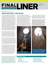
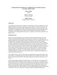
The anticipated groundwater levels above the tunnel crown range from zero to 112.8 m (370 ft). Groundwater<br />
inflows are anticipated throughout a significant portion of the tunnel. The heaviest flows will occur where the<br />
ground is highly fractured and where fault and shear zones are encountered. Estimates of the maximum potential<br />
groundwater flush flows and sustained flows were made for each of the NIT reaches. The estimates were based on<br />
the results of the groundwater modeling for present-day conditions and on interpretation of the EIT construction<br />
records (Figure 3).<br />
Implementation of effective groundwater control measures will be required to limit uncontrolled inflows into the<br />
tunnel and to reduce the impact of inflows on tunnel construction. Additional inflow control measures will be<br />
required where needed to protect groundwater wells and resources, as directed by SFPUC.<br />
Predrainage of the rock mass ahead of the face is expected to be feasible from within the tunnel in many areas. At<br />
selected locations, predrainage from the ground surface is also feasible. The contractor must implement preexcavation<br />
grouting, predrainage, and/or a combination of both measures, as necessary, to reduce sustained<br />
groundwater inflows to within workable limits. Predrainage from within the tunnel is considered feasible when the<br />
probe holes indicate the potential for significant groundwater inflows into the tunnel. Predrainage has the following<br />
objectives:<br />
• Reduce high groundwater inflow potential,<br />
• Improve the efficiency of the pre-excavation grouting, and, if necessary,<br />
• Improve ground behavior.<br />
7
Figure 3. EIT flush flows interpreted from portal flow records and shown based on the NIT stationing and<br />
reaches<br />
Drain holes drilled ahead of the tunnel face can reduce the groundwater head and aid in the control of heading<br />
inflows. Depending on the fracture openings, fracture spacings, and storativity of the rock mass, the effectiveness of<br />
drainage will vary. Typically, drainage would be done ahead of the advancing face to improve the ground behavior<br />
at the tunnel walls, roof, and face.<br />
Predrainage from the ground surface using dewatering wells is planned to supplement dewatering from within the<br />
tunnel in two areas along the alignment: Sheridan Valley and the Vargas Road/I-680 corridor. At each site, the<br />
contractor will be required to design and install a dewatering system to lower the groundwater table in advance of<br />
tunnel excavation, in areas where problematic ground conditions and/or high water inflows are expected.<br />
Pre-excavation grouting requires the injection of grout to fill open fractures in the rock mass. Typical pre-excavation<br />
grouting will not penetrate intact rock or joint infillings with low porosity. In zones of completely weathered/altered<br />
rock, clay-filled shears and clay fault gouge, or intensely fractured rock, grout penetration is expected to be limited<br />
because of low hydraulic conductivity, so the effectiveness of pre-excavation grouting for groundwater control and<br />
ground improvement will also be limited. In areas where the rock exhibits high hydraulic conductivity, treatment of<br />
the fractured rock mass through grouting is expected to be more effective. The performance objectives for preexcavation<br />
grouting and drainage are as follows:<br />
• Limit the groundwater inflows at the tunnel face to a rate compatible with the selected tunnel construction<br />
means and methods.<br />
• Mitigate adverse ground behavior caused by heavy groundwater inflows as necessary to allow adequate<br />
installation of initial support measures.<br />
The contractor’s drilling, casing, and grouting equipment and methods must be capable of staged grouting in<br />
unstable rock formations. The probe and grout holes are expected to encounter hole stability problems in weak rock<br />
8
that includes highly to intensely fractured rock and clayey shear and fault zones. Due to uncertainties associated<br />
with the characteristics of groundwater flows in a fractured rock mass, the required probe and verification holes are<br />
not expected to detect all potential inflows. The actual inflows encountered at the tunnel face may vary substantially<br />
from estimates based on probe hole flows. The contractor must be prepared to adjust pre-excavation grouting and<br />
drainage techniques, criteria, and procedures during construction to accommodate the expected rapidly varying<br />
ground conditions.<br />
Inflows into the tunnel may negatively impact existing water wells and nearby springs. If monitoring data indicate<br />
unacceptable impacts are occurring, the owner may direct the contractor to implement additional control measures.<br />
Feasible additional measures include additional pre-excavation grouting, the installation of a built-up shotcrete<br />
lining for controlling water inflows in conjunction with controlling ground stability, and other effective measures<br />
proposed by the contractor.<br />
SEISMIC DESIGN<br />
The NIT is located in a seismically active region of California, dominated by the San Andreas fault system. The<br />
nearby Hayward fault on the west and the Calaveras fault on the east are capable of generating large (Magnitude<br />
7.0) earthquakes. In addition to these two faults, numerous other, active faults are located within 48.3 km (30 mi)<br />
of the tunnel site. However, the tunnel alignment does not cross any faults that have been zoned as Alquist-Priolo<br />
Earthquake Fault Zones by the state of California. The Alquist-Priolo Earthquake Fault Zones are defined based on<br />
evidence of Holocene surface rupture (i.e., within the last 11,000 years). Surface mapping completed as part of the<br />
geotechnical investigations (URS 2009) found no evidence for Holocene surface rupture on any of the mapped faults<br />
crossing the tunnel alignment.<br />
According to the SFPUC’s General Seismic <strong>Design</strong> Requirements (SFPUC 2006), the NIT is specified as a Seismic<br />
Performance Class III facility. The design earthquake for the Seismic Performance Class III facilities has a 5 percent<br />
probability of exceedance in 50 years (975-year approximate return period). The SFPUC’s objective for seismic<br />
performance of the tunnel is to deliver winter day demand of water within 24 hours of a major earthquake (SFPUC,<br />
2006). In order for this objective to be achieved, catastrophic damage to the facilities during the design earthquake<br />
must be avoided. The seismic design parameters for the NIT were developed based on a seismic hazard and ground<br />
response analysis (URS 2007).<br />
Depending on distance from the active faults, the estimated peak ground accelerations (PGA) along the tunnel<br />
alignment for the design earthquake vary from 0.85 g to 1.02 g at the ground surface level, and from 0.45 g to 0.58 g<br />
at the tunnel level. The peak ground velocities (PGV) range from 148 to 160 cm/s (58.3 to 62.9 in./sec) at the ground<br />
surface level, and from 47 to 58 cm/sec (18.5 to 22.8 in./sec) at the tunnel level.<br />
Although the NIT alignment does not cross any seismically active faults, up to 150 mm (6 in.) of sympathetic<br />
displacement over a width of 1.5 m (5 ft) is considered possible on any or all of the four mapped secondary faults<br />
(Pirate Creek, Sheridan Creek, Unnamed, and Mill Creek faults). Sympathetic displacement could occur in response<br />
to a significant earthquake event on either the Hayward or Calaveras fault (WLA 2007).<br />
In order to minimize the potential impact of sympathetic displacements on the NIT final lining, the design included<br />
steel pipe final lining in areas where the NIT crosses the four mapped fault zones. The steel pipe is more ductile than<br />
concrete and can tolerate much higher deformations or strains without rupture or collapse. However, because the<br />
design displacement occurs over a very short length, high shear strains in the steel pipe are expected. To investigate<br />
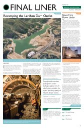
the effects of potential fault offset on the steel pipe final lining and finalize the pipe design, numerical analyses were<br />
performed using the three-dimensional finite-difference program FLAC3D (Fast Lagrangian Analysis of Continua in<br />
3 Dimensions) Version 3.0 (Itasca, 2005). The FLAC3D analyses were used to calculate deformations and stresses<br />
induced in the steel pipe final lining by the design. A typical model used in the FLAC3D analyses is illustrated in<br />
Figure 4. In the analyses, two blocks of rock, one on either side of a 2.7-m (9-ft) wide fault zone were offset in the<br />
opposite directions along the fault plane. The resulting total relative displacement between these two blocks of rock<br />
masses was equal to the design displacement of 150 mm (6 in.) considered.<br />
9
Figure 4. Typical FLAC3D model for fault offset analysis<br />
Key parameters were varied in the analysis to optimize the design and assess the impact of potential uncertainties.<br />
The key parameters include the stiffness of backfill concrete, wall thickness of steel pipe, magnitude of fault offset,<br />
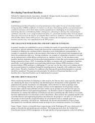
and deformation moduli of rock mass and fault zone. Figure 5 shows a typical deformed shape (magnified by 20<br />
times) of the tunnel steel pipe final lining following a 150-mm (6-in.) fault offset. Results of the analyses indicated<br />
that the maximum stress in the steel pipe increases with stiffness of the backfill concrete. In order to control the<br />
maximum stresses in the steel pipe to within tolerable limits, use of a special low-density backfill concrete to fill the<br />
annular space between the initial support and the steel pipe will be required. This special backfill will consist of<br />
cellular concrete with an unconfined compressive strength between 1.37 and 2.07 MPa (200 and 300 psi).<br />
PORTAL EXCAVATION AND SUPPORT<br />
Development of the portals for tunnel construction and installation of pipeline connections will be a critical element<br />
of the project. The preparatory work will include access development, installation of erosion and sedimentation<br />
control measures, and protection of existing SFPUC pipelines and portal structures.<br />
The two portal excavations will require both soil and rock excavation techniques. Rock near the portals is expected<br />
to be highly to intensely fractured, with an average fracture spacing of less than one foot. The use of appropriately<br />
sized excavating and earth-moving equipment will be suitable for most of the portal excavations. Drill-and-blast<br />
methods or impact hammer methods will be required to break up harder, more massive rock in localized areas.<br />
However, such excavation methods and related construction activities may disturb nearby residents and affect the<br />
stability of adjacent pipelines, slopes and shoring systems. The project includes very tight noise and vibration<br />
criteria and required measures to reduce and mitigate potential impacts.<br />
10
Figure 5. Contours of shear stresses and deformed shape of the steel pipe lining caused by fault sympathetic<br />
displacement<br />
To achieve slope stability, all portal excavation cut slopes will require temporary support measures, such as fully<br />
grouted soil nails, shotcrete, rock dowels, rock bolts, and/or other measures as appropriate for the subsurface<br />
conditions encountered. In addition, to achieve a stable tunnel excavation at the portal, reinforcement of the rock<br />
mass above the tunnel crown will be required, by installation of portal spiles or forepoling before starting the tunnel.<br />
Typical minimum required ground support measures for the portal excavation sidewalls are shown in Figure 6.<br />
PROJECT SCHEDULE<br />
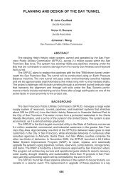
The design of the project was completed in December 2009 and advertised for bidding in January 2010. Bid opening<br />
was March 2010. Notice to proceed is anticipated in June 2010. The project has a 42-month construction schedule<br />
and completion is scheduled for November 2013.<br />
CONCLUSION<br />
The first tunnel was built with very little advanced information. The miners in 1928 drove the tunnel blindly, with<br />
no advanced exploration, no probe hole drilling, limited ability to grout, and used timber sets. Information collected<br />
during construction of the existing tunnel has been valuable in the design of the new <strong>Irvington</strong> <strong>Tunnel</strong> project to help<br />
limit some of the challenges to be faced. That information combined with today’s tunneling equipment, technology,<br />
materials, increased exploration, advanced planning, and the ability to probe, drain, grout and dewater from the<br />
surface, should allow the <strong>New</strong> <strong>Irvington</strong> <strong>Tunnel</strong> to be completed with much fewer construction problems and much<br />
greater ability to survive the next major earthquake in the area.<br />
11
Figure 6. Typical portal excavation support<br />
REFERENCES<br />
Bieniawski, Z. T. 1988. The Rock Mass Rating (RMR) system (geomechanics classification) in engineering<br />
practice. In Rock Mass Classification Systems for Engineering Purposes. Edited by L. Kirkaldie, 17–101.<br />
Philadelphia, Penn.: American Society for Testing of Materials, ASTM STP 984.<br />
Deere, D.U., and Deere, D.W. 1988. The Rock Quality <strong>Design</strong>ation (RQD) index in practice. In: Rock classification<br />
Systems for Engineering Purposes, L. Kirkaldie, ed., 91–101. Philadelphia, Penn.: American Society for Testing<br />
of Materials, ASTM STP 984.<br />
Itasca. 2005. Fast Lagrangian Analysis of Continua in 3 Dimensions (FLAC3D), Version 3.0, Itasca Consulting<br />
Group, Minneapolis, Minnesota.<br />
SFPUC (San Francisco Public Utilities Commission). 2006. General Seismic Requirements for <strong>Design</strong> of <strong>New</strong><br />
Facilities and Upgrade of Existing Facilities.<br />
URS (URS Corporation). 2007. Seismic Hazard Analysis, <strong>New</strong> <strong>Irvington</strong> <strong>Tunnel</strong> Project. Draft Technical<br />
Memorandum 6-06, prepared for the San Francisco Public Utilities Commission, June.<br />
URS. 2009. Geotechnical Data Report, <strong>New</strong> <strong>Irvington</strong> <strong>Tunnel</strong> Project. Final Report prepared for the San Francisco<br />
Public Utilities Commission, November.<br />
URS and <strong>Jacobs</strong> <strong>Associates</strong>. 2009. Geotechnical Baseline Report, <strong>New</strong> <strong>Irvington</strong> <strong>Tunnel</strong> Project. Final Report prepared<br />
for the San Francisco Public Utilities Commission, November.<br />
WLA (William Lettis & <strong>Associates</strong>, Inc.). 2007. Geologic Investigation of Possible Deformation Expected on<br />
Secondary Faults Along the <strong>New</strong> <strong>Irvington</strong> <strong>Tunnel</strong> Corridor, Alameda County, California. Technical<br />
Memorandum prepared for URS Corporation, October 26.<br />
12