INTELLIGENT FIRE ALARM CONTROL PANELS MR ... - Secutron
INTELLIGENT FIRE ALARM CONTROL PANELS MR ... - Secutron
INTELLIGENT FIRE ALARM CONTROL PANELS MR ... - Secutron

Create successful ePaper yourself
Turn your PDF publications into a flip-book with our unique Google optimized e-Paper software.
<strong>INTELLIGENT</strong><br />
<strong>FIRE</strong> <strong>ALARM</strong> <strong>CONTROL</strong> <strong>PANELS</strong><br />
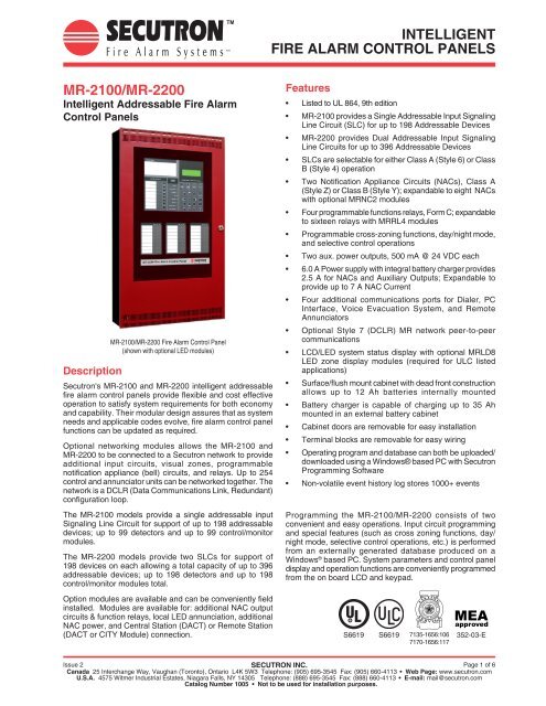
<strong>MR</strong>-2100/<strong>MR</strong>-2200<br />
Intelligent Addressable Fire Alarm<br />
Control Panels<br />
Description<br />
<strong>MR</strong>-2100/<strong>MR</strong>-2200 Fire Alarm Control Panel<br />
(shown with optional LED modules)<br />
<strong>Secutron</strong>'s <strong>MR</strong>-2100 and <strong>MR</strong>-2200 intelligent addressable<br />
fire alarm control panels provide flexible and cost effective<br />
operation to satisfy system requirements for both economy<br />
and capability. Their modular design assures that as system<br />
needs and applicable codes evolve, fire alarm control panel<br />
functions can be updated as required.<br />
Optional networking modules allows the <strong>MR</strong>-2100 and<br />
<strong>MR</strong>-2200 to be connected to a <strong>Secutron</strong> network to provide<br />
additional input circuits, visual zones, programmable<br />
notification appliance (bell) circuits, and relays. Up to 254<br />
control and annunciator units can be networked together. The<br />
network is a DCLR (Data Communications Link, Redundant)<br />
configuration loop.<br />
The <strong>MR</strong>-2100 models provide a single addressable input<br />
Signaling Line Circuit for support of up to 198 addressable<br />
devices; up to 99 detectors and up to 99 control/monitor<br />
modules.<br />
The <strong>MR</strong>-2200 models provide two SLCs for support of<br />
198 devices on each allowing a total capacity of up to 396<br />
addressable devices; up to 198 detectors and up to 198<br />
control/monitor modules total.<br />
Option modules are available and can be conveniently field<br />
installed. Modules are available for: additional NAC output<br />
circuits & function relays, local LED annunciation, additional<br />
NAC power, and Central Station (DACT) or Remote Station<br />
(DACT or CITY Module) connection.<br />
Features<br />
•<br />
Listed to UL 864, 9th edition<br />
• <strong>MR</strong>-2100 provides a Single Addressable Input Signaling<br />
Line Circuit (SLC) for up to 198 Addressable Devices<br />
• <strong>MR</strong>-2200 provides Dual Addressable Input Signaling<br />
Line Circuits for up to 396 Addressable Devices<br />
• SLCs are selectable for either Class A (Style 6) or Class<br />
B (Style 4) operation<br />
• Two Notification Appliance Circuits (NACs), Class A<br />
(Style Z) or Class B (Style Y); expandable to eight NACs<br />
with optional <strong>MR</strong>NC2 modules<br />
• Four programmable functions relays, Form C; expandable<br />
to sixteen relays with <strong>MR</strong>RL4 modules<br />
• Programmable cross-zoning functions, day/night mode,<br />
and selective control operations<br />
•<br />
Two aux. power outputs, 500 mA @ 24 VDC each<br />
• 6.0 A Power supply with integral battery charger provides<br />
2.5 A for NACs and Auxiliary Outputs; Expandable to<br />
provide up to 7 A NAC Current<br />
• Four additional communications ports for Dialer, PC<br />
Interface, Voice Evacuation System, and Remote<br />
Annunciators<br />
• Optional Style 7 (DCLR) <strong>MR</strong> network peer-to-peer<br />
communications<br />
• LCD/LED system status display with optional <strong>MR</strong>LD8<br />
LED zone display modules (required for ULC listed<br />
applications)<br />
• Surface/flush mount cabinet with dead front construction<br />
allows up to 12 Ah batteries internally mounted<br />
• Battery charger is capable of charging up to 35 Ah<br />
mounted in an external battery cabinet<br />
•<br />
•<br />
Cabinet doors are removable for easy installation<br />
Terminal blocks are removable for easy wiring<br />
• Operating program and database can both be uploaded/<br />
downloaded using a Windows® based PC with <strong>Secutron</strong><br />
Programming Software<br />
•<br />
Non-volatile event history log stores 1000+ events<br />
Programming the <strong>MR</strong>-2100/<strong>MR</strong>-2200 consists of two<br />
convenient and easy operations. Input circuit programming<br />
and special features (such as cross zoning functions, day/<br />
night mode, selective control operations, etc.) is performed<br />
from an externally generated database produced on a<br />
Windows ® based PC. System parameters and control panel<br />
display and operation functions are conveniently programmed<br />
from the on board LCD and keypad.<br />
S6619<br />
S6619<br />
7135-1656:106<br />
7170-1656:117<br />
MEA<br />
approved<br />
352-03-E<br />
Issue 2 SECUTRON INC.<br />
Page 1 of 6<br />
Canada 25 Interchange Way, Vaughan (Toronto), Ontario L4K 5W3 Telephone: (905) 695-3545 Fax: (905) 660-4113 • Web Page: www.secutron.com<br />
U.S.A. 4575 Witmer Industrial Estates, Niagara Falls, NY 14305 Telephone: (888) 695-3545 Fax: (888) 660-4113 • E-mail: mail@secutron.com<br />
Catalog Number 1005 • Not to be used for installation purposes.
Main Control Unit<br />
System controls consist of eight system switches, an LCD<br />
readout, and display entry switches. The display entry<br />
keypad is used for technical functions, system/detector<br />
maintenance, history recall, device and circuit disarming,<br />
and for manual operation of addressable output modules,<br />
relay modules, and notification appliance (bell) circuits.<br />
Operator Keys<br />
There are eight operator keys. In the figure below, the<br />
keys are located on the lower left and are labeled “System<br />
Controls.” The LEDs associated with these keys are used to<br />
display function status. The top three keys are pre assigned<br />
and are: Acknowledge, Signal Silence, and System Reset.<br />
The bottom five keys are user-assignable, selected for the<br />
following functions: Lamp Test, Relay Disconnect, Test<br />
Mode, Signal Disconnect, Common Disconnect, General<br />
Alarm, Selectable Switch Function On, Switch Function Off,<br />
or Manual Restart.<br />
The panel local sounder will beep once when a valid key is<br />
pressed and beep three times if an invalid or unavailable key<br />
is pressed. Key presses are recorded in the history log.<br />
Intelligent Addressable Input Circuits<br />
Up to 99 intelligent addressable detectors and up to 99<br />
addressable control/monitoring modules may be connected<br />
per SLC for a total of 198 addressable devices. <strong>MR</strong>-2100<br />
models provide a single SLC output, <strong>MR</strong>-2200 models<br />
provide dual SLCs.<br />
Addressable monitoring modules can be programmed for<br />
alarm or supervisory functions. Control modules are available<br />
for dry contact or supervised output functions.<br />
NAC Outputs<br />
Standard are two NACs rated 2 A maximum. NAC output<br />
voltage is a nominal 24 VDC, full wave rectified. NAC<br />
expansion can be up to eight NACs by using <strong>MR</strong>NC2 NAC<br />
expander modules.<br />
Auxiliary Outputs<br />
Two auxiliary power outputs are provided, each rated for 500<br />
mA at a nominal 24 VDC, filtered and regulated.<br />
INSTRUCTIONS:<br />
SYSTEM <strong>CONTROL</strong>S<br />
Acknowledge<br />
Signal Silence<br />
System Reset<br />
User Assigned<br />
<strong>ALARM</strong><br />
SUPERVISORY<br />
TROUBLE<br />
AC<br />
MONITOR<br />
BYPASS<br />
GROUND FAULT<br />
NAC TROUBLE<br />
<strong>MR</strong>-2100/2200 Main Control Panel<br />
SYSTEM DISPLAY AND PROGRAMMING<br />
<strong>ALARM</strong> SUPERV TROUBLE MONITOR<br />
1 2 3<br />
4 5 6<br />
7 8 9<br />
Display Information<br />
The Main Control Panel LCD readout is backlighted and<br />
displays 4 lines with 20 characters per line. With AC power<br />
present, the LCD backlighting turns off automatically within<br />
5 minutes if no activity occurs. During AC power failure, the<br />
backlighting will turn off within 30 seconds without activity.<br />
During normal conditions the display is the main menu<br />
which includes the date and a 24 hour clock. During alarm<br />
conditions, the first or last (selectable) events of highest<br />
priority will be displayed instead of the main menu. A<br />
status summary screen lists the number of active alarm,<br />
supervisory, or trouble events indicating “SYSTEM OFF<br />
NORMAL.”<br />
ENTER<br />
CLEAR<br />
HOME<br />
LAMP<br />
TEST<br />
Function Relays<br />
The panel comes with four programmable Form C function<br />
relays rated 2 A @ 30 VDC resistive. Total function relays<br />
can be expanded to 16 by using <strong>MR</strong>RL4 relay expander<br />
modules. Relays can be programmed as Common Alarm,<br />
Common Trouble, Common Supervisory, or general purpose<br />
functions.<br />
Power Supply and Expansion Transformer<br />
Each <strong>MR</strong>-2100 / <strong>MR</strong>-2200 fire alarm control panel is shipped<br />
with a 120 VAC / 240 VAC transformer. Total NAC power<br />
can be increased by adding a second transformer, <strong>MR</strong>-XPS.<br />
The standard power supply provides 2.5 A @ 24 VDC (full<br />
wave rectified, unfiltered) for the total of NAC and Auxiliary<br />
power output. With the addition of an optional transformer,<br />
the total NAC and Auxiliary power output is increased to 8 A<br />
with up to 7 A available for NACs.<br />
Enclosure Details<br />
The enclosure includes the mounting box, outer door, dead<br />
front door, and hardware plate. It can be flush or surface<br />
mounted without requiring a separate trim ring.<br />
Both the outer door and dead front doors are removable.<br />
The hardware plate holds the main printed circuit board<br />
and transformer(s). This enclosure holds two transformers,<br />
up to three NAC or Relay expander modules, and one<br />
communicator module.<br />
The backbox is included with the fire alarm control panel and<br />
includes an outer lip around the perimeter to provide a built in<br />
trim for semi-flush mounting applications. The door conceals<br />
the outer lip and provides a neat and clean appearance for<br />
surface mounted box applications.<br />
Page 2 of 6 SECUTRON INC.<br />
Issue 2<br />
Catalog Number 1005<br />
Not to be used for installation purposes.
Optional Features<br />
NAC Expander Board Model <strong>MR</strong>NC2<br />
NAC Expander Boards provide two additional NAC outputs.<br />
Up to three modules can be added within the basic enclosure<br />
and can be any combination of NAC or Relay expanders.<br />
NAC Expander Board NACs are rated for 2 A @ 24 VDC<br />
each, the same as the standard NACs.<br />
Compatible Products<br />
LCD Annunciator Model <strong>MR</strong>-2644<br />
For remote information annunciation, model <strong>MR</strong>-2644 is an<br />
LCD status annunciator with display, general system status<br />
LEDs, and general function keys.<br />
(<strong>MR</strong>-2644 is not ULC Listed.)<br />
Relay Expander <strong>MR</strong>RL4<br />
Relay Expander module <strong>MR</strong>RL4 provides four additional<br />
function relay outputs. Each relay provides a Form C contact<br />
rated 2 A @ 30 VDC resistive with dry contacts requiring<br />
connection to a power limited source.<br />
Eight Zone LED Module <strong>MR</strong>LD8<br />
For local LED panel mounted zone annunciation, the <strong>MR</strong>LD8<br />
module provides eight zones of LED annunciation, readily<br />
visible on the front of the control panel cabinet. Up to three<br />
LED modules can be mounted on the front of the cabinet.<br />
Each module has label pockets to locally identify zone<br />
locations.<br />
NOTE: An <strong>MR</strong>LD8 LED module is required for ULC listed<br />
applications.<br />
DACT Module - <strong>MR</strong>DL<br />
The optional Digital Alarm Communicator Transmitter (DACT)<br />
module is added to the system to provide Remote Station<br />
monitoring of system alarms, troubles, and supervisory<br />
conditions. Communications are available for : Contact ID,<br />
SIA, or 10/20 bps formats.<br />
Use of the DACT module requires that two telephone lines<br />
be provided for connection to the DACT. Service must be<br />
arranged with a Central Station monitoring facility for Remote<br />
Station Service.<br />
(<strong>MR</strong>DL is not ULC listed).<br />
<strong>MR</strong>-2644 Remote LCD Annunciator<br />
LED Annunciator Model <strong>MR</strong>-2614<br />
Model <strong>MR</strong>-2614 is a status annunciator with LED zone<br />
display, general system status lights, and general function<br />
keys. It provides up to 72 LED zones with three status LEDs<br />
per zone.<br />
City Connection Module <strong>MR</strong>CTYB<br />
Optional module <strong>MR</strong>CTYB can be configured for remote<br />
Station (reverse polarity) or Municipal Master (local energy)<br />
service. The <strong>MR</strong>CTYB can transmit alarm, trouble, and<br />
supervisory conditions when configured for reverse polarity<br />
operation. Alarm conditions are only reported when configured<br />
for Municipal Master operation.<br />
Note: The <strong>MR</strong>-2100/<strong>MR</strong>-2200 accepts either the <strong>MR</strong>DL or<br />
the <strong>MR</strong>CTYB module.<br />
<strong>MR</strong>-2614 Remote LED Annunciator<br />
Peer-to-Peer Networking<br />
<strong>MR</strong>-2100/2200 control panels can be networked to other<br />
control units for up to a total of 254 network members, each<br />
using Style 7 (DCLR) loop communications. One control unit<br />
is designated as the master control unit for the network and<br />
diagnostics can be done at any control unit.<br />
Programming of each individual control unit is done at that<br />
unit. Each control unit operates independently in a standalone<br />
mode if network communications are lost.<br />
Issue 2 SECUTRON INC.<br />
Page 3 of 6<br />
Catalog Number 1005<br />
Not To Be Used For Installation Purposes.
Specifications<br />
Input Power<br />
120 VAC, 60 Hz 2 A maximum<br />
240 VAC, 50 Hz 1 A maximum<br />
Mechanical<br />
Overall Dimensions with Door<br />
Environmental<br />
Temperature Range 32° to 120°F (0° to 49° C)<br />
Humidity Range<br />
Signaling Line Circuit Ratings<br />
Voltage<br />
Max. number of devices<br />
Ratings are per transformer; one additional transformer may be added to increase<br />
capacity<br />
16-7/8” W x 29-1/2” H x 5-1/4” D (429 mm x 749 mm x 133 mm) [see page 5 for mounting box detail]<br />
Up to 93% RH, non-condensing @ 90° F (32° C) maximum<br />
24 VDC nominal, 27.5 VDC maximum<br />
Compatible devices Refer to list on page 5<br />
Maximum line length<br />
Operation modes<br />
<strong>MR</strong>-2100, Single SLC: 198 total, 99 detector, 99 control/monitor modules<br />
<strong>MR</strong>-2200, Dual SLCs: 396 total, 198 detectors, 198 control/monitor modules<br />
3045 m (10,000 ft) (12 AWG, 3.31 mm2)<br />
Available as Style 6 (Class A) or Style 4 ( Class B); T-tapping is allowed with Style 4 (Class B) connections<br />
only<br />
Notification Appliance Circuit Output Circuits, Standard and Expansion NACs<br />
NAC Output Ratings<br />
NAC Current, Standard with<br />
One Transformer<br />
NAC Current with Optional<br />
Transformer<br />
2 A maximum per NAC; 24 V full wave rectified DC output; power limited<br />
Total of NACs + Auxiliary Power = 2.5 A maximum<br />
(if Aux. Power Total = 500 mA; NAC power = 2 A maximum)<br />
Total NAC current = 7 A maximum<br />
Total of NACs + Auxiliary Power = 8 A maximum<br />
(optional transformer <strong>MR</strong>12VAC or <strong>MR</strong>24VAC)<br />
Function Relay Output Circuits, Standard and Expansion Relays<br />
All Relays<br />
Power Output Circuits<br />
Auxiliary Power Outputs<br />
(two outputs)<br />
Battery Information<br />
Battery Charger<br />
Float Charge<br />
Charging Current<br />
Maximum Battery Capacity<br />
Communications Ports<br />
ANN (annunciator port)<br />
RS-232-2 (MV-2700 or GRID)<br />
CON4 (Dialer/City Module Port)<br />
J1 (Service port or serial printer<br />
port)<br />
Network Ports<br />
COM1, COM2<br />
(<strong>Secutron</strong> <strong>MR</strong> peer to peer<br />
network, redundant DCLR)<br />
Network Wiring Parameters<br />
(maximum line resistance =<br />
680 ohms)<br />
2 A @ 30 VDC resistive; Form C contacts; requires power limited source<br />
Each output is rated 500 mA @ 24 VDC, filtered, regulated, and power limited; maximum ripple voltage<br />
= 600 mVpp<br />
current limited float charger for sealed lead acid batteries<br />
27.5 VDC<br />
2.7 A maximum, no auxiliary loads; 1.7 A nominal with 0.5 A on each Auxiliary output<br />
12 Ah maximum size internal to cabinet;<br />
35 Ah maximum size allowed, requires model <strong>MR</strong>2978 External Battery Cabinet<br />
Fixed baud rate @ 4800 bps; for use with <strong>MR</strong>-2614 or <strong>MR</strong>-2644 Annunciators (refer to individual product<br />
Installation Instructions for capacities and wiring distances)<br />
Fixed baud rate @ 9600 bps; 20 ft (6m) maximum distance; for use with MV-2700 Voice Evacuation<br />
System or GRID Graphical PC Display<br />
Fixed baud rate @ 4800 bps; for use with <strong>MR</strong>DL Digital Communicator Module or <strong>MR</strong>CTYB City Module<br />
Fixed baud rate @ 9600 bps; 6 m (20 ft) maximum distance; for use with Service/Programming PC<br />
(using Windows 95 or 98); or for serial input printer<br />
Standard Protocol: 10km (33,000 feet; 6.2 miles) maximum distance between nodes, minimum 28<br />
AWG wires (0.081 mm2);<br />
Total panel capacity varies with programmable baud rate: up to 254 panels with 9600, 4800, and<br />
2400; up to 200 panels at 1200<br />
RS-232 Protocol: up to 20 m (66 ft), typically for connection to external modem<br />
Baud Rate<br />
9600<br />
4800<br />
2400<br />
1200<br />
Maximum Capacitance<br />
100 nF<br />
220 nF<br />
470 nF<br />
680 nF<br />
Maximum Network Nodes<br />
254<br />
254<br />
254<br />
200<br />
Page 4 of 6 SECUTRON INC.<br />
Issue 2<br />
Catalog Number 1005<br />
Not to be used for installation purposes.
Compatible Intelligent Addressable Devices<br />
Compatible Intelligent Addressable Devices Reference Information<br />
Model<br />
Description<br />
<strong>MR</strong>I-1251B<br />
Intelligent Ionization Detector<br />
<strong>MR</strong>I-2251B<br />
Intelligent Photoelectric Detector<br />
<strong>MR</strong>I-2251TB<br />
Intelligent Photoelectric Detector with 135°F Fixed Temperature Heat Detector<br />
<strong>MR</strong>I-2251TMB<br />
Intelligent AcclimateTM Photo Thermal Multicriteria Smoke Detector<br />
<strong>MR</strong>I-5251B<br />
Intelligent Heat Detector, 135°F fixed temperature<br />
<strong>MR</strong>I-5251RB<br />
Intelligent Heat Detector, 135°F fixed temperature with rate-of-rise detection<br />
<strong>MR</strong>I-5251H<br />
Intelligent High Temperature Heat Detector, 190°F fixed temperature<br />
7251 Intelligent PinnacleTM Ultra High Sensitivity Laser Smoke Detector<br />
FTX-P1<br />
Intelligent FiltrexTM Photoelectric smoke detector<br />
DNR<br />
Intelligent InnovairFlex Photoelectric Non-Relay Duct Smoke Detector Housing<br />
BEAM200<br />
Intelligent beam smoke detector with 8˝ reflector<br />
BEAM200S<br />
Intelligent beam smoke detector with 8˝ reflector and integral sensitivity test<br />
<strong>MR</strong>M-701ADU<br />
Intelligent Addressable Key Resettable Single Action Manual Station<br />
<strong>MR</strong>M-710ADU<br />
Intelligent Addressable Key Resettable Dual Action Manual Station<br />
MCP5A-RP01FG-K013-01 Intelligent Addressable Call Point (EN-54 LPCB Certified Only)<br />
<strong>MR</strong>I-M500M<br />
Intelligent Addressable Monitor Module<br />
<strong>MR</strong>I-M500R<br />
Intelligent Addressable Relay Module<br />
<strong>MR</strong>I-M500S<br />
Intelligent Addressable Supervised Control Module<br />
<strong>MR</strong>I-M501M<br />
Intelligent Addressable Mini Monitor Module<br />
<strong>MR</strong>I-M502M<br />
Intelligent Zone Interface Module<br />
<strong>MR</strong>I-M500X<br />
Isolator Module<br />
<strong>MR</strong>I-M500DM<br />
Intelligent Addressable Dual Input Monitor Module<br />
CR-6<br />
Intelligent Addressable Six Relay Control Module<br />
SC-6<br />
Intelligent Addressable Six Supervised Control Module<br />
CZ-6<br />
Intelligent Addressable Six Conventional Zone Interface Module<br />
IM-10<br />
Intelligent Addressable Ten Input Monitor Module<br />
<strong>MR</strong>-2100 & <strong>MR</strong>-2200 Back Box Dimension Reference<br />
14-1/2" (368 mm)<br />
7/8" (23 mm)<br />
lip each side<br />
Door outline reference; dimensions:<br />
16-7/8" W x 29-1/2" H x 1-1/4" D<br />
(429 mm x 749 mm x 172 mm)<br />
16-1/8" (410 mm)<br />
3/4" (19 mm) lip<br />
top and bottom<br />
3" (76 mm)<br />
4"<br />
(102 mm)<br />
21-3/4"<br />
(552 mm)<br />
26-1/2"<br />
(673 mm)<br />
29"<br />
(740 mm)<br />
5-1/4"<br />
(133 mm)<br />
1-1/4"<br />
(32 mm)<br />
27-1/2"<br />
(699 mm)<br />
8-1/2"<br />
(216 mm)<br />
Issue 2 SECUTRON INC.<br />
Page 5 of 6<br />
Catalog Number 1005<br />
Not to be used for installation purposes.
Ordering Information<br />
<strong>MR</strong>-2100 and <strong>MR</strong>-2200 Fire Alarm Control Panels<br />
Model Description Standby Current Alarm Current<br />
<strong>MR</strong>-2100R<br />
<strong>MR</strong>-2100B<br />
<strong>MR</strong>-2200R<br />
<strong>MR</strong>-2200B<br />
Single SLC Fire Alarm Control Panel, 120 VAC input, Red<br />
Single SLC Fire Alarm Control Panel, 120 VAC input, Beige<br />
Dual SLC Fire Alarm Control Panel, 120 VAC input, Red<br />
Dual SLC Fire Alarm Control Panel, 120 VAC input, Beige<br />
Backbox, Order if required prior to delivery of Fire Alarm Control Panel<br />
<strong>MR</strong>20BOXR<br />
<strong>MR</strong>20BOXB<br />
Backbox, Red<br />
Backbox, Beige<br />
110 mA 175 mA<br />
Note: Backbox is included with Fire Alarm Control Panels listed above, order these standalone boxes if required for early installation.<br />
Optional Panel Modules<br />
<strong>MR</strong>NC2*<br />
Dual NAC Expansion Module<br />
(output ratings are the same as standard NACs)<br />
10 mA 65 mA<br />
<strong>MR</strong>RL4* Four Relay Module 5 mA 17 mA/relay<br />
<strong>MR</strong>LD8<br />
Eight (8) LED Module; Quantity 3 maximum, 2 maximum if<br />
for Canada (Alarm current is for 3 devices in alarm, add 5 mA<br />
each if more) ULC listed applications require a minimum of one<br />
<strong>MR</strong>DL8 LED module<br />
5 mA<br />
15 mA<br />
(see current note)<br />
<strong>MR</strong>-XPS Expansion Transformer, 120/240 VAC NA NA<br />
<strong>MR</strong>DL** DACT Module 33 mA 60 mA<br />
<strong>MR</strong>CTYB** City Connection Module 20 mA 20 mA<br />
Optional Network<br />
Modules<br />
Port 1 Operation<br />
Port 2 Operation<br />
<strong>MR</strong>22NTWR Standard Standard<br />
<strong>MR</strong>22NTWR1 RS-232 Standard<br />
<strong>MR</strong>22NTWR2 Standard RS-232<br />
<strong>MR</strong>22NTWR12 RS-232 RS-232<br />
* Select any combination for up to 3 modules total.<br />
** Quantity one maximum from these modules.<br />
Page 6 of 6 SECUTRON INC.<br />
Catalog Number 1005 • Not to be used for installation purposes.<br />
Issue 2<br />
<strong>Secutron</strong> reserves the right to make changes at any time without notice in prices, colors, materials, components, equipment, specifications and models and also to discontinue models.<br />
Modul-R ® is a trademark of <strong>Secutron</strong> Inc.<br />
ISO 9001: 2000<br />
REGISTERED