NDS Drainage Products Catalog
NDS Drainage Products Catalog
NDS Drainage Products Catalog

You also want an ePaper? Increase the reach of your titles
YUMPU automatically turns print PDFs into web optimized ePapers that Google loves.
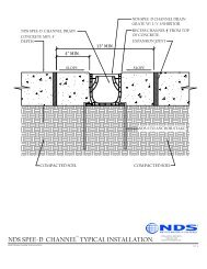
DURA SLOPE CHANNEL DRAINS<br />
PRE-SLOPED CHANNEL<br />
The following installation instructions are recommendations for typical installations. Please refer to project<br />
plans and specs for any deviation to these instructions.<br />
1 Excavate a trench for the channels<br />
Excavate a trench with a minimum concrete- surround, by load class:<br />
Note: The channel must be recessed 1/8” for pedestrian traffic and 1/4” for vehicular traffic.<br />
2 Lay the channels alongside the trench<br />
• Start the layout at the drain outlet with the deepest (highest numbered) channel section, proceeding to the shallowest<br />
(lowest numbered) channel section.<br />
• Point the arrows on each channel section towards the drain outlet.<br />
3 Locate the expansion joints<br />
Plan to install expansion joints parallel and perpendicular to channel according<br />
to plan specification. Locate perpendicular expansion joints crossing the<br />
channel at the channel joints (if possible).<br />
4 Assemble the drain outlet<br />
Expansion joints<br />
• Assemble the drain outlet with DS-224 End Cap, End Outlet DS-227, or using a Catch Basin DS-340.<br />
• Use End Cap DS-224 at the shallowest end of the run.<br />
• Set a string line in trench along each side of where channel will be placed, at final elevation of channel. If using ductile<br />
iron frame place string line 1” below finished grade to accommodate the frame.<br />
5 Assemble the channels<br />
The outlet will be at the deepest end. Assemble the channel section from the deepest to<br />
the shallowest.<br />
• Place a bead of butyl caulking or silicone sealant in the channel’s joint or groove (if a<br />
water tight seal is required).<br />
• Snap the channel sections together in multiples of two.<br />
Joined channels<br />
Note: If using Ductile Iron Frames skip to Step 5A.<br />
• Remove the screws from the end of the Blank Grate Insert located on the male side of the channel (do not<br />
remove the center screws from the insert). Start at the drain outlet.<br />
• Loosen the center screws on the Blank Grate Insert; slide the Insert in the direction of the male end (downstream)<br />
so it overhangs or is staggered.<br />
• Align channel with Blank Grate Insert for straightness. Use self tapping screws to fasten<br />
the Inserts to the channel; ensure the ends are flush with the edge of the Insert.<br />
Cover the slots on the Insert with tape to prevent concrete from getting into the channel.<br />
• Place the pre-assembled channel sections in the trench beginning from the outlet<br />
end.<br />
Tip: Cover screw heads and the slots in the Blank Grate Insert with tape for<br />
easy removal after the concrete is poured.<br />
5A If using Ductile Iron Frame: Assemble the channels<br />
• Assemble the channels. Snap the channel sections together in multiples of two.<br />
• Remove all Blank Grate Inserts from all channel sections.<br />
Offset Blank<br />
Grate Inserts<br />
Channels<br />
connected<br />
Offset blank grate inserts<br />
• Secure the Ductile Iron Frames to the channel using the DS-123 screws. Install iron grates using DS-225 screws.<br />
• Apply a covering or tape to the grates for protection and to prevent concrete from entering the channel.<br />
46<br />
Note: All dimensions are nominal. All weights are for shipping purposes only. Availability is subject to change.<br />
To place an order, visit: ndspro.net, fax: 1-800-726-1998 or call 1-800-726-1994.