

IQ204/ADL Autodialling Controller Data Sheet - Trend
IQ204/ADL Autodialling Controller Data Sheet - Trend
IQ204/ADL Autodialling Controller Data Sheet - Trend

Create successful ePaper yourself
Turn your PDF publications into a flip-book with our unique Google optimized e-Paper software.
6 <br />
6 <br />
4 <br />
4 <br />
6 <br />
6 <br />
4 <br />
4 <br />
" 8<br />
8<br />
, &<br />
) &<br />
, %<br />
) %<br />
" 8<br />
, $<br />
) $<br />
, #<br />
) #<br />
8<br />
, "<br />
) "<br />
, !<br />
) !<br />
" 8<br />
,<br />
)<br />
, <br />
) <br />
8<br />
<br />
6 :<br />
4 :<br />
1 2 3<br />
4 5 6<br />
7 8 9<br />
0<br />
<br />
6 :<br />
4 :<br />
1 2 7 6<br />
- 6 9 4 <br />
6 <br />
6 <br />
4 <br />
4 <br />
6 <br />
6 <br />
4 <br />
4 <br />
" 8<br />
8<br />
, &<br />
) &<br />
, %<br />
) %<br />
" 8<br />
, $<br />
) $<br />
, #<br />
) #<br />
8<br />
, "<br />
) "<br />
, !<br />
) !<br />
" 8<br />
,<br />
)<br />
, <br />
) <br />
8<br />
OK OK NETWORK<br />
T-<br />
T-<br />
T+<br />
T+<br />
R- TX<br />
R-<br />
R+<br />
TX<br />
R+<br />
T-<br />
T-<br />
RX<br />
T+ RX<br />
T+<br />
R-<br />
R-<br />
R+<br />
R+<br />
24V<br />
24V<br />
0V<br />
0V<br />
D8<br />
D8<br />
A8<br />
A8<br />
D7<br />
D7<br />
A7<br />
A7<br />
24V<br />
24V<br />
D6<br />
D6<br />
A6<br />
A6<br />
D5<br />
D5<br />
A5<br />
A5<br />
0V<br />
0V<br />
D4<br />
D4<br />
A4<br />
A4<br />
D3<br />
D3<br />
A3<br />
A3<br />
24V<br />
24V<br />
D2<br />
D2<br />
A2<br />
A2<br />
D1<br />
D1<br />
A1<br />
A1<br />
0V<br />
0V<br />
INPUT<br />
1 2 3<br />
4 5 6<br />
7 8 9<br />
0<br />
NDP<br />
" 8<br />
8<br />
* &<br />
8<br />
* %<br />
8<br />
* $<br />
8<br />
* #<br />
8<br />
* "<br />
8<br />
* !<br />
8<br />
*<br />
8<br />
* <br />
8<br />
2 9 - 4 1<br />
-<br />
<br />
<br />
- $ )<br />
8<br />
7 6 2 7 6<br />
8 <br />
8 <br />
)<br />
*<br />
+<br />
,<br />
" 8<br />
8<br />
* &<br />
8<br />
* %<br />
8<br />
* $<br />
8<br />
* #<br />
8<br />
* "<br />
8<br />
* !<br />
8<br />
*<br />
8<br />
* <br />
8<br />
POWER IN<br />
24V<br />
0V<br />
B8<br />
0V<br />
B7<br />
0V<br />
B6<br />
0V<br />
B5<br />
0V<br />
B4<br />
0V<br />
B3<br />
0V<br />
B2<br />
0V<br />
B1<br />
0V<br />
E<br />
N<br />
(0V)<br />
~(24V)<br />
E160 mA<br />
0V<br />
(0V)<br />
OUTPUT<br />
A<br />
B<br />
C<br />
D<br />
24V<br />
0V<br />
B8<br />
0V<br />
B7<br />
0V<br />
B6<br />
0V<br />
B5<br />
0V<br />
B4<br />
0V<br />
B3<br />
0V<br />
B2<br />
0V<br />
B1<br />
0V<br />
, 2<br />
DP<br />
<strong>IQ204</strong>/<strong>ADL</strong><br />
<strong>Data</strong> <strong>Sheet</strong><br />
HARDWARE<br />
Box: The unit is enclosed in a metal box. This provides a robust<br />
construction, and in conjunction with the multi-layer board provides<br />
excellent EMC performance. The box is mounted using the four 'u' slots<br />
on the outside of the unit. There are four holes in the cover normally<br />
covered by labels which can be used for fitting two lengths of DIN rail.<br />
Connectors: Two part connectors are used throughout. Input<br />
power connectors have enhanced creepage and clearance.<br />
Earthing (grounding) flanges are provided adjacent to the I/O<br />
terminals to terminate cable screens.<br />
Power: The <strong>IQ204</strong> can be supplied in 230 Vac or 24 Vac versions.<br />
Displays: The <strong>IQ204</strong>/<strong>ADL</strong> may have an optional 2-line display<br />
panel (HDP or FPK) connected. If the modem is removed from<br />
the local supervisor connector, either a local PC (e.g. supervisor),<br />
a Network Display Panel (NDP), or a Generic Display Panel<br />
(GDP+ - which can be either RS232 or RS485) may be connected.<br />
2-line Display Panel A 2-line display panel (FPK or HDP) can be<br />
mounted externally and connected using the display panel<br />
connector, to provide access to parameters within the controller.<br />
It gives the only indication of the call connection status, so it is<br />
useful to have a display panel fitted either permanently or<br />
temporarily for commissioning purposes.<br />
Fusing: The controller has no replaceable fuses: protection is<br />
provided by means of a self-resetting thermally protected<br />
transformer. The 24 Vac version has a solid state multifuse.<br />
<br />
" 8 <br />
" 8 <br />
" 8 <br />
Network: The network terminals will facilitate connection of 4 wire,<br />
or 2 wire cables. The standard IQ system current loop node features<br />
are included (Lan OK, TX and RX indicators, bypass relay, network<br />
alarm generation). There is also the facility for connection of a<br />
supervisor, network display panel, or GDP+ to the network using the<br />
controller without the need for additional node controllers.<br />
Modem: The modem is connected to the RS232 RJ11 supervisor port<br />
by the adaptor cable supplied with the <strong>IQ204</strong>/<strong>ADL</strong>. It is capable of<br />
V22bis (2400 bps), V22 (1200 bps), and V21 (300 bps) and supports<br />
V25 active handshake protocol. It will communicate only with a TMN<br />
(TMN v4 or greater, V22bis). It consumes 20 mA maximum (equivalent)<br />
from 24 V input power when in use. The modem is compatible with most<br />
major networks in the world. It complies with FCC Part 68 USA, IC CS03<br />
Canada, TS 002 Australia, and CTR21, for use with all telephone networks<br />
of the European Union.<br />
Address/Baud rate switch: The address on the Lan is set by<br />
poles 1 to 7 in the range 11 to 117 and must be unique on the Lan.<br />
(The normal address range is allowed (1, 4 to 9, 11 to 119), but<br />
if another controller on the local network is to dial out using the<br />
modem, its address must also be valid; additionally the default<br />
address setting mechanism uses the address switch plus one<br />
rule for address 11 and greater so this is recommended as the<br />
lowest address, resulting in a recommended range of 11 to 117).<br />
The baud rate is set by poles 8 to 10 in the range 1k2, 9k6, 19k2,<br />
and must match the other nodes on the Lan.<br />
The address and baud rate switch may also be used to perform<br />
a strategy cleardown; this is done by setting all the poles to zero<br />
before power up (see installation instructions, TG200490 sheet<br />
4 and IQ Configuration Manual Addendum). For this reason the<br />
address should normally be set to non-zero.<br />
Local Supervisor Port: By default the local supervisor port is set<br />
to RS232 and intended for connection to the modem. If the modem<br />
is disconnected the RS232 interface (RJ11 socket) can be used for<br />
direct connection of a local supervisor, NDP, or GDP+/RS232.<br />
The local supervisor port can be switched to either RS232 or<br />
RS485 by internal link (J5). The RS485 interface (RJ45 socket)<br />
is for direct connection of a GDP+/RS485; to use it, a flange<br />
covering the RJ45 connector must be bent and snapped off.<br />
The RS232 J11 connects using adapter cable CABLE/EJ101442<br />
to a local supervisor, using adapter cable EJ104029 to an NDP,<br />
or using a special adaptor cable (e.g. RS477-450, 3 meters) to<br />
a GDP+/RS232. The RS485 RJ45 connects using a special<br />
adaptor cable (RJ45 to RJ45 plugs, not crossed-over e.g. RS446-<br />
686, 3 m, 3.25 yds) to a GDP+/RS485. The RS485 interface gives<br />
increased distance compare to RS232 (up to about 100 m, 110 yds).<br />
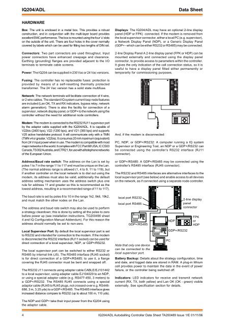
And, if the modem is disconnected:<br />
PC, NDP, or GDP+/RS232: A computer running a IQ system<br />
Supervisor or Engineering Tool, an NDP or a GDP+/RS232 can<br />
be connected using the controller’s RS232 interface (RJ11<br />
connector).<br />
or GDP+/RS485: A GDP+/RS485 may be connected using the<br />
controller's RS485 interface (RJ45 connector).<br />
The RS232 and RS485 interfaces are alternative interfaces to the<br />
local supervisor port (see below) and enable access to all devices<br />
on the network, as if connected using a separate node controller.<br />
local port RS232<br />
local port RS485<br />
GDP+/RS485<br />
Note that only one device<br />
can be connected to the<br />
local supervisor port.<br />
NDP<br />
Battery Backup: Details about the strategy configuration, time<br />
and date, and logged data are stored in RAM. A plug-in lithium<br />
cell provides power to maintain the data in the event of power<br />
failure, or the controller being switched off.<br />
Indicators: LED indicators for receive and transmit network<br />
current (RX, TX, both yellow) and Lan OK (OK - green) visible<br />
externally. See specification section for details.<br />
PC<br />
L ~<br />
24 V (24V) ~ ~<br />
GDP+/RS232<br />
2-line display<br />
panel<br />
connector<br />
FPK<br />
or<br />
HDP<br />
The NDP and GDP+ take their input power from the <strong>IQ204</strong> using<br />
the adaptor cable.<br />
4 <strong>IQ204</strong>/<strong>ADL</strong> Autodailling <strong>Controller</strong> <strong>Data</strong> <strong>Sheet</strong> TA200489 Issue 1/E 01/11/06


