LESER High Performance Safety Valve ... - Pressure Systems
LESER High Performance Safety Valve ... - Pressure Systems
LESER High Performance Safety Valve ... - Pressure Systems

Create successful ePaper yourself
Turn your PDF publications into a flip-book with our unique Google optimized e-Paper software.
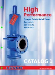
<strong>High</strong><br />
<strong>Performance</strong><br />
Flanged <strong>Safety</strong> Relief <strong>Valve</strong>s<br />
Series 441 Full nozzle<br />
Series 458<br />
CATALOG 2<br />
The-<strong>Safety</strong>-<strong>Valve</strong>.com
NH 3<br />
HCL<br />
Product Range<br />
<strong>LESER</strong> <strong>Safety</strong> <strong>Valve</strong>s for every industrial application<br />
<strong>High</strong><br />
<strong>Performance</strong><br />
Compact<br />
<strong>Performance</strong><br />
Series 441 Full nozzle<br />
Type 441, 442 Full nozzle DIN<br />
Type 441, 442 Full nozzle ANSI<br />
API<br />
Series 458<br />
Type 455, 456<br />
Type 457, 458<br />
Clean<br />
Service<br />
H 2<br />
SO 4<br />
HNO 3<br />
Critical<br />
Service<br />
Series 441<br />
Type 441, 442 DIN<br />
Type 441, 442 ANSI<br />
Modulate<br />
Action<br />
Series XXL<br />
Type 441, 442 XXL<br />
Best<br />
Availability<br />
Series 444<br />
Type 444 DIN<br />
Type 444 ANSI<br />
Please refer to<br />
<strong>High</strong> <strong>Performance</strong><br />
Catalog 1
General<br />
General<br />
Type 441, 442<br />
Full nozzle DIN<br />
DN 20, 40, 50<br />
Set pressure 0,1 – 40 bar, 1,5 – 580 psig<br />
Flanges according to DIN EN 1092<br />
Type 441, 442<br />
Full nozzle ANSI<br />
<strong>Valve</strong> size 1" – 4"<br />
Set pressure 0,1 – 51 bar, 1,5 – 740 psig<br />
Flanges according to ASME B16.5<br />
Type 441, 442 Full nozzle DIN<br />
Type 441, 442 Full nozzle ANSI<br />
Type 455, 456<br />
DN 25 – 100, 1" – 4"<br />
Set pressure 2,5 – 100 bar, 36 – 1450 psig<br />
Flanges according to DIN EN 1092 and ASME B16.5<br />
Type 456, 456<br />
Type 457, 458<br />
DN 25 – 150, 1" – 6"<br />
Set pressure 2,5 – 300 bar, 36 – 4350 psig<br />
Flanges according to DIN EN 1092 and ASME B16.5<br />
Type 457, 458<br />
Options<br />
Options
Contents<br />
Overview<br />
Chapter/Page<br />
General 00/01<br />
Applications, General design features 00/02<br />
<strong>Valve</strong> finder 00/03<br />
<strong>Valve</strong> selection 00/05<br />
How to use:<br />
Signs and symbols, Flange drillings and facings 00/07<br />
How to use:<br />
Determination of coefficient of discharge K dr<br />
/α w<br />
00/08<br />
How to use: Capacity sheets 00/09<br />
<strong>LESER</strong> Effective Orifice LEO S/G<br />
00/11<br />
<strong>LESER</strong> Effective Orifice LEO L<br />
00/12<br />
Sour gas service 00/13<br />
Type 441, 442 Full nozzle ANSI 07/01<br />
Materials<br />
• Conventional design 07/02<br />
• Balanced bellows design 07/04<br />
How to order<br />
• Numbering system 07/06<br />
• Article numbers 07/08<br />
Dimensions and weights<br />
• Metric Units 07/10<br />
• US Units 07/11<br />
<strong>Pressure</strong> temperature ratings<br />
• Metric Units 07/12<br />
• US Units 07/13<br />
Flange drillings and facings 07/14<br />
Order information – Spare parts 07/15<br />
Available options 07/16<br />
Approvals 07/17<br />
Capacities<br />
• Steam [Metric Units + US Units] 07/18<br />
• Air [Metric Units + US Units] 07/19<br />
• Water [Metric Units + US Units] 07/20<br />
Determination of coefficient of discharge K dr /α w 07/21<br />
<strong>LESER</strong> Type<br />
Chapter/Page<br />
Type 441, 442 Full nozzle DIN 06/01<br />
Materials<br />
• Conventional design 06/02<br />
• Balanced bellows design 06/04<br />
How to order<br />
• Numbering system 06/06<br />
• Article numbers 06/08<br />
Dimensions and weights<br />
• Metric Units 06/10<br />
• US Units 06/11<br />
<strong>Pressure</strong> temperature ratings<br />
• Metric Units 06/12<br />
• US Units 06/13<br />
Flange drillings and facings 06/14<br />
Order information – Spare parts 06/15<br />
Available options 06/16<br />
Approvals 06/17<br />
Capacities<br />
• Steam [Metric Units + US Units] 06/18<br />
• Air [Metric Units + US Units] 06/19<br />
• Water [Metric Units + US Units] 06/20<br />
Determination of coefficient of discharge K dr /α w 06/21<br />
Type 455, 456 08/01<br />
Materials<br />
• Conventional design 08/02<br />
• Balanced bellows design 08/04<br />
How to order<br />
• Numbering system 08/06<br />
• Article numbers 08/08<br />
Dimensions and weights<br />
• Metric Units 08/10<br />
• US Units 08/11<br />
<strong>Pressure</strong> temperature ratings<br />
• Metric Units 08/12<br />
• US Units 08/13<br />
Flange drillings and facings 08/14<br />
Order information – Spare parts 08/15<br />
Available options 08/16<br />
Approvals 08/17<br />
Capacities<br />
• Steam [Metric Units + US Units] 08/18<br />
• Air [Metric Units + US Units] 08/19<br />
• Water [Metric Units + US Units] 08/20<br />
Determination of coefficient of discharge K dr /α w 08/21<br />
refer to catalog<br />
Series 441<br />
refer to catalog<br />
Series 444<br />
Type 441<br />
Cap H2<br />
Closed bonnet<br />
Conventional design<br />
Type 441<br />
Packed lever H4<br />
Closed bonnet<br />
Conventional design<br />
Type 441<br />
Plain lever H3<br />
Closed bonnet<br />
Conventional design<br />
Type 444<br />
Packed lever H4<br />
Closed bonnet<br />
Conventional design<br />
Type 441<br />
Cap H2<br />
Closed bonnet<br />
Balanced bellows design<br />
Type 442<br />
Plain lever H3<br />
Open bonnet<br />
Conventional design<br />
Type 444<br />
Cap H2<br />
Closed bonnet<br />
Conventional design
Contents<br />
Type 457, 458 09/01<br />
Materials<br />
• Conventional design 09/02<br />
• Balanced bellows design 09/04<br />
How to order<br />
• Numbering system 09/06<br />
• Article numbers 09/08<br />
Dimensions and weights<br />
• Metric Units 09/10<br />
• US Units 09/11<br />
<strong>Pressure</strong> temperature ratings<br />
• Metric Units 09/12<br />
• US Units 09/13<br />
Flange drillings and facings 09/14<br />
Order information – Spare parts 09/16<br />
Available options 09/18<br />
Approvals 09/19<br />
Capacities<br />
• Steam [Metric Units + US Units] 09/20<br />
• Air [Metric Units + US Units] 09/22<br />
• Water [Metric Units + US Units] 09/24<br />
Determination of coefficient of discharge K dr /α w 09/26<br />
Type 441, 442<br />
Materials<br />
How to order<br />
Dimensions and weights<br />
<strong>Pressure</strong> temperature ratings<br />
Flange drillings and facings<br />
Order information – Spare parts<br />
Available options<br />
Approvals<br />
Capacities<br />
Determination of coefficient of discharge K /α dr w<br />
Type 441, 442 XXL<br />
Materials<br />
How to order<br />
Dimensions and weights<br />
<strong>Pressure</strong> temperature ratings<br />
Flange drillings and facings<br />
Order information – Spare parts<br />
Available options<br />
Approvals<br />
Capacities<br />
Determination of coefficient of discharge K dr /α w<br />
refer to catalog<br />
Series 441<br />
refer to catalog<br />
Series XXL<br />
Options 99/01<br />
Overview 99/02<br />
Caps and Levers 99/04<br />
Caps and Levers bolted 99/06<br />
Metal seat 99/08<br />
Soft seal disc 99/10<br />
Soft seal 99/12<br />
Balanced bellows 99/14<br />
<strong>High</strong> temperature equipment 99/16<br />
Elastomer bellows 99/17<br />
Disc 99/18<br />
Heating jacket 99/20<br />
O-ring damper 99/22<br />
Lift indicator 99/24<br />
Lift restriction 99/25<br />
Type 444<br />
Materials<br />
How to order<br />
Dimensions and weights<br />
<strong>Pressure</strong> temperature ratings<br />
Flange drillings and facings<br />
Order information – Spare parts<br />
Available options<br />
Approvals<br />
Capacities<br />
Determination of coefficient of discharge K /α dr w<br />
refer to catalog<br />
Series 444<br />
First in safety<br />
Fax Order<br />
refer to catalog<br />
Series XXL<br />
Type 441 XXL<br />
Bolted lifting device H6<br />
Closed bonnet<br />
Conventional and balanced<br />
bellows design<br />
Type 441 Full Nozzle<br />
Cap H2<br />
Closed bonnet<br />
Conventional design<br />
Type 456<br />
Packed lever H4<br />
Closed bonnet<br />
Conventional design<br />
Type 457<br />
Plain lever H3<br />
Open bonnet<br />
Conventional design<br />
Type 458<br />
Cap H2<br />
Closed bonnet<br />
Balanced bellows design
General<br />
General Information<br />
<strong>LESER</strong> – <strong>High</strong> <strong>Performance</strong> <strong>Safety</strong> <strong>Valve</strong>s<br />
The <strong>High</strong> <strong>Performance</strong> product group represents<br />
✓ <strong>High</strong> capacity related to the safety valve size<br />
✓ <strong>High</strong> customisability<br />
✓ Excellent price / performance ratio<br />
<strong>LESER</strong>´s <strong>High</strong> <strong>Performance</strong> <strong>Safety</strong> <strong>Valve</strong>s<br />
• Are designed to meet all industrial applications.<br />
• Open rapidly with an overpressure of 5 % to the full design lift.<br />
• Are used particularly for vapours and gases where the maximum<br />
mass flow has to be discharged rapidly.<br />
• Have a maximum blowdown of minus 10 % for steam/gas<br />
service and minus 20 % for liquid service.<br />
• Are one of the best selling spring loaded safety valve worldwide.<br />
• Are developed in a close cooperation with plant engineers<br />
and service specialists.<br />
• Serve for protection of processes and equipment.<br />
• Are approved by all important approval organisations worldwide<br />
which ensures the worldwide applicability e.g.:<br />
• European Community: CE-marking acc. to <strong>Pressure</strong><br />
Equipment Directive (PED) 97 / 23 / EC and EN ISO 4126-1<br />
• USA: UV-stamp acc. to ASME Section VIII Division 1,<br />
National Board certified capacities<br />
• Germany: VdTÜV approval acc. to PED, EN ISO 4126-1,<br />
TÜV SV 100 and AD 2000-Merkblatt A2<br />
• Canada: Canadian Registration Number acc. to the<br />
requirements of particular provinces<br />
• China: AQSIQ based on the approval acc. to ASME<br />
Section VIII Division 1 and AD 2000-Merkblatt A2<br />
Furthermore, all <strong>LESER</strong> <strong>High</strong> <strong>Performance</strong> safety valves are<br />
designed, marked, produced and approved acc. to the requirements<br />
of the following regulations (directives, codes, rules and<br />
standards).<br />
EN ISO 4126-7, EN 12266-1/-2, EN 1092 Part I and II flanging<br />
ASME PTC 25, ASME-Code Sec. II, ASME B 16.34 and ASME<br />
B16.5- flanging, API Std. 527, API RP 576<br />
AD 2000-Merkblatt A4, AD 2000-Merkblatt HP0, TRD 110,<br />
TRD 421, TRD 721<br />
00/01 LWN 488.01-E
General Information<br />
General<br />
Applications<br />
General Design Features<br />
<strong>LESER</strong> – <strong>High</strong> <strong>Performance</strong> <strong>Safety</strong> <strong>Valve</strong>s<br />
Are the ultimate solution for all industrial<br />
applications for steam, gas and liquid.<br />
<strong>LESER</strong>´s <strong>High</strong> <strong>Performance</strong> <strong>Safety</strong> <strong>Valve</strong>s<br />
Offer a large variety of types, materials and options<br />
to suit any application:<br />
Typical applications for<br />
<strong>LESER</strong> <strong>High</strong> <strong>Performance</strong> <strong>Safety</strong> <strong>Valve</strong>s are:<br />
Series 441<br />
• Protection of chemical processes and equipment<br />
(e.g. distillation columns)<br />
• Heat exchangers<br />
• Low and medium pressure steam<br />
• Blowers and turbo compressors<br />
Series XXL<br />
• Low pressure steam at big power stations<br />
• Capacities beyond the limits of API and Series 441<br />
Series 444<br />
• OEM in dying machines or filter constructions<br />
• Stainless steel applications up to 16 bar / 232 psig<br />
Series 441 Full Nozzle<br />
• Same applications like Series 441 when<br />
full nozzle design is preferred.<br />
• Special requirement for nozzle material<br />
Series 458<br />
• Power stations and industrial superheated<br />
steam generation<br />
• Required flange classes ≥ PN 63 / CL600<br />
• Protection of high pressure Chemical processes,<br />
e.g. NH 3 synthesis, CO 2 extraction<br />
• Desalination plants<br />
• 14 valve sizes from DN 20 to DN 400 – 3 / 4" to 16"<br />
provide a high connectivity to the application<br />
• Inlet pressure ratings PN 16 to PN 400 / class 150 to<br />
2500 to fit all required design pressures<br />
• Orifice sizes from E to > 3 x T cover all capacity<br />
requirements<br />
• Large variety of body materials; e.g.<br />
• 0.6025 / grey iron<br />
• 0.7043 / ductile iron<br />
• 1.0619 / WCB<br />
• 1.4408 / CF8M<br />
• 1.7357 / WC6<br />
can be selected acc. to the application<br />
• Set pressures from 0,1 to 300 bar / 1,5 to 4350 psig<br />
make this product group suitable for all industrial processes<br />
• Operating temperatures from -270 to 550 °C / -454 to<br />
1022 °F cover a wide range of applications<br />
• One design and spring (single trim) for steam, gas and<br />
liquid applications reduces the number of spare parts and<br />
ensure an easier maintenance.<br />
• <strong>High</strong> capacity compared to the API requirements to reduce<br />
installation costs<br />
• Ringless design needs no trim adjustments for easy<br />
maintenance<br />
• One-piece spindle reduces friction which is leading to high<br />
operation accuracy<br />
• Self-draining body design, avoids residues and reduces<br />
corrosion<br />
<strong>LESER</strong>´s <strong>High</strong> <strong>Performance</strong> <strong>Safety</strong> <strong>Valve</strong>s<br />
can be customized with a great variety of options, e.g.<br />
• O-ring disc for superior tightness<br />
• Stellited or hardened metal sealing for longer product life<br />
• Stainless steel bellows for back pressure compensation<br />
• Heating jacket for applications with high viscosity fluids<br />
• Every part can be replaced by other material acc. to<br />
customer specification<br />
LWN 488.01-E<br />
00/02
General<br />
<strong>Valve</strong> finder<br />
How to find the right Product Group<br />
Orifice > F<br />
<strong>High</strong><br />
<strong>Performance</strong><br />
Required<br />
Orifice letter<br />
Orifice < F<br />
Compact<br />
<strong>Performance</strong><br />
No<br />
Liquid application<br />
and low capacity depending<br />
on <strong>Valve</strong> size<br />
Yes<br />
Modulate<br />
Action<br />
No<br />
API specified application<br />
Yes<br />
API<br />
No<br />
Critical Service / <strong>High</strong> Corrosive<br />
application<br />
Yes<br />
Critical<br />
Service<br />
No<br />
Clean Service application<br />
Yes<br />
Clean<br />
Service<br />
How to find<br />
the right <strong>Safety</strong> <strong>Valve</strong><br />
Product Group<br />
00/03 LWN 488.01-E
<strong>Valve</strong> finder<br />
How to find the right <strong>Safety</strong> <strong>Valve</strong><br />
General<br />
DIN EN ISO<br />
Type 441 DIN<br />
Type 442 DIN<br />
Flange standard<br />
ASME B16.5<br />
Type 441 ANSI<br />
Type 442 ANSI<br />
No<br />
DIN EN ISO<br />
Type 441 Full nozzle DIN<br />
Type 442 Full nozzle DIN<br />
Full nozzle-design required<br />
Yes<br />
ASME B16.5<br />
Type 441 Full nozzle ANSI<br />
Type 442 Full nozzle ANSI<br />
≤ PN40 / CL300<br />
≥ PN63 / ≥ CL600<br />
Series 458<br />
Flange rating<br />
≤ DN 150 / 6"<br />
Semi nozzle up to<br />
100 bar / 1450 psig<br />
Full nozzle up to<br />
400 bar / 5800 psig<br />
Type 455<br />
Type 456<br />
Type 457<br />
Type 458<br />
<strong>Valve</strong> size, inlet<br />
≥ DN 200 / 8"<br />
Type 441 XXL<br />
Type 442 XXL<br />
General industry<br />
Stainless steel<br />
OEM-application<br />
up to<br />
16 bar /<br />
232 psig<br />
DIN EN ISO<br />
ASME B16.5<br />
Type 444 DIN<br />
Type 444 ANSI<br />
How to find<br />
the right <strong>High</strong> <strong>Performance</strong><br />
<strong>Safety</strong> <strong>Valve</strong><br />
LWN 488.01-E<br />
00/04
General<br />
<strong>Valve</strong> selection<br />
<strong>Valve</strong> size<br />
Type 441, 442<br />
441, 442<br />
441, 442<br />
444<br />
444<br />
441, 442<br />
441, 442<br />
455, 456 457, 587<br />
DIN<br />
ANSI<br />
XXL<br />
DIN<br />
ANSI<br />
Full nozzle<br />
Full nozzle<br />
DIN<br />
ANSI<br />
min.<br />
max.<br />
DN 20 (DN 25) DN 200 DN 25 – DN 25 (DN 25) DN 25 DN 25<br />
(¾") 1" 8" – 1" (1") 1" 1" 1"<br />
DN 200 (DN 100) DN 400 DN 80 – DN 50 (DN 100) DN 100 DN 150<br />
(8") 4" 16" – 3" (2") 4" 4" 6"<br />
Materials<br />
Type 441, 442<br />
441, 442<br />
441, 442<br />
444<br />
444<br />
441, 442<br />
441, 442<br />
455, 456 457, 587<br />
DIN<br />
ANSI<br />
XXL<br />
DIN<br />
ANSI<br />
Full nozzle<br />
Full nozzle<br />
DIN<br />
ANSI<br />
0.6025 Grey iron ✓ – – – – – – – –<br />
0.7043 Ductile Gr. 60-40-18 ✓ – – – – – – – –<br />
1.0619 WCB ✓ ✓ – – – – – – –<br />
1.0460 / 1.0425 Carbon steel – – ✓ – – ✓ ✓ ✓ ✓<br />
1.4408 CF8M ✓ ✓ – – – – – – –<br />
1.4404 316L – – – ✓ ✓ ✓ ✓ – –<br />
1.4581 CF10M – – – – – – – ✓ ✓<br />
1.4571 316Ti – – ✓ – – – – – –<br />
1.7357 WC6 – – – – – – – ✓ ✓<br />
Set pressure<br />
Type 441, 442<br />
441, 442<br />
441, 442<br />
444<br />
444<br />
441, 442<br />
441, 442<br />
455, 456 457, 587<br />
DIN<br />
ANSI<br />
XXL<br />
DIN<br />
ANSI<br />
Full nozzle<br />
Full nozzle<br />
DIN<br />
ANSI<br />
Metric Units min. [bar] 0,1 0,1 0,2 0,1 0,1 0,1 0,1 2,5 2,5<br />
US Units min. [psig] 1,5 3 3 1,5 1,5 1,5 1,5 36 36<br />
Metric Units max. [bar] 40 51 25 16 16 40 51 100 300<br />
US Units max. [psig] 580 740 360 232 232 580 740 1450 4350<br />
00/05 LWN 488.01-E
<strong>Valve</strong> selection<br />
General<br />
Temperature range<br />
Type 441, 442<br />
DIN<br />
441, 442<br />
ANSI<br />
441, 442<br />
XXL<br />
444<br />
DIN<br />
444<br />
ANSI<br />
441, 442<br />
Full nozzle<br />
DIN<br />
441, 442<br />
Full nozzle<br />
ANSI<br />
455, 456 457, 587<br />
acc. to DIN EN min. [°C] -270 -270 -196 -45 -45 -270 -270 -85 -270<br />
max. [°C] 450 450 550 200 200 450 450 550 550<br />
min. [°F] -454 -454 -321 -49 -49 -454 -454 -121 -454<br />
max. [°F] 842 842 1022 392 392 842 842 1022 1022<br />
acc. to ASME min. [°C] -268 -268 -184 -45 -45 -268 -268 -129 -268<br />
max. [°C] 538 538 427 200 200 538 538 538 538<br />
min. [°F] -450 -450 -300 -49 -49 -450 -450 -20 -450<br />
max. [°F] 1000 1000 800 392 392 1000 1000 1000 1000<br />
Capacity<br />
Type 441, 442<br />
DIN<br />
441, 442<br />
ANSI<br />
441, 442<br />
XXL<br />
444<br />
DIN<br />
444<br />
ANSI<br />
441, 442<br />
Full nozzle<br />
DIN<br />
441, 442<br />
Full nozzle<br />
ANSI<br />
455, 456 457, 587<br />
LEO S/G<br />
min. 0,283 0,462 23,8 0,462 0,462 0,462 0,462 0,399 0,224<br />
LEO S/G<br />
max. 23,8 7,39 76,0 4,78 4,78 1,85 7,39 5,46 11,4<br />
Orifice S/G<br />
min. 1,4 x E 1,5 x F 1,5 x R 1,5 x F 1,5 x F 1,5 x F 1,5 x F 1,3 x F 1,1 x E<br />
Orifice S/G<br />
max. 1,5 x R 1,2 x P 3,0 x T 1,1 x N 1,1 x N 1,0 x K 1,2 x P 1,3 x N 1,0 x Q<br />
LEO L<br />
min. 0,316 0,516 26,6 0,516 0,516 0,516 0,516 0,429 0,241<br />
LEO L<br />
max. 26,6 8,26 84,9 5,34 5,34 2,07 8,26 5,87 10,9<br />
Orifice L<br />
min. 1,0 x F 1,0 x G 1,0 x T 1,0 x G 1,0 x G 1,0 x G 1,0 x G 1,4 x F 1,2 x E<br />
Orifice L<br />
max. 1,0 x T 1,3 x P 33 x T 1,2 x N 1,2 x N 1,1 x K 1,3 x P 1,4 x N 1,7 x P<br />
Approvals<br />
Type 441, 442<br />
DIN<br />
Country Code Media<br />
441, 442<br />
ANSI<br />
441, 442<br />
XXL<br />
444<br />
DIN<br />
444<br />
ANSI<br />
441, 442<br />
Full nozzle<br />
DIN<br />
441, 442<br />
Full nozzle<br />
ANSI<br />
455, 456 457, 587<br />
Europe<br />
Germany<br />
United<br />
States<br />
DIN EN ISO 4126-1<br />
CE-marking<br />
AD 2000-<br />
Merkblatt A2<br />
ASME VIII<br />
S/G/L<br />
S/G/L<br />
072020111Z 072020111Z 072020111Z 072020111Z 072020111Z 072020111Z 072020111Z 072020111Z 072020111Z<br />
0008/0/08-2 0008/0/08-2 0008/0/08-2 0008/0/08-2 0008/0/08-2 0008/0/08-2 0008/0/08-2 0008/0/11 0008/0/11<br />
TÜV SV<br />
576<br />
TÜV SV<br />
576<br />
TÜV SV<br />
576<br />
TÜV SV<br />
576<br />
TÜV SV<br />
576<br />
TÜV SV<br />
576<br />
TÜV SV<br />
576<br />
S/G M37044 M37044 M37044 M37044 M37044 M37044 M37044<br />
L M37055 M37055 M37055 M37055 M37055 M37055 M37055<br />
TÜV SV<br />
934<br />
M37066<br />
M37088<br />
M37077<br />
M37099<br />
TÜV SV<br />
934<br />
M37066<br />
M37088<br />
M37077<br />
M37099<br />
Canada CRN S/G/L OG1182.9C OG1182.9C OG1182.9C OG1182.9C OG1182.9C OG1182.9C OG1182.9C – –<br />
China CSBQTS S/G/L 02301T 02301T 02301T 02301T 02301T 02301T 02301T 02301T 02301T<br />
Russia DIN GOST GOSGOTTECHNADZOR ✓ ✓ ✓ ✓ ✓ – – ✓ ✓<br />
Classification societies<br />
Bureau Veritas BV ✓ ✓ ✓ – – – – – –<br />
Det Norske Veritas DNV ✓ ✓ – – – – – – –<br />
Germanischer Lloyd GL ✓ ✓ ✓ – – – – – –<br />
Lloyd`s register EMEA LREMEA ✓ ✓ ✓ – – – – – –<br />
Registro Italiano Navale RINA ✓ ✓ up to DN 250 – – – – – –<br />
LWN 488.01-E<br />
00/06
General<br />
How to use<br />
General signs and symbols<br />
*<br />
✓<br />
–<br />
This option is covered by standard design<br />
Available<br />
Not possible<br />
Signs and symbols for flange drillings and flange facings<br />
*<br />
Standard design, no option code required<br />
( * ) Flange dimensions except flange thickness are in accordance with flange standard (e.g. ASME B16.5)<br />
Flange thickness is smaller (max. 2 mm), see “Multiple pressure rating”<br />
–<br />
Flange drilling/facing is not possible<br />
Option code for flange drilling and dimension, e.g. H50<br />
H50<br />
(H50)<br />
[H50]<br />
Flange drilling as specified in flange standard<br />
Outer flange diameter, flange thickness and height of flange facing may be larger, see “Dimensions”<br />
Flange dimensions except flange thickness are in accordance with standard<br />
Flange thickness is smaller (max. 2 mm), see “Multiple pressure rating”<br />
Flange drilling as specified in standard/flange thickness may be smaller<br />
Outer flange diameter is smaller than required, but complete back side facing for nut is assured<br />
Option code for flange facing, e.g. L36<br />
L36<br />
Flange facing as specified in flange standard<br />
General information concerning flange drillings and flange facings<br />
Flange dimensions of <strong>LESER</strong> Series 458 exceed flange dimension as mentioned in ASME / ANSI B16.5 and<br />
DIN EN 1092. This exceedance is in accordance with API Standard 526, Section 2.4.<br />
Dimensions<br />
Multiple<br />
pressure rating<br />
Smooth finish<br />
Stock finish<br />
Dimensions: “For some valve designs, the inlet raised face height may substantially exceed the nominal dimension<br />
specified in ASME / ANSI B16.5 (and DIN EN 1092). Consult the manufacturer for exact dimension.”<br />
The reason for this exceedance is:<br />
- height of nozzle placed in the inlet of valve<br />
- due to the outer diameter of the nozzle thread flange thickness has to be thicker than normal<br />
ASME / ANSI B16.5 and DIN EN 1092 dimension to achieve the required pressure rating<br />
The flange standard shows the same drilling, facing and outer diameter for several pressure ratings, e.g. PN 16 up to PN 40<br />
Due to the pressure rating of the casting <strong>LESER</strong> fulfills the requirements for flange thickness e.g. of PN 16 but not PN 40<br />
The effective MSS SP-6 (Edition 2001) does not mention “smooth finish” anymore.<br />
In MSS SP-6 (Edition 1980) “smooth finish” is defined for finishes of contact flanges as “250 µinch (6,3 µm) AARH max.”.<br />
<strong>LESER</strong> supplies flange facings according to ASME B16.5 – 1996, paragraph 6.4.4.3:<br />
“Either a serrated concentric or serrated spiral finish resulting in service finish from 125 µinch to 250 µinch average<br />
roughness shall be furnished.” This finish meets the requirements of MSS SP-6 (Edition 1980), which is not valid anymore!<br />
Stock finish is not defined in any technical standard. If purchase orders show “stock finish” <strong>LESER</strong> supplies standard<br />
facing according to DIN or ASME (marked with * in table “Flange facings” of each valve series).<br />
Materials<br />
Please find below a summary of material codes at <strong>LESER</strong>. Please note that<br />
- for every body material an inspection certificate 3.1 according to EN 10204 is available<br />
- many materials have a multiple inspection certificate 3.1.<br />
Material code<br />
Flanged safety valve body Body material is certified with 3.1 (EN 10204) for the following materials<br />
Threaded safety valve inlet body EN ASME<br />
1 Grey iron 0.6025 cast iron<br />
2 Carbon steel 1.0619 WCB, WCC<br />
4 Stainless steel 1.4408, 1.4581 CF8M (Charpy test at -196°C), CF10M<br />
5 Nodular cast iron 0.7043 ductile Gr. 60-40-18<br />
7 <strong>High</strong> temperature carbon steel 1.7357 WC6<br />
00/07 LWN 488.01-E
How to use<br />
Sample Determination of K dr /α w : Type 441, 442 Full nozzle DIN, DN 25<br />
General<br />
Type 441, 442 Full nozzle DIN<br />
Determination of coefficient of discharge<br />
in case of lift restriction or back pressure<br />
Diagram for evaluation of ratio of lift / flow diameter (h/d 0 )<br />
in reference to the coefficient of discharge (K dr /α w )<br />
1<br />
0,8<br />
K dr = α w = f (h/d 0)<br />
h = Lift [mm]<br />
d0 = Flow diameter [mm] of selected safety<br />
valve, refer to table article numbers<br />
h/d0 = Ratio of lift / flow diameter<br />
p a0 = Back pressure [bar a<br />
]<br />
p0 = Set pressure [bar a<br />
]<br />
p a0/p0 = Ratio of back pressure / set pressure<br />
Kdr = Coefficient of discharge<br />
acc. to DIN EN ISO 4126-1<br />
αw = Coefficient of discharge<br />
acc. to AD 2000-Merkblatt A2<br />
Kb = Back pressure correction factor<br />
acc. to API 520 topic 3.3<br />
0,7<br />
1a<br />
0,45<br />
Coefficient of discharge K dr / αw<br />
0,6<br />
0,5<br />
0,4<br />
0,3<br />
0,2<br />
0,1<br />
0<br />
0<br />
"S/G"<br />
0,1 0,2<br />
"L"<br />
0,3<br />
Ratio of lift / flow diameter h / d 0<br />
1b<br />
0,13<br />
Diagram for evaluation of coefficient of discharge (K dr /α w ) or K b<br />
in reference to the ratio of back pressure / set pressure (p a0 /p 0 )<br />
2<br />
0,8<br />
K dr = α w = f (p a0 /p 0 ) and K b = f (p a0 /p 0 )<br />
2b<br />
0,595<br />
0,7<br />
0,6<br />
1,0<br />
0,9<br />
0,8<br />
0,85<br />
2b<br />
0,5<br />
0,7<br />
Coefficient of discharge K dr / αw<br />
0,4<br />
0,3<br />
0,2<br />
0,1<br />
0<br />
0,2<br />
0,3<br />
0,4<br />
0,5 0,6 0,7<br />
0,8<br />
0,91<br />
0,6<br />
0,5<br />
0,4<br />
0,3<br />
0,2<br />
0,1<br />
0<br />
Back pressure correction factor K b<br />
Ratio of back pressure / set pressure p a0 / p 0<br />
2a 0,648<br />
Explanation<br />
Sample – Type 441, 442 Full nozzle DIN, DN 25 flow diameter d 0 = 23 mm, rated lift h = 5,6 mm, Kdr/αw S/G = 0,7<br />
1<br />
Diagram 1<br />
Diagram 2<br />
2<br />
Determination of the restricted lift due to reduced K dr /α w Determination of reduced K dr /α or K w b 1) due to back pressure<br />
Step Description Sample Step Description Sample<br />
Calculate the required coefficent of discharge of 1a<br />
Calculate the back pressure ratio p a0/p 0 using the 2a<br />
1 the selected safety valve. Applicable formulars<br />
1 actual values for set pressure<br />
are stated in codes and standards.<br />
K dr /α = 0,45 w and back pressure<br />
p 0 [bar a ] 0,45<br />
p a0<br />
[bar a ] 0,292 p a0/p 0 = 0,648<br />
2<br />
Select the starting point (0,45) at the Y-axis of<br />
the diagram.<br />
2<br />
Select the starting point (0,648) at the X-axis<br />
of the diagram.<br />
3<br />
Lay a horizontal line onto the ratio graph to<br />
identify the intersection point.<br />
3<br />
Lay a vertical line onto the ratio graph to<br />
identify the intersection point.<br />
4<br />
5<br />
Lay a vertical line to the X-axis to identify the<br />
ratio of lift / flow diameter (h/d 0 ).<br />
Calculate the restricted lift using the formular<br />
h = d 0 x h/d 0 . (For ordering a lift restriction<br />
please use option code J51 ref. to page 99/25)<br />
1b<br />
Lay a horizontal line to the Y-axis to<br />
K dr /α<br />
4<br />
= 0,595<br />
w<br />
identify the reduced K dr /α or K 2b<br />
h/d w 0 = 0,13 b.<br />
K = 0,85<br />
b<br />
h = 23 x 0,13<br />
h = 3,0 mm<br />
5<br />
Calculate the sizing with the established<br />
K dr /α w or K b.<br />
LWN 488.01-E<br />
1)<br />
Back pressure correction factor K b acc. to API 520 topic 3.3. For further information refer to <strong>LESER</strong> Engineering Handbook<br />
00/08
General<br />
How to use<br />
Sample Capacity sheet –<br />
How to select capacities for steam: Type 441, 442 Full nozzle DIN, DN 40<br />
Capacities – Steam<br />
Capacities for saturated steam according to AD 2000-Merkblatt A2,<br />
based on set pressure plus 10 % overpressure.<br />
9<br />
Capacities at 1 bar (14,5 psig) and below are based on 0,1 bar<br />
(1,45 psig) overpressure.<br />
Capacities for saturated steam according to ASME Section VIII (UV),<br />
based on set pressure plus 10% overpressure.<br />
Capacities at 2,07 bar (30 psig) and below are based on 0,207 bar<br />
(3 psig) overpressure.<br />
Metric Units<br />
1<br />
AD 2000-Merkblatt A2 [kg/h]<br />
DN 25 40 2 50<br />
DN O<br />
40 3 65 80<br />
Actual Orifice diameter d 0<br />
[mm] 23 37 4 46<br />
Actual Orifice area A 0<br />
[mm 2 ] 416 5 1075 1662<br />
LEO S/G<br />
* ) [inch 2 ] 0,462 1,195 6 1,847<br />
Set pressure [bar]<br />
Capacities [kg/h]<br />
0,1<br />
7<br />
0 0 0<br />
0,2 140 363 561<br />
0,5 224 579 895<br />
1 326 843 8 1302<br />
US Units<br />
ASME Section VIII [lb/h]<br />
DN I<br />
25 40 50<br />
DN O<br />
40 65 80<br />
Actual Orifice diameter d 0<br />
[inch] 0,91 1,47 1,81<br />
Actual Orifice area A 0<br />
[inch 2 ] 0,644 1,667 2,576<br />
LEO S/G<br />
* ) [inch 2 ] 0,462 1,195 1,847<br />
Set pressure [psig]<br />
Capacities [lb/h]<br />
15 757 1959 3028<br />
20 873 2259 3492<br />
30 1105 2859 4419<br />
40 1360 3519 5439<br />
* ) LEO S/G<br />
= <strong>LESER</strong> Effective Orifice steam/gas please refer to page 00/11<br />
Explanation Type 441, 442 Full nozzle DIN, DN 40<br />
No. Description Metric Units US Units Example<br />
1<br />
Code AD 2000-Merkblatt A2<br />
2<br />
Nominal diameter inlet DN I<br />
40<br />
3<br />
Nominal diameter outlet DN O<br />
65<br />
4<br />
Actual orifice diameter d 0<br />
[mm] [inch] 37<br />
5<br />
Actual orifice area A 0<br />
[mm] [inch 2 ] 1075<br />
6<br />
<strong>LESER</strong> Effective Orifice LEO S/G<br />
[inch 2 ] [inch 2 ] 1,195<br />
7<br />
Set pressure [bar g<br />
] [psig] 1<br />
8<br />
Capacity [kg/h] [lb/h] 843<br />
9<br />
Base of calculation see table page 00/10<br />
00/09 LWN 488.01-E
How to use<br />
9<br />
Base of calculation<br />
General<br />
Metric Units<br />
US Units<br />
Code<br />
Capacity calculation according to<br />
AD 2000-Merkblatt A2<br />
Capacity calculation according to<br />
ASME Section VIII (UV)<br />
Media<br />
STEAM<br />
(saturated steam)<br />
Standard<br />
conditions<br />
Steam table IAPWS-IF97<br />
IAPWS Industrial Formulation for<br />
the Thermodynamic Properties<br />
of Water and Steam<br />
[kg/h]<br />
Steam table IAPWS-IF97<br />
IAPWS Industrial Formulation for<br />
the Thermodynamic Properties<br />
of Water and Steam<br />
[lb/h]<br />
AIR<br />
Standard<br />
conditions<br />
0 °C and 1013 mbar [m n3<br />
/h] 16 °C (60 °F) [S.C.F.M.]<br />
WATER<br />
Standard<br />
conditions<br />
20 °C (68 °F) [10 3 kg/h] 21 °C (70 °F) [US-G.P.M.]<br />
All Media<br />
Calculation<br />
pressure<br />
Set pressure plus 10 % overpressure<br />
Set pressure plus 10 % overpressure<br />
Calculation<br />
pressure for<br />
low set pressure<br />
Capacities at 1 bar (14,5 psig)<br />
and below are based on 0,1 bar<br />
(1,45 psig) overpressure.<br />
Capacities at 2,07 bar (30 psig)<br />
and below are based on<br />
0,207 bar (3 psig) overpressure.<br />
Example Capacity calculation pressure<br />
Metric Units<br />
US Units<br />
Set pressure Capacity calculation pressure Set pressure Capacity calculation pressure<br />
10 bar 10 bar + 10% overpressure = 11 bar 145 psig 145 psig + 10% overpressure = 159,5 psig<br />
0,5 bar 0,5 bar + 0,1 bar overpressure = 0,6 bar 20 psig 20 psig + 3 psig overpressure = 23 psig<br />
6<br />
<strong>LESER</strong> Effective Orifice<br />
<strong>Pressure</strong> relief devices may be initially sized using the equations<br />
shown in API RP 520, sections 3.6 through 3.10 as<br />
appropriate for vapors, gases, liquids, or two phase flow.<br />
These equations utilize effective coefficient of discharge (S/G<br />
0,975, L 0,650) and effective areas (acc. to API Std. 526, Fifth<br />
Edition, June 2002, table 1) which are independent of any specific<br />
valve design. In this way the designer can determine a<br />
preliminary pressure relief valve size. By using the <strong>LESER</strong><br />
Effective Orifice the designer can directly select a <strong>LESER</strong><br />
safety relief valve after calculating the orifice letter. In this<br />
case, a verification of the sizing with the selected actual<br />
orifice and the rated coefficient of discharge is not necessary.<br />
LEO S/G<br />
<strong>LESER</strong> Effective Orifice (for steam, gas and vapor) [inch 2 ] refer to page 00/11<br />
LEO L<br />
<strong>LESER</strong> Effective Orifice (for liquid) [inch 2 ] refer to page 00/12<br />
For further information refer to <strong>LESER</strong> Engineering Handbook<br />
LWN 488.01-E<br />
00/10
General<br />
LEO S/G<br />
This table is based on the rated coefficient of discharge for steams and gases of <strong>LESER</strong> safety valves certified by ASME.<br />
The appropriated K-values are shown in the column “K-value” of the table.<br />
LEO S/G<br />
<strong>LESER</strong> Effective Orifice (for steam, gas and vapor)<br />
Orifice acc.<br />
API 526<br />
<strong>LESER</strong>-Series DN Inlet size d 0<br />
[inch] d 0<br />
[mm] K-value<br />
LEO S/G<br />
[inch 2 ]<br />
% of higher<br />
orifice<br />
% of lower<br />
orifice<br />
D 0,110 100,0% 100,0%<br />
E 0,196 100,0% 100,0%<br />
458 25 1" 0,591 15,0 0,798 0,224 73,0% 114,4%<br />
441 20 3/ 4 " 0,709 18,0 0,699 0,283 92,1% 114,3%<br />
F 0,307 100,0% 100,0%<br />
458 25 1" 0,787 20,0 0,798 0,399 79,2% 129,8%<br />
441 25 1" 0,906 23,0 0,699 0,462 91,8% 150,4%<br />
441 Full nozzle 25 1" 0,906 23,0 0,699 0,462 91,8% 150,4%<br />
444 25 1" 0,906 23,0 0,699 0,462 91,8% 150,4%<br />
G 0,503 100,0% 100,0%<br />
441 32 1 1/ 2 " 1,142 29,0 0,699 0,734 93,5% 145,9%<br />
441 Full nozzle 32 1 1/ 2 " 1,142 29,0 0,699 0,734 93,5% 145,9%<br />
H 0,785 100,0% 100,0%<br />
458 50 2" 1,181 30,0 0,798 0,897 69,7% 114,2%<br />
441 40 1 1/ 2 " 1,457 37,0 0,699 1,195 92,8% 152,2%<br />
441 Full nozzle 40 1 1/ 2 " 1,457 37,0 0,699 1,195 92,8% 152,2%<br />
444 40 1 1/ 2 " 1,457 37,0 0,699 1,195 92,8% 152,2%<br />
J 1,287 100,0% 100,0%<br />
457, 458 50 2" 1,575 40,0 0,798 1,594 86,7% 123,9%<br />
K 1,838 100,0% 100,0%<br />
441 50 2" 1,811 46,0 0,699 1,847 64,7% 100,5%<br />
441 Full nozzle 50 2" 1,811 46,0 0,699 1,847 64,7% 100,5%<br />
444 50 2" 1,811 46,0 0,699 1,847 64,7% 100,5%<br />
458 80 3" 1,969 50,0 0,798 2,491 87,3% 135,5%<br />
458 100 4" 1,969 50,0 0,798 2,491 87,3% 135,5%<br />
L 2,853 100,0% 100,0%<br />
441 65 3" 2,362 60,0 0,699 3,142 87,3% 110,1%<br />
441 Full nozzle 65 3" 2,362 60,0 0,699 3,142 87,3% 110,1%<br />
444 65 2 1/ 2 " 2,362 60,0 0,699 3,142 87,3% 110,1%<br />
458 80 3" 2,362 60,0 0,754 3,389 94,1% 118,1%<br />
458 100 4" 2,362 60,0 0,798 3,587 99,6% 125,7%<br />
M 3,600 100,0% 100,0%<br />
N 4,340 100,0% 100,0%<br />
441 80 – 2,913 74,0 0,699 4,779 74,9% 110,1%<br />
444 80 3" 2,913 74,0 0,699 4,779 74,9% 110,1%<br />
458 100 4" 2,913 74,0 0,798 5,456 85,5% 125,7%<br />
P 6,380 100,0% 100,0%<br />
458 100 4" 3,465 88,0 0,754 7,290 66,0% 114,3%<br />
441 100 4" 3,622 92,0 0,699 7,387 66,9% 115,8%<br />
441 Full nozzle 100 4" 3,622 92,0 0,699 7,387 66,9% 115,8%<br />
441 125 5" 3,858 98,0 0,699 8,382 75,9% 131,4%<br />
Q 11,050 100,0% 100,0%<br />
458 150 6" 4,331 110,0 0,754 11,391 71,2% 103,1%<br />
441 150 6" 4,921 125,0 0,699 13,637 85,2% 123,4%<br />
R 16,000 100,0% 100,0%<br />
441 200 8" 6,496 165,0 0,699 23,761 91,4% 148,5%<br />
XXL 200 8" 6,496 165,0 0,699 23,761 91,4% 148,5%<br />
T 26,000 100,0% 100,0%<br />
441 XXL 250 10" 7,874 200,0 0,699 34,910 134,3%<br />
441 XXL 300 12" 9,252 235,0 0,699 48,198 185,4%<br />
441 XXL 400 16" 11,614 295,0 0,699 75,952 292,1%<br />
00/11 LWN 488.01-E
LEO L<br />
00/12<br />
LEO L<br />
This table is based on the rated coefficient of discharge for liquids of <strong>LESER</strong> safety valves certified by ASME.<br />
The appropriated K-values are shown in the column “K-value” of the table.<br />
General<br />
LEO L<br />
<strong>LESER</strong> Effective Orifice (for liquid)<br />
Orifice acc.<br />
API 526<br />
<strong>LESER</strong>-Series DN Inlet size d 0<br />
[inch] d 0<br />
[mm] K-value<br />
LEO L<br />
[inch 2 ]<br />
% of higher<br />
orifice<br />
% of lower<br />
orifice<br />
D 0,110 100,0% 100,0%<br />
E 0,196 100,0% 100,0%<br />
458 25 1" 0,591 15 0,572 0,241 78,5% 123,0%<br />
F 0,307 100,0% 100,0%<br />
441 20 3/ 4 " 0,709 18 0,521 0,316 62,9% 103,0%<br />
458 25 1" 0,787 20 0,572 0,429 85,2% 139,6%<br />
G 0,503 100,0% 100,0%<br />
441 25 1" 0,906 23 0,521 0,516 65,8% 102,6%<br />
441 Full nozzle 25 1" 0,906 23 0,521 0,516 65,8% 102,6%<br />
444 25 1" 0,906 23 0,521 0,516 65,8% 102,6%<br />
H 0,785 100,0% 100,0%<br />
441 32 1 1/ 2 " 1,142 29 0,521 0,821 6,38% 104,5%<br />
441 Full nozzle 32 1 1/ 2 " 1,142 29 0,521 0,821 6,38% 104,5%<br />
458 50 1" 1,181 30 0,572 0,964 74,9% 122,8%<br />
J 1,287 100,0% 100,0%<br />
441 40 1 1/ 2 " 1,457 37 0,521 1,336 72,7% 103,8%<br />
441 Full nozzle 40 1 1/ 2 " 1,457 37 0,521 1,336 72,7% 103,8%<br />
444 40 1 1/ 2 " 1,457 37 0,521 1,336 72,7% 103,8%<br />
458 50 2" 1,575 40 0,572 1,714 93,3% 133,2%<br />
K 1,838 100,0% 100,0%<br />
441 50 2" 1,811 46 0,521 2,065 72,4% 112,3%<br />
441 Full nozzle 50 2" 1,811 46 0,521 2,065 72,4% 112,3%<br />
444 50 2" 1,811 46 0,521 2,065 72,4% 112,3%<br />
458 80 3" 1,969 50 0,527 2,678 93,9% 145,7%<br />
458 100 4" 1,969 50 0,527 2,678 93,9% 145,7%<br />
L 2,853 100,0% 100,0%<br />
458 80 3" 2,362 60 0,479 3,230 89,7% 113,2%<br />
441 65 3" 2,362 60 0,521 3,513 97,6% 123,1%<br />
441 Full nozzle 65 3" 2,362 60 0,521 3,513 97,6% 123,1%<br />
444 65 2 1/ 2 " 2,362 60 0,521 3,513 97,6% 123,1%<br />
M 3,600 100,0% 100,0%<br />
458 100 4" 2,362 60 0,572 3,857 88,9% 107,1%<br />
N 4,340 100,0% 100,0%<br />
441 80 – 2,913 74 0,521 5,343 83,3% 123,1%<br />
444 80 3" 2,913 74 0,521 5,343 83,3% 123,1%<br />
458 100 4" 2,913 74 0,572 5,866 91,9% 135,2%<br />
P 6,380 100,0% 100,0%<br />
458 100 4" 3,465 88 0,479 6,947 62,9% 108,9%<br />
441 100 4" 3,622 92 0,521 8,259 74,7% 129,4%<br />
441 Full nozzle 100 4" 3,622 92 0,521 8,259 74,7% 129,4%<br />
441 125 5" 3,858 98 0,521 9,371 84,8% 146,9%<br />
458 150 6" 4,331 110 0,479 10,855 98,2% 170,1%<br />
Q 11,050 100,0% 100,0%<br />
441 150 6" 4,921 125 0,521 15,246 95,3% 138,0%<br />
R 16,000 100,0% 100,0%<br />
T 26,000 100,0% 100,0%<br />
441 200 8" 6,496 165 0,521 26,565 102,0%<br />
441 XXL 200 8" 6,496 165 0,521 39,031 102,0%<br />
441 XXL 250 10" 7,874 200 0,521 39,031 150,1%<br />
441 XXL 300 12" 9,252 235 0,521 53,887 207,3%<br />
441 XXL 400 16" 11,614 295 0,521 84,916 326,6%<br />
LWN 488.01-E
General<br />
Sour gas service (H 2 S)<br />
Normative basis<br />
In accordance with NACE standard MR 0175-2003 sour gas service means the presence of H 2 S in the following conditions:<br />
Part 1.4.1.1.:<br />
Exceptions are:<br />
Part 1.4.2.1.:<br />
Part 1.4.2.2.:<br />
All gas, gas condensate, and sour crude oil – When the partial pressure of H 2 S in a wet (water as a liquid)<br />
gas phase of a gas, gas condensate, or crude oil system is equal to or exceeds 0,003 bar a (0,05 psia)<br />
Low-pressure gas: When the total pressure is lower than 4,5 bar a (65 psia)<br />
Low-pressure oil and gas multiphase systems: …<br />
Other Sour gas standards:<br />
NACE MR 0103-2003: Materials resistance to sulfide stress cracking in corrosive petroleum refining environments.<br />
DIN EN ISO 15156-1: Petroleum and natural gas industries – Materials for use in H 2 S-containing environments in oil and gas production –<br />
Part 1: General principles for selection of cracking-resistant materials (ISO 15156-1:2001)<br />
Miscellaneous<br />
Workstandards: Please refer to LWN 001.91<br />
General requirements for sour gas service<br />
The above mentioned standards require a maximum hardness of 22 HRC for the most steels.<br />
For the actual requirements of a specific material please refer to the applied standard.<br />
<strong>LESER</strong> sour gas level<br />
General: Sour gas material requirements must be fulfilled if pressure and partial pressure conditions according to the applied standard exist.<br />
Based on these general statement <strong>LESER</strong> defines two sour gas level for safety valves:<br />
Part definition<br />
Level 1 Level 2<br />
Contact with the medium in<br />
closed position<br />
Contact with the medium in<br />
opened position<br />
Conventional Balanced bellows Conventional Balanced bellows<br />
Contact area<br />
<strong>Pressure</strong> requirements Set pressure ≥ 4,5 bar a (65 psia) Back pressure ≥ 4,5 bar a (65 psia)<br />
<strong>Safety</strong> valve operation closed closed / opened<br />
Parts concerned<br />
Conventional<br />
design<br />
Balanced<br />
bellows design<br />
Body / Nozzle<br />
Disc<br />
Body / Nozzle<br />
Disc<br />
00/13 LWN 488.01-E<br />
All<br />
Body / Nozzle<br />
Disc<br />
Bonnet spacer<br />
Bellows<br />
Necessary material modification<br />
Body<br />
Type<br />
Design Part Material Option code Material Option code<br />
material<br />
4412 DIN<br />
Conventional Disc 1.4404 / 316L L44 Please choose balanced bellows design<br />
4412 ANSI<br />
1.0619<br />
4412 Full nozzle DIN (WCB)<br />
Disc 1.4404 / 316L L44 1.4404 / 316L L44<br />
Balanced bellows<br />
4412 Full nozzle ANSI Bellows 1.4571 / 316Ti J78 1.4571 / 316Ti J78<br />
4414 DIN<br />
Conventional No modification required No modification required<br />
4414 ANSI<br />
1.4408<br />
4414 Full nozzle DIN (CF8M)<br />
Balanced bellows Bellows 1.4571 / 316Ti J78 1.4571 / 316Ti J78<br />
4414 Full nozzle ANSI<br />
4412 XXL<br />
4414 XXL<br />
1.0460 /<br />
1.0425<br />
(Carbon<br />
steel)<br />
1.4571<br />
(316Ti)<br />
4444 DIN 1.4404<br />
4444 ANSI<br />
(316L)<br />
4562, 4582<br />
4587<br />
4584<br />
1.0619<br />
(WCB)<br />
1.7357<br />
(WC6)<br />
1.4581<br />
(CF10M)<br />
Conventional Disc No modification required Please choose balanced bellows design<br />
Disc No modification required No modification required<br />
Balanced bellows<br />
Bellows 1.4571 / 316Ti J78 1.4571 / 316Ti J78<br />
Conventional No modification required No modification required<br />
Balanced bellows Bellows 1.4571 / 316Ti J78 1.4571 / 316Ti J78<br />
Conventional No modification required No modification required<br />
Conventional Disc 1.4404 / 316L L44 Please choose balanced bellows design<br />
Balanced bellows<br />
Conventional<br />
Balanced bellows<br />
Disc 1.4404 / 316L L44 1.4404 / 316L L44<br />
Bellows 1.4571 / 316Ti J78 1.4571 / 316Ti J78<br />
No listed in NACE<br />
No listed in NACE
Type 442 Full nozzle DIN<br />
Plain lever H3<br />
Open bonnet<br />
Conventional design<br />
Type<br />
441, 442<br />
Full nozzle DIN<br />
Type 441, 442 Full nozzle DIN<br />
Flanged <strong>Safety</strong> Relief <strong>Valve</strong>s<br />
– spring loaded<br />
Contents<br />
Chapter/Page<br />
Type 441 Full nozzle DIN<br />
Packed lever H4<br />
Closed bonnet<br />
Conventional design<br />
Materials<br />
• Conventional design 06/02<br />
• Balanced bellows design 06/04<br />
How to order<br />
• Numbering system 06/06<br />
• Article numbers 06/08<br />
Dimensions and weights<br />
• Metric Units 06/10<br />
• US Units 06/11<br />
<strong>Pressure</strong> temperature ratings<br />
• Metric Units 06/12<br />
• US Units 06/13<br />
Flange drillings and facings 06/14<br />
Order information – Spare parts 06/15<br />
Available options 06/16<br />
Approvals 06/17<br />
Capacities<br />
• Steam [Metric Units + US Units] 06/18<br />
• Air [Metric Units + US Units] 06/19<br />
• Water [Metric Units + US Units] 06/20<br />
Determination of coefficient 06/21<br />
of discharge K dr /α w<br />
LWN 488.01-E<br />
06/01
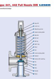
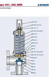
Type 441, 442 Full Nozzle DIN<br />
Conventional design<br />
Type 441, 442 Full nozzle DIN<br />
40<br />
19<br />
Cap H2<br />
Lock nut<br />
18<br />
Adjusting screw<br />
16<br />
Upper spring plate<br />
12 Spindle<br />
9 Bonnet<br />
54 Spring<br />
14<br />
Split ring<br />
55 Stud<br />
56 Nut<br />
17 Lower spring plate<br />
60 Gasket<br />
8<br />
Guide with bushing<br />
57 Pin<br />
61 Ball<br />
7 Disc<br />
5 Nozzle<br />
1 Body<br />
06/02 LWN 488.01-E
Type 441, 442 Full Nozzle DIN<br />
Conventional design<br />
Materials<br />
Item Component Type 4412 / 4422 Full nozzle DIN Type 4414 Full nozzle DIN<br />
1 Body<br />
5 Nozzle<br />
7 Disc<br />
8<br />
Guide<br />
with bushing<br />
9 Bonnet<br />
12 Spindle<br />
14 Split ring<br />
16 / 17 Spring plate<br />
18<br />
Adjusting screw<br />
with bushing<br />
19 Lock nut<br />
40 Cap H2<br />
54<br />
Spring standard<br />
Spring optional<br />
55 Stud<br />
56 Nut<br />
57 Pin<br />
60 Gasket<br />
61 Ball<br />
1.0619 1.4408<br />
SA 216 WCB<br />
SA 351 CF8M<br />
1.4404 1.4404<br />
316L<br />
316L<br />
1.4122 1.4404<br />
Hardened stainless steel<br />
316L<br />
1.0501 1.4404<br />
Carbon steel<br />
316L<br />
1.4104 tenifer –<br />
Chrome steel –<br />
0.7040, 0.7043, 1.0619<br />
1.4408 or<br />
1.4571<br />
Ductile Gr. 60-40-18,<br />
SA 216 WCB<br />
SA CF8M or<br />
SA 479 316Ti<br />
1.4021 1.4404<br />
420 316L<br />
1.4104 1.4404<br />
Chrome steel<br />
316L<br />
1.0718 1.4404<br />
12L13<br />
316L<br />
1.4104 PTFE 1.4404<br />
Chrome steel PTFE<br />
316L PTFE<br />
1.0718 1.4404<br />
Steel<br />
316L<br />
1.0718 1.4404<br />
12L13<br />
316L<br />
1.1200, 1.8159, 1.7102 1.4310<br />
Carbon steel<br />
Stainless steel<br />
1.4310 –<br />
Stainless steel –<br />
1.1181 1.4401<br />
Steel<br />
B8M<br />
1.0501 1.4401<br />
2H<br />
8M<br />
1.4310 1.4310<br />
Stainless steel<br />
Stainless steel<br />
Graphite / 1.4401 Graphite / 1.4401<br />
Graphite / 316 Graphite / 316<br />
1.3541 1.4401<br />
Hardened stainless steel 316<br />
Type 441, 442 Full nozzle DIN<br />
Please notice:<br />
– Modifications reserved by <strong>LESER</strong>.<br />
– <strong>LESER</strong> can upgrade materials without notice.<br />
– Every part can be replaced by other material acc. to customer specification.<br />
LWN 488.01-E<br />
06/03
Type 441, 442 Full nozzle DIN<br />
Balanced bellows design<br />
Type 441, 442 Full nozzle DIN<br />
40<br />
19<br />
18<br />
Cap H2<br />
Lock nut<br />
Adjusting screw<br />
16<br />
Upper spring plate<br />
9 Bonnet<br />
12 Spindle<br />
54 Spring<br />
14<br />
17<br />
Split ring<br />
Lower spring plate<br />
55 Stud<br />
56 Nut<br />
8<br />
11<br />
Guide with bushing<br />
Bonnet spacer<br />
60 Gasket<br />
22 Lift stopper<br />
16 Bellows<br />
57 Pin<br />
61 Ball<br />
7 Disc<br />
5 Nozzle<br />
1 Body<br />
06/04 LWN 488.01-E
Type 441, 442 Full nozzle DIN<br />
Balanced bellows design<br />
Materials<br />
Item Component Type 4412 / 4422 Full nozzle DIN Type 4414 Full nozzle DIN<br />
1 Body<br />
5 Nozzle<br />
7 Disc<br />
8<br />
Guide<br />
with bushing<br />
9 Bonnet<br />
11 Bonnet spacer<br />
12 Spindle<br />
14 Split ring<br />
15 Bellows<br />
16 / 17 Spring plate<br />
18<br />
Adjusting screw<br />
with bushing<br />
19 Lock nut<br />
22 Lift stopper<br />
40 Cap H2<br />
54<br />
Spring standard<br />
Spring optional<br />
55 Stud<br />
56 Nut<br />
57 Pin<br />
60 Gasket<br />
61 Ball<br />
1.0619 1.4408<br />
SA 216 WCB<br />
SA 351 CF8M<br />
1.4404 1.4404<br />
316L<br />
316L<br />
1.4122 1.4404<br />
Hardened stainless steel<br />
316L<br />
1.0501 1.4404<br />
Carbon steel<br />
316L<br />
1.4104 tenifer –<br />
Chrome steel –<br />
0.7040, 0.7043, 1.0619<br />
1.4408 or<br />
1.4571<br />
Ductile Gr. 60-40-18,<br />
SA 216 WCB<br />
SA 351 CF8M or<br />
SA 479 316Ti<br />
1.0460 1.4404<br />
Carbon steel<br />
316L<br />
1.4404 1.4404<br />
316L<br />
316L<br />
1.4104 1.4404<br />
Chrome steel<br />
316L<br />
1.4571 1.4571<br />
316Ti<br />
316Ti<br />
1.0718 1.4404<br />
12L13<br />
316L<br />
1.4104 PTFE 1.4404<br />
Chrome steel PTFE<br />
316L PTFE<br />
1.0718 1.4404<br />
Steel<br />
316L<br />
1.4404 1.4404<br />
316L<br />
316L<br />
1.0718 1.4404<br />
12L13<br />
316L<br />
1.1200, 1.8159, 1.7102 1.4310<br />
Carbon steel<br />
Stainless steel<br />
1.4310 –<br />
Stainless steel –<br />
1.1181 1.4401<br />
Steel<br />
B8M<br />
1.0501 1.4401<br />
2H<br />
8M<br />
1.4310 1.4310<br />
Stainless steel<br />
Stainless steel<br />
Graphite / 1.4401 Graphite / 1.4401<br />
Graphite / 316 Graphite / 316<br />
1.3541 1.4401<br />
Hardened stainless steel 316<br />
Type 441, 442 Full nozzle DIN<br />
Please notice:<br />
– Modifications reserved by <strong>LESER</strong>.<br />
– <strong>LESER</strong> can upgrade materials without notice.<br />
– Every part can be replaced by other material acc. to customer specification.<br />
LWN 488.01-E<br />
06/05
Type 441, 442 Full nozzle DIN<br />
How to order – Numbering system<br />
Type 441, 442 Full nozzle DIN<br />
1 2 3<br />
Article Number Set <strong>Pressure</strong> Connections<br />
1 2 3 4<br />
441 2 . 057 2<br />
Please state unit (in gauge)!<br />
Please do not exceed the pressure<br />
range defined in the spring charts.<br />
Please refer to page 06/14<br />
1<br />
2<br />
<strong>Valve</strong> Type 441, 442 Full nozzle DIN<br />
Type 441 – with closed bonnet<br />
Type 442 – with open bonnet<br />
Material code<br />
Code<br />
Body material<br />
2 1.0619 (WCB)<br />
4 1.4408 (CF8M)<br />
3<br />
<strong>Valve</strong> code<br />
Identifies valve size and body<br />
material, refer to page 06/09.<br />
4<br />
Code<br />
Lifting lever<br />
2 screwed cap H2<br />
3 plain lever H3<br />
4 packed lever H4<br />
5<br />
plain lever<br />
with open<br />
bonnet<br />
H3<br />
4412.0572<br />
Article No.<br />
5 bar g<br />
Set <strong>Pressure</strong><br />
H64<br />
Connections<br />
06/06 LWN 488.01-E
Type 441, 442 Full nozzle DIN<br />
4 5 6<br />
Options Documentation Code and Medium<br />
Type 441, 442 Full nozzle DIN<br />
Type 441, 442<br />
Full nozzle DIN<br />
• O-ring-disc<br />
Option code<br />
CR “K” J21<br />
EPDM “D” J22<br />
FKM “L” J23<br />
FFKM “C” J20<br />
• Disc 1.4404 / 316L<br />
L44<br />
• Disc 1.4404 / 316L stellited J25<br />
• Detachable lifting aid<br />
J26<br />
• Stainless steel bellows<br />
- open bonnet (Type 442) J68<br />
- closed bonnet (Type 441) J78<br />
• Elastomer bellows<br />
J79<br />
• <strong>High</strong> temperature alloy spring X01<br />
• Stainless steel spring<br />
X04<br />
• Adaptor for lift indicator H4 J39<br />
• Lift indicator<br />
J93<br />
• Test gag<br />
- cap H2 J70<br />
- packed lever H4 J69<br />
• Nozzle 316L stellited<br />
L62<br />
• Heating jacket<br />
- Couplings G 3 / 8 H29<br />
G 3 / 4 H30<br />
- Flanges DN 15 H31<br />
DN 25 H32<br />
• Drain hole G 1 / 4 J18<br />
G 1 / 2 J19<br />
• Free of oil and grease<br />
J85<br />
• Materials<br />
- NACE H01<br />
Please select requested documentation:<br />
Inspections, tests: Option code<br />
DIN EN 10204-3.2: TÜV-Nord<br />
Certificate for test pressure M33<br />
<strong>LESER</strong> Certificate for<br />
Global Application<br />
- Inspection certificate 3.1 acc.<br />
to DIN EN 10204<br />
- Declaration of conformity acc.<br />
to PED 97/23/EC<br />
Material test certificate:<br />
DIN EN 10204-3.1<br />
Part<br />
Body<br />
Nozzle<br />
Bonnet<br />
Cap / lever cover<br />
Disc<br />
Studs<br />
Nuts<br />
H03<br />
Option code<br />
H01<br />
L59<br />
L30<br />
L31<br />
L23<br />
N07<br />
N08<br />
1<br />
2<br />
1 2<br />
2 . 0<br />
Code<br />
1. ASME Section VIII<br />
2. CE / VdTUEV<br />
3. ASME Section VIII<br />
+ CE / VdTUEV<br />
Medium<br />
.1 Gases<br />
.2 Liquids<br />
.3 Steam<br />
.0 Steam / Gases / Liquids<br />
(valid only for CE / VdTUEV)<br />
Option code applies only<br />
if not standard<br />
J22 H01 L30<br />
2.0<br />
Options<br />
Documentation<br />
Code and Medium<br />
LWN 488.01-E<br />
06/07
Type 441, 442 Full nozzle DIN<br />
How to order – Article numbers<br />
Type 441, 442 Full nozzle DIN<br />
Type 441 Full nozzle<br />
Cap H2<br />
Closed bonnet<br />
Conventional design<br />
Type 441 Full nozzle<br />
Plain lever H3<br />
Closed bonnet<br />
Conventional design<br />
Type 441 Full nozzle<br />
Packed lever H4<br />
Closed bonnet<br />
Conventional design<br />
Type 442 Full nozzle<br />
Plain lever H3<br />
Open bonnet<br />
Conventional design<br />
Type 441 Full nozzle<br />
Cap H2<br />
Closed bonnet<br />
Balanced bellows design<br />
06/08 LWN 488.01-E
Type 441, 442 Full nozzle DIN<br />
How to order – Article numbers<br />
Article numbers<br />
DN I 25 40 50<br />
DN O 50 65 80<br />
Actual Orifice diameter d 0 [mm] 23 37 46<br />
Actual Orifice area A 0 [mm 2 ] 416 1075 1662<br />
Body material: 1.0619 (WCB)<br />
Bonnet H2 Art.-No. 4412. 0572 0582 0592<br />
closed H3 Art.-No. 4412. 0573 0583 0593<br />
Type 441, 442 Full nozzle DIN<br />
H4 Art.-No. 4412. 0574 0584 0594<br />
open H3 Art.-No. 4422. 0575 0585 0595<br />
Body material: 1.4408 (CF8M)<br />
Bonnet H2 Art.-No. 4422. 0952 0962 0972<br />
closed H4 Art.-No. 4422. 0954 0964 0974<br />
For sizes DN 80/3" and above please select Series 526 valves, DIN drilled or 441 Full nozzle ANSI, DIN drilled.<br />
LWN 488.01-E<br />
06/09
Type 441, 442 Full nozzle DIN<br />
Dimensions and weights<br />
Type 441, 442 Full nozzle DIN<br />
Metric Units<br />
DN I 25 40 50<br />
DN O 50 65 80<br />
Actual Orifice diameter d 0 [mm] 23 37 46<br />
Actual Orifice area A 0 [mm 2 ] 416 1075 1662<br />
Weight 9 16 22<br />
[kg] with bellows 10 17 24<br />
Center to face Inlet a 111 143,5 154<br />
[mm] Outlet b 100 115 120<br />
Height (H4) Standard H max. 345 515,5 573<br />
[mm]<br />
Bellows H max. 384 553,5 619<br />
Body material: 1.0619 (WCB)<br />
DIN Flange 1) Inlet PN 40 or 16<br />
Body material: 1.4408 (CF8M)<br />
Outlet PN 16<br />
DIN Flange 1) Inlet PN 40 or 16<br />
Outlet PN 16<br />
1) Standard flange rating. For other flange drillings and facings please refeer to page 06/14.<br />
Conventional design<br />
Balanced bellows design<br />
06/10 LWN 488.01-E
Type 441, 442 Full nozzle DIN<br />
Dimensions and weights<br />
US Units<br />
DN I 25 40 50<br />
DN O 50 65 80<br />
Actual Orifice diameter d 0 [inch] 0,91 1,46 1,81<br />
Actual Orifice area A 0 [inch 2 ] 0,644 1,667 2,576<br />
Weight 20 35 49<br />
[lbs] with bellows 21 38 52<br />
Type 441, 442 Full nozzle DIN<br />
Center to face Inlet a 4 3 / 8 5 5 / 8 6 1 / 16<br />
[inch]<br />
Outlet b 3 15 / 16 4 1 / 2 4 3 / 4<br />
Height (H4) Standard H max. 9 3 / 16 13 14 5 / 8<br />
[inch]<br />
Bellows H max. 10 11 / 16 14 16 1 / 8<br />
Body material: 1.0619 (WCB)<br />
DIN Flange 1) Inlet PN 40 or 16<br />
Body material: 1.4408 (CF8M)<br />
Outlet PN 16<br />
DIN Flange 1) Inlet PN 40 or 16<br />
Outlet PN 16<br />
1) Standard flange rating. For other flange drillings and facings please refeer to page 06/14.<br />
Conventional design<br />
Balanced bellows design<br />
LWN 488.01-E<br />
06/11
Type 441, 442 Full nozzle DIN<br />
<strong>Pressure</strong> temperature ratings<br />
Type 441, 442 Full nozzle DIN<br />
Metric Units<br />
DN I 25 40 50<br />
DN O 50 65 80<br />
Actual Orifice diameter d 0 [mm] 23 37 46<br />
Actual Orifice area A 0 [mm 2 ] 416 1075 1662<br />
Body material: 1.0619 (WCB)<br />
DIN Flange<br />
Inlet PN 40 or 16<br />
Outlet PN 16<br />
Minimum<br />
set pressure p [bar g] S/G/L 0,1 0,1 0,1<br />
Min. set pressure 1)<br />
standard bellows<br />
Min. set pressure<br />
low press. bellows<br />
Maximum<br />
set pressure<br />
Max. set pressure<br />
with special spring<br />
p [bar g] S/G/L 3 3 3<br />
p [bar g] S/G/L 0,98 1,11 1,81<br />
p [bar g] S/G/L 40 40 40<br />
p [bar g] S/G/L 40 40 40<br />
Temperature min. [°C] -85<br />
acc. to DIN EN<br />
max. [°C] +450<br />
Temperature min. [°C] -29<br />
acc. to ASME max. [°C] +427<br />
Body material: 1.4408 (CF8M)<br />
DIN Flange<br />
Minimum<br />
set pressure<br />
Inlet PN 40 or 16<br />
Outlet PN 16<br />
p [bar g] S/G/L 0,1 0,1 0,1<br />
Min. set pressure 1) p [bar g] S/G/L 3 3 3<br />
standard bellows<br />
Min. set pressure<br />
low press. bellows<br />
Maximum<br />
set pressure<br />
Max. set pressure<br />
with special spring<br />
p [bar g] S/G/L 0,98 1,11 1,81<br />
p [bar g] S/G/L 40 40 33<br />
p [bar g] S/G/L 40 40 37<br />
Temperature min. [°C] -270<br />
acc. to DIN EN<br />
max. [°C] +400<br />
Temperature min. [°C] -268<br />
acc. to ASME max. [°C] +538<br />
1) Min. set pressure standard bellows = Max. set pressure low pressure bellows.<br />
06/12 LWN 488.01-E
Type 441, 442 Full nozzle DIN<br />
<strong>Pressure</strong> temperature ratings<br />
US Units<br />
DN I 25 40 50<br />
DN O 50 65 80<br />
Actual Orifice diameter d 0<br />
[inch] 0,91 1,46 1,81<br />
Actual Orifice area A 0<br />
[inch 2 ] 0,644 1,667 2,576<br />
Body material: 1.0619 (WCB)<br />
DIN Flange<br />
Inlet PN 40 or 16<br />
Outlet PN 16<br />
Minimum<br />
set pressure p [psig] S/G/L 1,5 1,5 1,5<br />
Type 441, 442 Full nozzle DIN<br />
Min. set pressure 1)<br />
standard bellows<br />
Min. set pressure<br />
low press. bellows<br />
Maximum<br />
set pressure<br />
Max. set pressure<br />
with special spring<br />
p [psig] S/G/L 43,5 43,5 43,5<br />
p [psig] S/G/L 14 16 26<br />
p [psig] S/G/L 580 580 580<br />
p [psig] S/G/L 580 580 580<br />
Temperature min. [°F] -121<br />
acc. to DIN EN<br />
max. [°F] +842<br />
Temperature min. [°F] -20<br />
acc. to ASME max. [°F] +800<br />
Body material: 1.4408 (CF8M)<br />
DIN Flange<br />
Minimum<br />
set pressure<br />
Inlet PN 40 or 16<br />
Outlet PN 16<br />
p [psig] S/G/L 1,5 1,5 1,5<br />
Min. set pressure 1) p [psig] S/G/L 43,5 43,5 43,5<br />
standard bellows<br />
Min. set pressure<br />
low press. bellows<br />
Maximum<br />
set pressure<br />
Max. set pressure<br />
with special spring<br />
p [psig] S/G/L 14 16 26<br />
p [psig] S/G/L 580 580 479<br />
p [psig] S/G/L 580 580 537<br />
Temperature min. [°F] -454<br />
acc. to DIN EN<br />
max. [°F] +752<br />
Temperature min. [°F] -450<br />
acc. to ASME max. [°F] +1000<br />
1) Min. set pressure standard bellows = Max. set pressure low pressure bellows.<br />
LWN 488.01-E<br />
06/13
Type 441, 442 Full nozzle DIN<br />
Flange drillings and facings<br />
Type 441, 442 Full nozzle DIN<br />
Flange drillings<br />
DN I 25 40 50<br />
DN O 50 65 80<br />
Actual Orifice diameter d 0 [mm] 23 37 46<br />
Actual Orifice area A 0 [mm 2 ] 416 1075 1662<br />
Body material: 1.0619 (WCB), 1.4408 (CF8M)<br />
DIN EN 1092<br />
Inlet<br />
ASME B16.5<br />
DIN EN 1092<br />
Outlet<br />
ASME B16.5<br />
PN 10<br />
* * *<br />
PN 16<br />
* * *<br />
PN 25<br />
* * *<br />
PN 40<br />
* * *<br />
CL150 H64 H64 H64<br />
CL300 – – [H65]<br />
PN 10<br />
* * *<br />
PN 16<br />
* * *<br />
PN 25<br />
*<br />
(H15) (<br />
* )<br />
PN 40<br />
*<br />
(H15) (<br />
* )<br />
CL150 H 79 H 79 H 79<br />
CL300 – – –<br />
Flange facings<br />
Indication Standard Nozzle Outlet Remark<br />
General<br />
Flange undrilled – H38 H39<br />
Linde-V-Nut, Form V48 Linde Standard 420-08<br />
– J08 Groove: Rz 16<br />
Linde-V-Nut, Form V48A LWN 313.36<br />
– J06 Groove: Rz 4, e.g. with hydrogen<br />
Lens seal form L<br />
DIN 2696<br />
(without sealing lens)<br />
LWN 313.35<br />
L57<br />
J12<br />
Acc. to DIN EN<br />
Flange facing<br />
DIN EN 1092<br />
Inlet<br />
Outlet<br />
(new)<br />
DIN 2526<br />
(old)<br />
(see also LWN 313.40) PN 10 – PN 40 PN 10 – PN 40<br />
Remark<br />
Rz-data according to<br />
DIN EN 1092 in µm<br />
Type C<br />
Type B1<br />
Raised face<br />
Type D<br />
* *<br />
Facing: Rz = 12,5 – 50<br />
Type B2 Type E – L38 Facing: Rz = 3,2 – 12,5<br />
Tongue face C 1) Tongue face F L56 H92<br />
Groove face D 1) Groove face N L55 H91<br />
Male face E Male face V13 I90 H98<br />
Female face F Female face R13 I91 H99<br />
O-ring male face G Male face V14 I93 J02<br />
O-ring female face H Female face R14 I92 J04<br />
Acc. to ASME B16.5<br />
Smooth finish 2) Serrated finish RTJ-groove<br />
Body material Inlet Outlet Inlet Outlet Inlet Outlet Inlet Outlet<br />
Option code Option code RTJ-Class Option code RTJ-Class Option code<br />
1.0619, 1.4408 all all L52 L53<br />
* *<br />
CL150, CL300 L58 CL150 H63<br />
Steel flanges only<br />
1)<br />
According to DIN EN 1092 groove depths and tongue heights increased compared to the formerly valid DIN (refer to LWN 313.40).<br />
<strong>LESER</strong> manufactures the groove at flanged valves by milling. If a customer demands a turned surface in the soil of the groove according to DIN 2512 and/or<br />
DIN EN 1092-1 an additional option code is necessary: “S01: bottom of the groove drilled”. Groove and tongue for PN160 flanges refer to DIN 2512/LWN 313.32.<br />
2)<br />
Smooth finish is not defined in the effective standards. For <strong>LESER</strong>‘s definition for smooth finish see page 00/07.<br />
For signs and symbols refer to page 00/07<br />
Note: Flange drillings and facings meet always the requirements of mentioned flange standards. Flange thickness and outer diameter may vary from flange standard.<br />
06/14 LWN 488.01-E
Type 441, 442 Full nozzle DIN<br />
Order information – Spare parts<br />
Spare parts<br />
DN I<br />
25 40 50<br />
DN O 50 65 80<br />
Actual Orifice diameter d 0 [mm] 23 37 46<br />
Actual Orifice area A 0 [mm 2 ] 416 1075 1662<br />
Disc (Item 7): Metal to metal seat<br />
Material-No. / Art.-No.<br />
Disc 1.4122 200.9739.9000 200.9939.9000 200.8739.9000<br />
detachable lifting aid<br />
1.4404 200.9749.9000 200.9949.9000 200.8749.9000<br />
Disc (Item 7): Soft seal<br />
Material-No. / Art.-No.<br />
Disc CR “K” 200.5049.9051 200.5249.9051 200.5349.9051<br />
Disc (Item 7.4): Soft seal<br />
EPDM “D” 200.5049.9041 200.5249.9041 200.5349.9041<br />
FKM “L” 200.5049.9071 200.5249.9071 200.5349.9071<br />
FFKM “C” 200.5049.9091 502.0408.3591 502.0503.3591<br />
Material-No. / Art.-No.<br />
O-ring CR “K” 502.0249.3551 502.0408.3551 502.0503.3551<br />
Bellows (Item 15) 1.4571<br />
EPDM “D” 502.0249.3541 502.0408.3541 502.0503.3541<br />
FKM “L” 502.0249.3571 502.0408.3571 502.0503.3571<br />
FFKM “C” 502.0249.3591 502.0408.3591 502.0503.3591<br />
Material-No. / Art.-No.<br />
Standard bellows 400.0949.0000 400.1149.0000 400.1249.0000<br />
Conversion kit standard 1) 5021.1041 5021.1043 5021.1044<br />
Low pressure bellows 400.0949.0021 400.1149.0021 400.1249.0021<br />
Conversion kit low pressure 1)<br />
Gasket – body / bonnet (Item 60)<br />
please specify in writing<br />
Material-No. / Art.-No.<br />
Gasket Graphite + 1.4401 500.0607.0000 500.1007.0000 500.1207.0000<br />
Option code L68 Gylon (filled PTFE) 500.0605.0000 500.1005.0000 500.1205.0000<br />
Ball (Item 61)<br />
Material-No. / Art.-No.<br />
Ball Ball Ø [mm] 6 9 9<br />
Split ring (Item 14)<br />
1.4404 510.0104.0000 510.0204.0000 510.0204.0000<br />
Material-No. / Art.-No.<br />
Split ring Spindle Ø [mm] 12 16 16<br />
Pin (Item 57)<br />
1.4404 251.0149.0000 251.0249.0000 251.0249.0000<br />
Material-No. / Art.-No.<br />
Pin 1.4310 480.0505.0000 480.0705.0000 480.0705.0000<br />
Type 441, 442 Full nozzle DIN<br />
1)<br />
For pressure range see page 06/12 – 06/13.<br />
A conversion kit contains the following components:<br />
Item Component No.<br />
8 Guide 1<br />
11 Bonnet spacer 1<br />
12 Spindle 1<br />
15 Bellows 1<br />
55 Stud 4<br />
60 Gasket 2, 3 depends on valve size<br />
Installation instruction LWN 037.05 1<br />
Refer to page 06/04<br />
LWN 488.01-E<br />
06/15
Type 441, 442 Full nozzle DIN<br />
Available Options<br />
For further information refer to<br />
“Accessories and Options”, page 99/01<br />
Type 441, 442 Full nozzle DIN<br />
Heating jacket<br />
H29, H30: Couplings G 3 / 8 , G<br />
3/ 4<br />
H31, H32: Flanges DN 15, DN 25<br />
Drain hole<br />
Open bonnet<br />
J18: G 1 / 4<br />
See Art.-No.<br />
J19: G 1 / 2<br />
O-ring-disc<br />
J20: FFKM “C”<br />
J21: CR “K”<br />
J22: EPDM “D”<br />
J23: FKM “L”<br />
Disc with inserted sealing plate<br />
J44: PTFE-FDA<br />
J48: PCTFE<br />
J49: SP<br />
Stainless steel bellows<br />
J68: Open bonnet<br />
J78: Closed bonnet<br />
Conversion kit for<br />
stainless steel bellows<br />
See Art.-No. page 06/15<br />
Screwed cap H2<br />
H2<br />
Plain lever H3<br />
H3<br />
Packed lever H4<br />
H4<br />
Test gag<br />
J69: H4<br />
J70: H2<br />
Lift indicator<br />
J39: Adaptor H4<br />
J93: Lift indicator<br />
O-ring-damper H2<br />
J65<br />
O-ring-damper H4<br />
J66<br />
06/16 LWN 488.01-E
Type 441, 442 Full nozzle DIN<br />
Approvals<br />
Approvals<br />
DN I 25 40 50<br />
DN O 50 65 80<br />
Actual Orifice diameter d 0 [mm] 23 37 46<br />
Actual Orifice area A 0 [mm 2 ] 416 1075 1662<br />
Europe<br />
Coefficient of discharge K dr<br />
DIN EN ISO 4126-1 Approval No. 072020111Z0008/0/08-2<br />
S/G 0,7<br />
L 0,45<br />
Germany<br />
Coefficient of discharge α w<br />
AD 2000-Merkblatt A2 Approval No. TÜV SV 576<br />
S/G 0,7<br />
L 0,45<br />
United States<br />
Coefficient of discharge K<br />
ASME Sec. VIII Approval No. M37044<br />
S/G 0,699<br />
Approval No.<br />
M37055<br />
L 0,521<br />
Canada<br />
Coefficient of discharge K<br />
Canada: CRN Approval No. OG1182.9C<br />
S/G 0,699<br />
L 0,521<br />
China<br />
Coefficient of discharge α w<br />
CSBQTS<br />
Approval No.<br />
S/G 0,7<br />
L 0,45<br />
Russia<br />
Coefficient of discharge α w<br />
on request<br />
Classification societies<br />
on request<br />
Type 441, 442 Full nozzle DIN<br />
LWN 488.01-E<br />
06/17
Type 441, 442 Full nozzle DIN<br />
Capacities – Steam<br />
Type 441, 442 Full nozzle DIN<br />
Capacities for saturated steam according to AD 2000-Merkblatt A2,<br />
based on set pressure plus 10 % overpressure.<br />
Capacities at 1 bar (14,5 psig) and below are based on 0,1 bar (1,45 psig)<br />
overpressure.<br />
Metric Units<br />
AD 2000-Merkblatt A2 [kg/h]<br />
DN I<br />
25 40 50<br />
DN O 40 65 80<br />
Actual Orifice diameter d 0 [mm] 23 37 46<br />
Actual Orifice area A 0 [mm 2 ] 416 1075 1662<br />
LEO S/G * ) [inch 2 ] 0,462 1,195 1,847<br />
Set pressure [bar]<br />
Capacities [kg/h]<br />
0,1 0 0 0<br />
0,2 140 363 561<br />
0,5 224 579 895<br />
1 326 843 1302<br />
2 519 1343 2075<br />
3 699 1808 2794<br />
4 871 2254 3485<br />
5 1043 2699 4172<br />
6 1214 3142 4856<br />
7 1381 3574 5525<br />
8 1551 4014 6205<br />
9 1721 4454 6884<br />
10 1891 4893 7562<br />
12 2230 5770 8919<br />
14 2562 6629 10247<br />
16 2900 7505 11600<br />
18 3239 8382 12955<br />
20 3578 9260 14312<br />
22 3907 10111 15629<br />
24 4247 10991 16988<br />
26 4588 11873 18351<br />
28 4930 12757 19718<br />
30 5272 13644 21089<br />
32 5616 14534 22465<br />
34 5945 15384 23779<br />
36 6290 16278 25160<br />
38 6637 17175 26547<br />
40 6985 18076 27939<br />
Capacities for saturated steam according to ASME Section VIII (UV),<br />
based on set pressure plus 10% overpressure.<br />
Capacities at 2,07 bar (30 psig) and below are based on 0,207 bar (3 psig)<br />
overpressure.<br />
US Units<br />
ASME Section VIII [lb/h]<br />
DN I<br />
25 40 50<br />
DN O 40 65 80<br />
Actual Orifice diameter d 0 [inch] 0,91 1,46 1,81<br />
Actual Orifice area A 0 [inch 2 ] 0,644 1,667 2,576<br />
LEO S/G * ) [inch 2 ] 0,462 1,195 1,847<br />
Set pressure [psig]<br />
Capacities [lb/h]<br />
15 757 1959 3028<br />
20 873 2259 3492<br />
30 1105 2859 4419<br />
40 1360 3519 5439<br />
50 1615 4179 6459<br />
60 1870 4839 7479<br />
70 2125 5499 8499<br />
80 2380 6159 9519<br />
90 2635 6819 10539<br />
100 2890 7479 11559<br />
120 3400 8799 13600<br />
140 3910 10118 15640<br />
160 4420 11438 17680<br />
180 4930 12758 19720<br />
200 5440 14078 21760<br />
220 5950 15398 23800<br />
240 6460 16718 25840<br />
260 6970 18038 27880<br />
280 7480 19358 29920<br />
300 7990 20677 31960<br />
320 8500 21997 34000<br />
340 9010 23317 36040<br />
360 9520 24637 38080<br />
380 10030 25957 40120<br />
400 10540 27277 42161<br />
420 11050 28597 44201<br />
440 11560 29917 46241<br />
460 12070 31236 48281<br />
480 12580 32556 50321<br />
500 13090 33876 52361<br />
550 14365 37176 57461<br />
580 15130 39156 60521<br />
* ) LEO S/G<br />
= <strong>LESER</strong> Effective Orifice steam/gas please refer to page 00/11<br />
How to use capacity-sheets refer to page 00/09<br />
06/18 LWN 488.01-E
Type 441, 442 Full nozzle DIN<br />
Capacities – Air<br />
Capacities for air according to AD 2000-Merkblatt A2,<br />
based on set pressure plus 10 % overpressure at 0 °C and 1013 mbar.<br />
Capacities at 1 bar (14,5 psig) and below are based on<br />
0,1 bar (1,45 psig) overpressure.<br />
Metric Units<br />
AD 2000-Merkblatt A2 [m n3<br />
/h]<br />
DN I<br />
25 40 50<br />
DN O 40 65 80<br />
Actual Orifice diameter d 0<br />
[mm] 23 37 46<br />
Actual Orifice area A 0 [mm 2 ] 416 1075 1662<br />
LEO S/G * ) [inch 2 ] 0,462 1,195 1,847<br />
Set pressure [bar]<br />
Capacities [m n3 /h]<br />
0,1 0 0 0<br />
0,2 162 420 649<br />
0,5 263 680 1051<br />
1 388 1004 1552<br />
2 627 1622 2507<br />
3 854 2209 3414<br />
4 1071 2773 4286<br />
5 1289 3337 5157<br />
6 1507 3900 6029<br />
7 1725 4464 6900<br />
8 1943 5028 7771<br />
9 2161 5592 8643<br />
10 2379 6155 9514<br />
12 2814 7283 11257<br />
14 3250 8411 13000<br />
16 3686 9538 14743<br />
18 4121 10666 16486<br />
20 4557 11793 18228<br />
22 4993 12921 19971<br />
24 5429 14048 21714<br />
26 5864 15176 23457<br />
28 6300 16304 25200<br />
30 6736 17431 26942<br />
32 7171 18559 28685<br />
34 7607 19686 30428<br />
36 8043 20814 32171<br />
38 8478 21941 33914<br />
40 8914 23069 35657<br />
Capacities for air according to ASME Section VIII (UV),<br />
based on set pressure plus 10% overpressure at 16 °C (60°F).<br />
Capacities at 2,07 bar (30 psig) and below are based on<br />
0,207 bar (3 psig) overpressure.<br />
US Units<br />
ASME Section VIII [S.C.F.M]<br />
DN I<br />
25 40 50<br />
DN O 40 65 80<br />
Actual Orifice diameter d 0<br />
[inch] 0,91 1,46 1,81<br />
Actual Orifice area A 0 [inch 2 ] 0,644 1,667 2,576<br />
LEO S/G * ) [inch 2 ] 0,462 1,195 1,847<br />
Set pressure [psig]<br />
Capacities [S.C.F.M.]<br />
15 270 698 1079<br />
20 311 805 1244<br />
30 394 1019 1574<br />
40 484 1254 1938<br />
50 575 1489 2301<br />
60 666 1724 2664<br />
70 757 1959 3028<br />
80 848 2194 3391<br />
90 939 2430 3754<br />
100 1029 2665 4118<br />
120 1211 3135 4845<br />
140 1393 3605 5571<br />
160 1574 4076 6298<br />
180 1756 4546 7025<br />
200 1938 5016 7751<br />
220 2120 5486 8478<br />
240 2301 5957 9205<br />
260 2483 6427 9932<br />
280 2665 6897 10658<br />
300 2846 7368 11385<br />
320 3028 7838 12112<br />
340 3210 8308 12839<br />
360 3391 8778 13565<br />
380 3573 9249 14292<br />
400 3755 9719 15019<br />
420 3936 10189 15745<br />
440 4118 10660 16472<br />
460 4300 11130 17199<br />
480 4481 11600 17926<br />
500 4663 12070 18652<br />
550 5117 13246 20469<br />
580 5390 13952 21559<br />
Type 441, 442 Full nozzle DIN<br />
* ) LEO S/G<br />
= <strong>LESER</strong> Effective Orifice steam/gas please refer to page 00/11<br />
How to use capacity-sheets refer to page 00/09<br />
LWN 488.01-E<br />
06/19
Type 441, 442 Full nozzle DIN<br />
Capacities – Water<br />
Type 441, 442 Full nozzle DIN<br />
Capacities for water according to AD 2000-Merkblatt A2,<br />
based on set pressure plus 10 % overpressure at 20 °C (68 °F).<br />
Capacities at 1 bar (14,5 psig) and below are based<br />
on 0,1 bar (1,45 psig) overpressure.<br />
Metric Units<br />
AD 2000-Merkblatt A2 [10 3 kg/h]<br />
DN I<br />
25 40 50<br />
DN O 40 65 80<br />
Actual Orifice diameter d 0 [mm] 23 37 46<br />
Actual Orifice area A 0 [mm 2 ] 416 1075 1662<br />
Set pressure [bar]<br />
LEO L * ) [inch 2 ] 0,516 1,336 2,062<br />
Capacities [10 3 kg/h]<br />
0,1 4,25 11,0 17,0<br />
0,2 5,21 13,5 20,8<br />
0,5 7,37 19,1 29,5<br />
1 9,97 25,8 39,9<br />
2 14,1 36,5 56,4<br />
3 17,3 44,7 69,1<br />
4 19,9 51,6 79,8<br />
5 22,3 57,7 89,2<br />
6 24,4 63,2 97,7<br />
7 26,4 68,3 106<br />
8 28,2 73,0 113<br />
9 29,9 77,4 120<br />
10 31,5 81,6 126<br />
12 34,6 89,4 138<br />
14 37,3 96,6 149<br />
16 39,3 103 160<br />
18 42,3 110 169<br />
20 44,6 115 178<br />
22 46,8 121 187<br />
24 48,9 126 195<br />
26 50,9 132 203<br />
28 52,8 137 211<br />
30 54,6 141 219<br />
32 56,4 146 226<br />
34 58,2 151 233<br />
36 59,8 155 239<br />
38 61,5 159 246<br />
40 63,1 163 252<br />
Capacities for water according to ASME Section VIII (UV),<br />
based on set pressure plus 10 % overpressure at 21 °C (70 °F).<br />
Capacities at 2,07 bar (30 psig) and below are based on<br />
0,207 bar (3 psig) overpressure.<br />
US Units<br />
ASME Section VIII [US-G.P.M]<br />
DN I<br />
25 40 50<br />
DN O 40 65 80<br />
Actual Orifice diameter d 0 [inch] 0,91 1,46 1,81<br />
Actual Orifice area A 0 [inch 2 ] 0,644 1,667 2,576<br />
Set pressure [psig]<br />
LEO L * ) [inch 2 ] 0,516 1,336 2,062<br />
Capacities [US-G.P.M.]<br />
15 54,0 140 216<br />
20 61,1 158 244<br />
30 73,1 189 293<br />
40 84,5 219 338<br />
50 94,4 244 378<br />
60 103 268 414<br />
70 112 289 447<br />
80 119 309 478<br />
90 127 328 507<br />
100 134 346 534<br />
120 146 379 585<br />
140 158 409 632<br />
160 169 437 676<br />
180 179 464 717<br />
200 189 489 755<br />
220 198 513 792<br />
240 207 535 827<br />
260 215 557 861<br />
280 223 578 894<br />
300 231 599 925<br />
320 239 618 955<br />
340 246 637 985<br />
360 253 656 1013<br />
380 260 674 1041<br />
400 267 691 1068<br />
420 274 708 1095<br />
440 280 725 1120<br />
460 286 741 1146<br />
480 293 757 1170<br />
500 299 773 1194<br />
550 313 811 1253<br />
580 322 832 1286<br />
* ) LEO L<br />
= <strong>LESER</strong> Effective Orifice liquids please refer to page 00/12<br />
How to use capacity-sheets refer to page 00/09<br />
06/20 LWN 488.01-E
Type 441, 442 Full nozzle DIN<br />
Determination of coefficent of discharge<br />
in case of lift restriction or back pressure<br />
Diagram for evaluation of ratio of lift / flow diameter (h/d 0 )<br />
in reference to the coefficient of discharge (K dr /α w )<br />
0,8<br />
0,7<br />
0,6<br />
K dr = α w = f (h/d 0 )<br />
"S/G"<br />
h = Lift [mm]<br />
d 0 = Flow diameter [mm] of selected safety<br />
valve, refer to table article numbers<br />
h/d0 = Ratio of lift / flow diameter<br />
p a0 = Back pressure [bar a]<br />
p 0 = Set pressure [bar a]<br />
p a0 / p 0 = Ratio of back pressure / set pressure<br />
K dr = Coefficient of discharge<br />
acc. to DIN EN ISO 4126-1<br />
α w = Coefficient of discharge<br />
acc. to AD 2000-Merkblatt A2<br />
K b = Back pressure correction factor<br />
acc. to API 520 topic 3.3<br />
Type 441, 442 Full nozzle DIN<br />
0,5<br />
Coefficient of discharge K dr / αw<br />
0,4<br />
0,3<br />
0,2<br />
0,1<br />
0<br />
0<br />
0,1 0,2<br />
"L"<br />
0,3<br />
Ratio of lift / flow diameter h / d 0<br />
Diagram for evaluation of coefficient of discharge (K dr /α w ) or K b<br />
in reference to the ratio of back pressure / set pressure (p a0 /p 0 )<br />
0,8<br />
K dr = α w = f (p a0 /p 0 ) and K b = f (p a0 /p 0 )<br />
0,7<br />
1,0<br />
0,6<br />
0,9<br />
0,8<br />
0,5<br />
0,7<br />
Coefficient of discharge K dr / αw<br />
0,4<br />
0,3<br />
0,2<br />
0,1<br />
0<br />
0,2<br />
0,3<br />
0,4<br />
0,5 0,6 0,7<br />
0,8<br />
0,91<br />
0,6<br />
0,5<br />
0,4<br />
0,3<br />
0,2<br />
0,1<br />
0<br />
Back pressure correction factor K b<br />
Ratio of back pressure / set pressure p a0 / p 0<br />
How to use please refer to page 00/08<br />
LWN 488.01-E<br />
06/21
Type 441, 442 Full nozzle DIN<br />
Type 441, 442 Full nozzle DIN<br />
06/22 LWN 488.01-E
Type<br />
Type 442 Full nozzle ANSI<br />
Plain lever H3<br />
Open bonnet<br />
Conventional design<br />
441, 442<br />
Full nozzle ANSI<br />
Type 441 Full nozzle ANSI<br />
Packed lever H4<br />
Closed bonnet<br />
Conventional design<br />
Flanged <strong>Safety</strong> Relief <strong>Valve</strong>s<br />
– spring loaded<br />
Contents<br />
Chapter/Page<br />
Materials<br />
• Conventional design 07/02<br />
• Balanced bellows design 07/04<br />
How to order<br />
• Numbering system 07/06<br />
• Article numbers 07/08<br />
Dimensions and weights<br />
• Metric Units 07/10<br />
• US Units 07/11<br />
<strong>Pressure</strong> temperature ratings<br />
• Metric Units 07/12<br />
• US Units 07/13<br />
Flange drillings and facings 07/14<br />
Order information – Spare parts 07/15<br />
Available options 07/16<br />
Approvals 07/17<br />
Capacities<br />
• Steam [Metric Units + US Units] 07/18<br />
• Air [Metric Units + US Units] 07/19<br />
• Water [Metric Units + US Units] 07/20<br />
Determination of coefficient 07/21<br />
of discharge K dr /α w<br />
Type 441, 442 Full nozzle ANSI<br />
LWN 488.01-E<br />
07/01
Type 441, 442 Full nozzle ANSI<br />
Conventional design<br />
40<br />
19<br />
Cap H2<br />
Lock nut<br />
Type 441, 442 Full nozzle ANSI<br />
18<br />
16<br />
Adjusting screw<br />
Upper spring plate<br />
12 Spindle<br />
9 Bonnet<br />
54 Spring<br />
14<br />
Split ring<br />
55 Stud<br />
56 Nut<br />
17 Lower spring plate<br />
60 Gasket<br />
8<br />
Guide with bushing<br />
57 Pin<br />
61 Ball<br />
7 Disc<br />
5 Nozzle<br />
1 Body<br />
07/02 LWN 488.01-E
Type 441, 442 Full nozzle ANSI<br />
Conventional design<br />
Materials<br />
Item Component Type 4412 / 4422 Full nozzle ANSI Type 4414 Full nozzle ANSI<br />
1 Body<br />
5 Nozzle<br />
7 Disc<br />
8<br />
Guide<br />
with bushing<br />
9 Bonnet<br />
12 Spindle<br />
14 Split ring<br />
16 / 17 Spring plate<br />
18<br />
Adjusting screw<br />
with bushing<br />
19 Lock nut<br />
40 Cap H2<br />
54<br />
Spring standard<br />
Spring optional<br />
55 Stud<br />
56 Nut<br />
57 Pin<br />
60 Gasket<br />
61 Ball<br />
1.0619 1.4408<br />
SA 216 WCB<br />
SA 351 CF8M<br />
1.4404 1.4404<br />
316L<br />
316L<br />
1.4122 1.4404<br />
Hardened stainless steel<br />
316L<br />
1.0501 1.4404<br />
Carbon steel<br />
316L<br />
1.4104 tenifer –<br />
Chrome steel –<br />
0.7040, 0.7043, 1.0619<br />
1.4408 or<br />
1.4571<br />
Ductile Gr. 60-40-18,<br />
SA 216 WCB<br />
SA CF8M or<br />
SA 479 316Ti<br />
1.4021 1.4404<br />
420 316L<br />
1.4104 1.4404<br />
Chrome steel<br />
316L<br />
1.0718 1.4404<br />
12L13<br />
316L<br />
1.4104 PTFE 1.4404<br />
Chrome steel PTFE<br />
316L PTFE<br />
1.0718 1.4404<br />
Steel<br />
316L<br />
1.0718 1.4404<br />
12L13<br />
316L<br />
1.1200, 1.8159, 1.7102 1.4310<br />
Carbon steel<br />
Stainless steel<br />
1.4310 –<br />
Stainless steel –<br />
1.1181 1.4401<br />
Steel<br />
B8M<br />
1.0501 1.4401<br />
2H<br />
8M<br />
1.4310 1.4310<br />
Stainless steel<br />
Stainless steel<br />
Graphite / 1.4401 Graphite / 1.4401<br />
Graphite / 316 Graphite / 316<br />
1.3541 1.4401<br />
Hardened stainless steel 316<br />
Type 441, 442 Full nozzle ANSI<br />
Please notice:<br />
– Modifications reserved by <strong>LESER</strong>.<br />
– <strong>LESER</strong> can upgrade materials without notice.<br />
– Every part can be replaced by other material acc. to customer specification.<br />
LWN 488.01-E<br />
07/03
Type 441, 442 Full nozzle ANSI<br />
Balanced bellows design<br />
40<br />
Cap H2<br />
19<br />
18<br />
Lock nut<br />
Adjusting screw<br />
16<br />
Upper spring plate<br />
Type 441, 442 Full nozzle ANSI<br />
9 Bonnet<br />
12 Spindle<br />
54 Spring<br />
14<br />
17<br />
Split ring<br />
Lower spring plate<br />
55 Stud<br />
56 Nut<br />
8<br />
11<br />
Guide with bushing<br />
Bonnet spacer<br />
60 Gasket<br />
22 Lift stopper<br />
16 Bellows<br />
57 Pin<br />
61 Ball<br />
7 Disc<br />
5 Nozzle<br />
1 Body<br />
07/04 LWN 488.01-E
Type 441, 442 Full nozzle ANSI<br />
Balanced bellows design<br />
Materials<br />
Item Component Type 4412 / 4422 Full nozzle ANSI Type 4414 Full nozzle ANSI<br />
1 Body<br />
5 Nozzle<br />
7 Disc<br />
8<br />
Guide<br />
with bushing<br />
9 Bonnet<br />
11 Bonnet spacer<br />
12 Spindle<br />
14 Split ring<br />
15 Bellows<br />
16 / 17 Spring plate<br />
18<br />
Adjusting screw<br />
with bushing<br />
19 Lock nut<br />
22 Lift stopper<br />
40 Cap H2<br />
54<br />
Spring standard<br />
Spring optional<br />
55 Stud<br />
56 Nut<br />
57 Pin<br />
60 Gasket<br />
61 Ball<br />
1.0619 1.4408<br />
SA 216 WCB<br />
SA 351 CF8M<br />
1.4404 1.4404<br />
316L<br />
316L<br />
1.4122 1.4404<br />
Hardened stainless steel<br />
316L<br />
1.0501/0.7040 1.4404<br />
Chrome or carbon steel<br />
316L<br />
1.4104 tenifer –<br />
Chrome steel –<br />
0.7040, 0.7043, 1.0619<br />
1.4408 or<br />
1.4571<br />
Ductile Gr. 60-40-18,<br />
SA 216 WCB<br />
SA 351 CF8M or<br />
SA 479 316Ti<br />
1.0460 1.4404<br />
Carbon steel<br />
316L<br />
1.4404 1.4404<br />
316L<br />
316L<br />
1.4104 1.4404<br />
Chrome steel<br />
316L<br />
1.4571 1.4571<br />
316 Ti 316 Ti<br />
1.0718 1.4404<br />
Steel<br />
316L<br />
1.4104 PTFE 1.4404 PTFE<br />
Chrome steel PTFE<br />
316L PTFE<br />
1.0718 1.4404<br />
Steel<br />
316L<br />
1.4404 1.4404<br />
316L<br />
316L<br />
1.0718 1.4404<br />
12L13<br />
316L<br />
1.1200, 1.8159, 1.7102 1.4310<br />
Carbon steel<br />
Stainless steel<br />
1.4310 –<br />
Stainless steel –<br />
1.1181 1.4401<br />
Steel<br />
B8M<br />
1.0501 1.4401<br />
2H<br />
8M<br />
1.4310 1.4310<br />
Stainless steel<br />
Stainless steel<br />
Graphite / 1.4401 Graphite / 1.4401<br />
Graphite / 316 Graphite / 316<br />
1.3541 1.4401<br />
Hardened stainless steel 316<br />
Type 441, 442 Full nozzle ANSI<br />
Please notice:<br />
– Modifications reserved by <strong>LESER</strong>.<br />
– <strong>LESER</strong> can upgrade materials without notice.<br />
– Every part can be replaced by other material acc. to customer specification.<br />
LWN 488.01-E<br />
07/05
Type 441, 442 Full nozzle ANSI<br />
How to order – Numbering system<br />
1 2 3<br />
Article Number Set <strong>Pressure</strong> Connections<br />
Type 441, 442 Full nozzle ANSI<br />
1<br />
2<br />
1 2<br />
3 4<br />
441 2 . 128 2<br />
<strong>Valve</strong> Type 441, 442<br />
Full nozzle ANSI<br />
Type 441 – with closed bonnet<br />
Type 442 – with open bonnet<br />
Code<br />
Body material<br />
Please state unit (in gauge)!<br />
Please do not exceed the pressure<br />
range defined in the spring charts.<br />
Please refer to page 07/14<br />
2 1.0619 (WCB)<br />
4 1.4408 (CF8M)<br />
3<br />
<strong>Valve</strong> code<br />
Identifies valve size and body<br />
material, refer to page 07/09.<br />
4<br />
Code<br />
Lifting lever<br />
2 screwed cap H2<br />
3 plain lever H3<br />
4 packed lever H4<br />
5<br />
plain lever<br />
with open<br />
bonnet<br />
H3<br />
4412.1282<br />
Article No.<br />
5 bar g<br />
Set <strong>Pressure</strong><br />
H64<br />
Connections<br />
07/06 LWN 488.01-E
Type 441, 442 Full nozzle ANSI<br />
4 5 6<br />
Options Documentation Code and Medium<br />
Type 441, 442<br />
Full nozzle ANSI<br />
• O-ring-disc<br />
Option code<br />
CR “K” J21<br />
EPDM “D” J22<br />
FKM “L” J23<br />
FFKM “C” J20<br />
• Disc 1.4404 / 316L<br />
L44<br />
• Disc 1.4404 / 316L stellited J25<br />
• Detachable lifting aid<br />
J26<br />
• Stainless steel bellows<br />
- open bonnet (Type 442) J68<br />
- closed bonnet (Type 441) J78<br />
• Elastomer bellows<br />
J79<br />
• <strong>High</strong> temperature alloy spring X01<br />
• Stainless steel spring<br />
X04<br />
• Adaptor for lift indicator H4 J39<br />
• Lift indicator<br />
J93<br />
• Test gag<br />
- cap H2 J70<br />
- packed lever H4 J69<br />
• Nozzle 316L stellited<br />
L62<br />
• Heating jacket<br />
- Couplings G 3 / 8 H29<br />
G 3 / 4 H30<br />
- Flanges DN 15 H31<br />
DN 25 H32<br />
• Drain hole G 1 / 4 J18<br />
G 1 / 2 J19<br />
• Free of oil and grease<br />
J85<br />
• Materials<br />
- NACE H01<br />
Please select requested documentation:<br />
Inspections, tests: Option code<br />
DIN EN 10204-3.2: TÜV-Nord<br />
Certificate for test pressure M33<br />
<strong>LESER</strong> Certificate for<br />
Global Application<br />
- Inspection certificate 3.1 acc.<br />
to DIN EN 10204<br />
- Declaration of conformity acc.<br />
to PED 97/23/EC<br />
Material test certificate:<br />
DIN EN 10204-3.1<br />
Part<br />
Body<br />
Nozzle<br />
Bonnet<br />
Cap / lever cover<br />
Disc<br />
Studs<br />
Nuts<br />
H03<br />
Option code<br />
H01<br />
L59<br />
L30<br />
L31<br />
L23<br />
N07<br />
N08<br />
1<br />
2<br />
1 2<br />
2 . 0<br />
Code<br />
1. ASME Section VIII<br />
2. CE / VdTUEV<br />
3. ASME Section VIII<br />
+ CE / VdTUEV<br />
Medium<br />
.1 Gases<br />
.2 Liquids<br />
.3 Steam<br />
.0 Steam / Gases / Liquids<br />
(valid only for CE / VdTUEV)<br />
Type 441, 442 Full nozzle ANSI<br />
Option code applies only<br />
if not standard<br />
J22 H01 L30<br />
2.0<br />
Options<br />
Documentation<br />
Code and Medium<br />
LWN 488.01-E<br />
07/07
Type 441, 442 Full nozzle ANSI<br />
How to order – Article numbers<br />
Type 441, 442 Full nozzle ANSI<br />
Type 441 Full nozzle<br />
Cap H2<br />
Closed bonnet<br />
Conventional design<br />
Type 441 Full nozzle<br />
Plain lever H3<br />
Closed bonnet<br />
Conventional design<br />
Type 441 Full nozzle<br />
Packed lever H4<br />
Closed bonnet<br />
Conventional design<br />
Type 442 Full nozzle<br />
Plain lever H3<br />
Open bonnet<br />
Conventional design<br />
Type 441 Full nozzle<br />
Cap H2<br />
Closed bonnet<br />
Balanced bellows design<br />
07/08 LWN 488.01-E
Type 441, 442 Full nozzle ANSI<br />
How to order – Article numbers<br />
Article numbers<br />
<strong>Valve</strong> size 1" x 2" 1 1 / 2 " x 2" 1 1 / 2 " x 2 1 / 2 " 2" x 3" 3" x 4" 4" x 6"<br />
Actual Orifice diameter d 0 [mm] 23 29 37 46 60 92<br />
Actual Orifice area A 0 [mm 2 ] 416 661 1075 1662 2827 6648<br />
Body material: 1.0619 (WCB)<br />
Bonnet H2 Art.-No. 4412. 1282 1292 1302 1312 1322 1332<br />
closed H3 Art.-No. 4412. 1283 1293 1303 1313 1323 1333<br />
H4 Art.-No. 4412. 1284 1294 1304 1314 1324 1334<br />
open H3 Art.-No. 4422. 1285 1295 1305 1315 1325 1335<br />
Body material: 1.4408 (CF8M)<br />
Bonnet H2 Art.-No. 4414. 5682 – 5702 5712 5722 5732<br />
closed H4 Art.-No. 4414. 5684 – 5704 5714 5724 5734<br />
Type 441, 442 Full nozzle ANSI<br />
LWN 488.01-E<br />
07/09
Type 441, 442 Full nozzle ANSI<br />
Dimensions and weights<br />
Metric Units<br />
<strong>Valve</strong> size 1" x 2" 1 1 / 2 " x 2" 1 1 / 2 " x 2 1 / 2 " 2" x 3" 3" x 4" 4" x 6"<br />
Actual Orifice diameter d 0 [mm] 23 29 37 46 60 92<br />
Actual Orifice area A 0 [inch 2 ] 416 661 1075 1662 2827 6648<br />
Weight 10 13 16 22 33 75<br />
[lbs] with bellows 11 14 17 24 37 83<br />
Center to face Inlet a 109 129,5 129,5 141 163 188<br />
[mm] Outlet b 114 121 121 124 165 229<br />
Type 441, 442 Full nozzle ANSI<br />
Height (H4) Standard H max. 339 455 496 556 685 844<br />
[mm] Bellows H max. 378 497 534 602 741 902<br />
Support brackets A 280<br />
[mm]<br />
B 160<br />
(drilled only on request) C Ø 18<br />
Body material: 1.0619 (WCB)<br />
D 250<br />
E 25<br />
ANSI Flange Inlet CL150 or CL300<br />
Class Outlet CL150<br />
Body material: 1.4408 (CF8M)<br />
ANSI Flange Inlet CL150 or CL300 – CL150 or CL300<br />
Class Outlet CL150 – CL150<br />
E<br />
D<br />
C<br />
B<br />
A<br />
Conventional design<br />
Support brackets<br />
Balanced bellows design<br />
07/10 LWN 488.01-E
Type 441, 442 Full nozzle ANSI<br />
Dimensions and weights<br />
US Units<br />
<strong>Valve</strong> size 1" x 2" 1 1 / 2 " x 2" 1 1 / 2 " x 2 1 / 2 " 2" x 3" 3" x 4" 4" x 6"<br />
Actual Orifice diameter d 0 [inch] 0,91 1,14 1,46 1,81 2,36 3,62<br />
Actual Orifice area A 0 [inch 2 ] 0,644 1,024 1,667 2,576 4,383 10,304<br />
Weight 22 29 35 49 73 165<br />
[lbs] with bellows 23 30 38 52 81 183<br />
Center to face Inlet a 4 1 / 4 5 1 / 8 5 1 / 8 5 1 / 2 6 3 / 8 7 3 / 8<br />
[inch] Outlet b 4 1 / 2 4 3 / 4 4 3 / 4 4 7 / 8 6 1 / 2 9<br />
Height (H4) Standard H max. 13 1 / 4 18 1 / 8 19 3 / 4 22 1 / 16 27 1 / 4 33 1 / 2<br />
[inch] Bellows H max. 15 1 / 16 19 13 / 16 21 1 / 4 23 7 / 8 29 7 / 16 35 13 / 16<br />
Support brackets A 11<br />
[mm]<br />
B 6 1 / 4<br />
(drilled only on request) C Ø 3 / 4<br />
Body material: 1.0619 (WCB)<br />
D 9 7 / 8<br />
E 1<br />
ANSI Flange Inlet CL150 or CL300<br />
Class Outlet CL150<br />
Body material: 1.4408 (CF8M)<br />
ANSI Flange Inlet CL150 or CL300 – CL150 or CL300<br />
Class Outlet CL150 – CL150<br />
Type 441, 442 Full nozzle ANSI<br />
E<br />
D<br />
C<br />
B<br />
A<br />
Conventional design<br />
Support brackets<br />
Balanced bellows design<br />
LWN 488.01-E<br />
07/11
Type 441, 442 Full nozzle ANSI<br />
<strong>Pressure</strong> temperature ratings<br />
Type 441, 442 Full nozzle ANSI<br />
Metric Units<br />
<strong>Valve</strong> size 1" x 2" 1 1 / 2 " x 2" 1 1 / 2 " x 2 1 / 2 " 2" x 3" 3" x 4" 4" x 6"<br />
Actual Orifice diameter d 0 [mm] 23 29 37 46 60 92<br />
Actual Orifice area A 0 [mm ] 416 661 1075 1662 2827 6648<br />
Body material: 1.0619 (WCB)<br />
ANSI Flange Inlet CL150 or CL300<br />
Class 1) Outlet CL150<br />
Minimum<br />
set pressure<br />
p [bar g] S/G/L 0,1 0,1 0,1 0,1 0,1 0,1<br />
Min. set press. 2) p [bar g] S/G/L 3 3 3 3 3 3<br />
standard bellows<br />
Minimum<br />
low press. bellows<br />
Maximum<br />
set pressure<br />
Maximum<br />
with special spring<br />
p [bar g] S/G/L 0,98 1,41 1,11 1,81 1,50 1,18<br />
p [bar g] S/G/L 49 48 46 51 35 34<br />
p [bar g] S/G/L 51 48 46 51 40 34<br />
Temperature min. [°C] -85<br />
acc. to DIN EN<br />
max. [°C] +450<br />
Temperature min. [°C] -29<br />
acc. to ASME max. [°C] +427<br />
Body material: 1.4408 (CF8M)<br />
ANSI Flange Inlet CL150 or CL300 – CL150 or CL300<br />
Class 1) Outlet CL150 – CL150<br />
Minimum<br />
set pressure<br />
p [bar g] S/G/L 0,1 – 0,1 0,1 0,1 0,1<br />
Min. set press. 2) p [bar g] S/G/L 3 – 3 3 3 3<br />
standard bellows<br />
Min. set press.<br />
low press. bellows<br />
Maximum<br />
set pressure<br />
Maximum<br />
with special spring<br />
p [bar g] S/G/L 0,98 – 1,11 1,81 1,50 1,18<br />
p [bar g] S/G/L 42,5 – 27 25 27 15<br />
p [bar g] S/G/L 51 – 38 40 27 25<br />
Temperature min. [°C] -270 – -270<br />
acc. to DIN EN<br />
max. [°C] +400 – +400<br />
Temperature min. [°C] -268 – -268<br />
acc. to ASME max. [°C] +538 – +538<br />
1) For flange rating class 150 the pressure temperature ratings according to ASME ANSI B 16.34 apply.<br />
2)<br />
Min. set pressure standard bellows = Max. set pressure low pressure bellows.<br />
07/12 LWN 488.01-E
Type 441, 442 Full nozzle ANSI<br />
<strong>Pressure</strong> temperature ratings<br />
US Units<br />
<strong>Valve</strong> size 1" x 2" 1 1 / 2 " x 2" 1 1 / 2 " x 2 1 / 2 " 2" x 3" 3" x 4" 4" x 6"<br />
Actual Orifice diameter d 0 [inch] 0,91 1,14 1,46 1,81 2,36 3,62<br />
Actual Orifice area A 0 [inch 2 ] 0,644 1,024 1,667 2,576 4,383 10,304<br />
Body material: 1.0619 (WCB)<br />
ANSI Flange Inlet CL150 or CL300<br />
Class 1) Outlet CL150<br />
Minimum<br />
set pressure<br />
p [psig] S/G/L 1,5 1,5 1,5 1,5 1,5 1,5<br />
Min. set press. 2) p [psig] S/G/L 43,5 43,5 43,5 43,5 43,5 43,5<br />
standard bellows<br />
Minimum<br />
low press. bellows<br />
Maximum<br />
set pressure<br />
Maximum<br />
with special spring<br />
p [psig] S/G/L 14 20 16 26 22 17<br />
p [psig] S/G/L 711 696 667 740 508 493<br />
p [psig ] S/G/L 740 696 667 740 580 493<br />
Temperature min. [°F] -121<br />
acc. to DIN EN<br />
max. [°F] +842<br />
Temperature min. [°F] -20<br />
acc. to ASME max. [°F] +800<br />
Type 441, 442 Full nozzle ANSI<br />
Body material: 1.4408 (CF8M)<br />
ANSI Flange Inlet CL150 or CL300 – CL150 or CL300<br />
Class 1) Outlet CL150 – CL150<br />
Minimum<br />
set pressure<br />
p [psig] S/G/L 1,5 – 1,5 1,5 1,5 1,5<br />
Min. set press. 2) p [psig] S/G/L 43,5 – 43,5 43,5 43,5 43,5<br />
standard bellows<br />
Minimum<br />
low press. bellows<br />
Maximum<br />
set pressure<br />
Maximum<br />
with special spring<br />
p [psig] S/G/L 14 – 16 26 22 17<br />
p [psig] S/G/L 616 – 392 363 392 218<br />
p [psig] S/G/L 740 – 551 580 392<br />
Temperature min. [°F] -454 – -454<br />
acc. to DIN EN<br />
max. [°F] +752 – +752<br />
Temperature min. [°F] -450 – -450<br />
acc. to ASME max. [°F] +1000 – +1000<br />
1) For flange rating class 150 the pressure temperature ratings according to ASME ANSI B 16.34 apply.<br />
2)<br />
Min. set pressure standard bellows = Max. set pressure low pressure bellows.<br />
LWN 488.01-E<br />
07/13
Type 441, 442 Full nozzle ANSI<br />
Flange drillings and facings<br />
Type 441, 442 Full nozzle ANSI<br />
Flange drillings<br />
<strong>Valve</strong> size 1" x 2" 1 1 / 2 " x 2" 1 1 / 2 " x 2 1 / 2 " 2" x 3" 3" x 4" 4" x 6"<br />
Actual Orifice diameter d 0 [mm] 23 29 37 46 60 92<br />
Actual Orifice area A 0 [mm 2 ] 416 661 1075 1662 2827 6648<br />
Body material: 1.0619 (WCB), 1.4408 (CF8M)<br />
PN 25 H47 H47<br />
DIN EN 1092<br />
Please use 441, 442 Full nozzle DIN<br />
PN 40 H47 H47<br />
Inlet<br />
ASME B16.5<br />
CL150 H64 H64 H64 H64 H64 [H64]<br />
Outlet<br />
DIN EN 1092<br />
ASME B16.5<br />
Flange facings<br />
CL300 * * * * * *<br />
PN 10 H51 H51<br />
Please use 441, 442 Full nozzle DIN<br />
PN 16 H51 H51<br />
CL150 * * * * * *<br />
CL300 – – – – – –<br />
Indication Standard Nozzle Outlet Remark<br />
General<br />
Flange undrilled – H38 H39<br />
Linde-V-Nut, Form V48 Linde Standard 420-08<br />
– J08 Groove: Rz 16<br />
Linde-V-Nut, Form V48A LWN 313.36<br />
– J06 Groove: Rz 4, e.g. with hydrogen<br />
Lens seal form L<br />
DIN 2696<br />
(without sealing lens)<br />
LWN 313.35<br />
L57<br />
J12<br />
Acc. to DIN EN<br />
Flange facing<br />
DIN EN 1092<br />
Inlet<br />
Outlet<br />
(new)<br />
DIN 2526<br />
(old)<br />
see also LWN 313.40) PN 10 – PN 40 PN 10 – PN 40<br />
Remark<br />
Rz-data according to<br />
DIN EN 1092 in µm<br />
Type C<br />
Type B1<br />
Raised face<br />
Type D<br />
* *<br />
Facing: Rz = 12,5 – 50<br />
Type B2 Type E – L38 Facing: Rz = 3,2 – 12,5<br />
Tongue face C 1) Tongue face F L56 H92<br />
Groove face D 1) Groove face N L55 H91<br />
Male face E Male face V13 I90 H98<br />
Female face F Female face R13 I91 H99<br />
O-ring male face G Male face V14 I93 J02<br />
O-ring female face H Female face R14 I92 J04<br />
Acc. to ASME B16.5<br />
Smooth finish 2) Serrated finish RTJ-groove<br />
Body material Inlet Outlet Inlet Outlet Inlet Outlet Inlet Outlet<br />
Option code Option code RTJ-Class Option code RTJ-Class Option code<br />
1.0619, 1.4408 all all L52 L53<br />
* *<br />
CL150, CL300 L58 CL150 H63<br />
Steel flanges only<br />
1)<br />
According to DIN EN 1092 groove depths and tongue heights increased compared to the formerly valid DIN (refer to LWN 313.40).<br />
<strong>LESER</strong> manufactures the groove at flanged valves by milling. If a customer demands a turned surface in the soil of the groove according to DIN 2512 and/or<br />
DIN EN 1092-1 an additional option code is necessary: “S01: bottom of the groove drilled”. Groove and tongue for PN160 flanges refer to DIN 2512/LWN 313.32.<br />
2)<br />
Smooth finish is not defined in the effective standards. For <strong>LESER</strong>‘s definition for smooth finish see page 00/07.<br />
For signs and symbols refer to page 00/07<br />
Note: Flange drillings and facings meet always the requirements of mentioned flange standards. Flange thickness and outer diameter may vary from flange standard.<br />
07/14 LWN 488.01-E
Type 441, 442 Full nozzle ANSI<br />
Order information – Spare parts<br />
Spare parts<br />
<strong>Valve</strong> Size 1" x 2" 1 1 / 2 " x 2" 1 1 / 2 " x 2 1 / 2 " 2" x 3" 3" x 4" 4" x 6"<br />
Actual Orifice diameter d 0 [mm] 23 29 37 46 60 92<br />
Actual Orifice area A 0 [mm 2 ] 416 661 1075 1662 2827 6648<br />
Disc (Item 7): Metal to Metal seal<br />
Material-No. / Art.-No.<br />
Disc 1.4122 210.9739.9000 210.9839.9000 210.9939.9000 210.8739.9000 220.1639.9000 220.1839.9000<br />
detachable lifting aid<br />
1.4404 210.9749.9000 210.9849.9000 210.9949.9000 210.8749.9000 220.1649.9000 220.1849.9000<br />
Disc (Item 7): Soft seal<br />
Material-No. / Art.-No.<br />
Disc CR “K” 200.5049.9051 200.5149.9051 200.5249.9051 200.5349.9051 200.5449.9051 on request<br />
Disc (Item 7.4): Soft seal<br />
EPDM “D” 200.5049.9041 200.5249.9041 200.5249.9041 200.5349.9041 200.5449.9041 200.5649.9041<br />
FKM “L” 200.5049.9071 200.5249.9071 200.5249.9071 200.5349.9071 200.5449.9071 200.5649.9071<br />
FFKM “C” 200.5049.9091 200.5249.9091 502.0408.3591 200.5349.9091 on request on request<br />
Material-No. / Art.-No.<br />
O-ring CR “K” 502.0249.3551 502.0313.3551 502.0408.3551 502.0503.3551 502.0660.5351 on request<br />
Bellows (Item 15) 1.4571<br />
EPDM “D” 502.0249.3541 502.0313.3541 502.0408.3541 502.0503.3541 502.0503.3541 502.1041.5341<br />
FKM “L” 502.0249.3571 502.0313.3571 502.0408.3571 502.0503.3571 502.0503.3571 502.1041.5371<br />
FFKM “C” 502.0249.3591 502.0313.3591 502.0408.3591 502.0503.3591 on request on request<br />
Material-No. / Art.-No.<br />
Standard bellows 400.0949.0000 400.1049.0000 400.1149.0000 400.1249.0000 400.1349.0000 400.0849.0000<br />
Conversion kit standard 1) 5021.1041 5021.1042 5021.1043 5021.1044 5021.1045 5021.1047<br />
Low pressure bellows 400.0949.0021 400.1049.0021 400.1149.0021 400.1249.0021 400.1349.0021 400.0849.0021<br />
Conversion kit low pressure 1)<br />
Gasket – Body / bonnet (Item 60)<br />
please specify in writing<br />
Material-No. / Art.-No.<br />
Gasket Graphite + 1.4401 500.0607.0000 500.0807.0000 500.1007.0000 500.1207.0000 500.1607.0000 500.2107.0000<br />
Option code L68 Gylon (filled PTFE) 500.0605.0000 500.0805.0000 500.1005.0000 500.1205.0000 500.1605.0000 500.2105.0000<br />
Ball (Item 61)<br />
Material-No. / Art.-No.<br />
Ball Ball Ø [mm] 6 6 9 9 12 15<br />
Split ring (Item 14)<br />
1.4404 510.0104.0000 510.0104.0000 510.0204.0000 510.0204.0000 510.0304.0000 510.0404.0000<br />
Material-No. / Art.-No.<br />
Split ring Spindle Ø [mm] 12 16 16 16 20 24<br />
Pin (Item 57)<br />
1.4404 251.0149.0000 251.0249.0000 251.0249.0000 251.0149.0000 251.0349.0000 251.0449.0000<br />
Material-No. / Art.-No.<br />
Pin 1.4310 480.0505.0000 480.0705.0000 480.0705.0000 480.0705.0000 480.1005.0000 480.1105.0000<br />
Type 441, 442 Full nozzle ANSI<br />
1)<br />
For pressure range see page 07/12 – 07/13.<br />
A conversion kit contains the following components:<br />
Item Component No.<br />
8 Guide 1<br />
11 Bonnet spacer 1<br />
12 Spindle 1<br />
15 Bellows 1<br />
55 Stud 4, 8 depends on valve size<br />
60 Gasket 2, 3 depends on valve size<br />
Installation instruction LWN 037.05 1<br />
Refer to page 07/04<br />
LWN 488.01-E<br />
07/15
Type 441, 442 Full nozzle ANSI<br />
Available Options<br />
For further information refer to<br />
“Accessories and Options”, page 99/01<br />
Heating jacket<br />
H29, H30: Couplings G 3 / 8 , G<br />
3/ 4<br />
H31, H32: Flanges DN 15, DN 25<br />
Drain hole<br />
J18: G 1 / 4<br />
J19: G 1 / 2<br />
Open bonnet<br />
See Art.-No.<br />
Type 441, 442 Full nozzle ANSI<br />
O-ring-disc<br />
J20: FFKM “C”<br />
J21: CR “K”<br />
J22: EPDM “D”<br />
J23: FKM “L”<br />
Disc with inserted sealing plate<br />
J44: PTFE-FDA<br />
J48: PCTFE<br />
J49: SP<br />
Stainless steel bellows<br />
J68: Open bonnet<br />
J78: Closed bonnet<br />
Conversion kit for<br />
stainless steel bellows<br />
See Art.-No. page 07/15<br />
Screwed cap H2<br />
H2<br />
Plain lever H3<br />
H3<br />
Packed lever H4<br />
H4<br />
Test gag<br />
J69: H4<br />
J70: H2<br />
Lift indicator<br />
J39: Adaptor H4<br />
J93: Lift indicator<br />
O-ring-damper H2<br />
J65<br />
O-ring-damper H4<br />
J66<br />
07/16 LWN 488.01-E
Type 441, 442 Full nozzle ANSI<br />
Approvals<br />
Approvals<br />
<strong>Valve</strong> size 1" x 2" up to 4" x 6"<br />
Actual Orifice diameter d 0 [mm] 23 – 92<br />
Actual Orifice area A 0 [mm 2 ] 416 – 6648<br />
Europe Coefficient of discharge K dr<br />
DIN EN ISO 4126-1 Approval No. 072020111Z0008/0/08-2<br />
S/G 0,7<br />
L 0,45<br />
Germany<br />
Coefficient of discharge α w<br />
AD 2000-Merkblatt A2 Approval No. TÜV SV 576<br />
S/G 0,7<br />
L 0,45<br />
United States<br />
Coefficient of discharge K<br />
ASME Sec. VIII Approval No. M37044<br />
S/G 0,699<br />
Approval No.<br />
M37055<br />
L 0,521<br />
Canada<br />
Coefficient of discharge K<br />
Canada: CRN Approval No. OG1182.9C<br />
S/G 0,699<br />
L 0,521<br />
China<br />
Coefficient of discharge α w<br />
CSBQTS<br />
Approval No.<br />
S/G 0,7<br />
L 0,45<br />
Russia<br />
Coefficient of discharge α w<br />
on request<br />
Classification societies<br />
on request<br />
Type 441, 442 Full nozzle ANSI<br />
LWN 488.01-E<br />
07/17
Type 441, 442 Full nozzle ANSI<br />
Capacities – Steam<br />
Capacities for saturated steam according to AD 2000-Merkblatt A2,<br />
based on set pressure plus 10 % overpressure.<br />
Capacities at 1 bar (14,5 psig) and below are based on<br />
0,1 bar (1,45 psig) overpressure.<br />
Capacities for saturated steam according to ASME Section VIII (UV),<br />
based on set pressure plus 10% overpressure.<br />
Capacities at 2,07 bar (30 psig) and below are based on<br />
0,207 bar (3 psig) overpressure.<br />
Type 441, 442 Full nozzle ANSI<br />
Metric Units<br />
AD 2000-Merkblatt A2 [kg/h]<br />
<strong>Valve</strong> size 1"x 2" 1 1 / 2<br />
" x 2" 1 1 / 2<br />
"x 2 1 / 2<br />
“ 2"x 3" 3"x 4" 4"x 6"<br />
Act. Orifice dia. d 0 [mm] 23 29 37 46 60 92<br />
Act. Orifice area A 0 [mm 2 ] 416 661 1075 1662 2827 6648<br />
LEO S/G * ) [inch 2 ] 0,462 0,734 1,195 1,847 3,142 7,387<br />
Set pressure [bar]<br />
Capacities [kg/h]<br />
0,1 0 0 0 0 0 0<br />
0,2 140 223 363 561 954 2243<br />
0,5 224 356 579 895 1523 3580<br />
1 326 518 843 1302 2215 5209<br />
2 519 825 1343 2075 3531 8302<br />
3 699 1111 1808 2794 4754 11178<br />
4 871 1385 2254 3485 5928 13938<br />
5 1043 1658 2699 4172 7097 16687<br />
6 1214 19 30 3142 4856 8262 19426<br />
7 1381 2196 3574 5525 9399 22098<br />
8 1551 2466 4014 6205 10556 24818<br />
9 1721 2736 4454 6884 11712 27535<br />
10 1891 3006 4893 7562 12866 30250<br />
12 2230 3545 5770 8919 15174 35675<br />
14 2562 4073 6629 10247 17433 40987<br />
16 2900 4610 7505 11600 19735 46400<br />
18 3239 5149 8382 12955 22041 51820<br />
20 3578 5688 9260 14312 24350 57249<br />
22 3907 6212 10111 15629 26590 62515<br />
24 4247 6752 10991 16988 28903 67953<br />
26 4588 7294 11873 18351 31222 73405<br />
28 4930 7837 12757 19718 33547 78873<br />
30 5272 8382 13644 21089 35880 84358<br />
32 5616 8929 14534 22465 38220 89860<br />
34 5945 9451 15384 23779 40455 95115<br />
36 6290 10000 16278 25160 42806<br />
38 6637 10551 17175 26547 45165<br />
40 6985 11104 18076 27939<br />
42 7334 11660 18980 29337<br />
44 7685 12218 19888 30740<br />
46 8037 12778 20800 32150<br />
48 8391 13341 33566<br />
51 8747 34988<br />
8900 35600<br />
US Units<br />
ASME Section VIII [lb/h]<br />
<strong>Valve</strong> size 1"x 2" 1 1 / 2<br />
"x 2" 1 1 / 2<br />
"x 2 1 / 2<br />
" 2"x 3" 3"x 4" 4"x 6"<br />
Act. Orifice dia. d 0 [inch] 0,91 1,14 1,46 1,81 2,36 3,62<br />
Act. Orifice area A 0 [inch 2 ] 0,644 1,024 1,667 2,576 4,383 10,304<br />
LEO S/G * ) [inch 2 ] 0,462 0,734 1,195 1,847 3,142 7,387<br />
Set pressure [psig]<br />
Capacities [lb/h]<br />
15 757 1204 1959 3028 5152 12113<br />
20 873 1388 2259 3492 5941 13968<br />
30 1105 1756 2859 4419 7519 17677<br />
40 1360 2162 3519 5439 9254 21757<br />
50 1615 2567 4179 6459 10989 25837<br />
60 1870 2973 4839 7479 12725 29917<br />
70 2125 3378 5499 8499 14460 33997<br />
80 2380 3783 6159 9519 16196 38078<br />
90 2635 4189 6819 10539 17931 42158<br />
100 2890 4594 7479 11559 19666 46238<br />
120 3400 5405 8799 13600 23137 54398<br />
140 3910 6216 10118 15640 26608 62558<br />
160 4420 7027 11438 17680 30079 70719<br />
180 4930 7838 12758 19720 33550 78879<br />
200 5440 8648 14078 21760 37020 87039<br />
220 5950 9459 15398 23800 40491 95200<br />
240 6460 10270 16718 25840 43962 103360<br />
260 6970 11081 18038 27880 47433 111520<br />
280 7480 11892 19358 29920 50904 119680<br />
300 7990 12703 20677 31960 54375 127841<br />
320 8500 13513 21997 34000 57845 136001<br />
340 9010 14324 23317 36040 61316 144161<br />
360 9520 15135 24637 38080 64787 152321<br />
380 10030 15946 25957 40120 68258 160482<br />
400 10540 16757 27277 42161 71729 168642<br />
420 11050 17567 28597 44201 75199 176802<br />
440 11560 18378 29917 46241 78670 184963<br />
460 12070 19189 31236 48281 82141 193123<br />
480 12580 20000 32556 50321 85612 201283<br />
500 13090 20811 33876 52361 89083 209443<br />
550 14365 22838 37176 57461 97760<br />
600 15640 24865 40476 62561<br />
650 16915 26892 43775 67661<br />
700 18190 28919 72762<br />
740 19210 76842<br />
* ) LEO S/G<br />
= <strong>LESER</strong> Effective Orifice steam/gas please refer to page 00/11<br />
How to use capacity-sheets refer to page 00/09<br />
07/18 LWN 488.01-E
Type 441, 442 Full nozzle ANSI<br />
Capacities – Air<br />
Capacities for air according to AD 2000-Merkblatt A2,<br />
based on set pressure plus 10 % overpressure at 0 °C and 1013 mbar.<br />
Capacities at 1 bar (14,5 psig) and below are based on<br />
0,1 bar (1,45 psig) overpressure.<br />
Capacities for air according to ASME Section VIII (UV),<br />
based on set pressure plus 10% overpressure at 16 °C (60°F).<br />
Capacities at 2,07 bar (30 psig) and below are based<br />
on 0,207 bar (3 psig) overpressure.<br />
Metric Units<br />
AD 2000-Merkblatt A2 [m n3 /h]<br />
US Units<br />
ASME Section VIII [S.C.F.M.]<br />
<strong>Valve</strong> size 1"x 2" 1 1 / 2<br />
" x 2" 1 1 / 2<br />
" x 2 1 / 2<br />
" 2"x 3" 3"x 4" 4"x 6"<br />
Act. Orifice dia. d 0 [mm] 23 29 37 46 60 92<br />
Act. Orifice area A 0 [mm 2 ] 416 661 1075 1662 2827 6648<br />
LEO S/G * ) [inch 2 ] 0,462 0,734 1,195 1,847 3,142 7,387<br />
Set pressure [bar]<br />
Capacities [m n<br />
3/h]<br />
0,1 0 0 0 0 0 0<br />
0,2 162 258 420 649 1105 2597<br />
0,5 263 418 680 1051 1789 4206<br />
1 388 617 1004 1552 2641 6209<br />
2 627 996 1622 2507 4265 10026<br />
3 854 1357 2209 3414 5809 13657<br />
4 1071 1703 2773 4286 7291 17143<br />
5 1289 2050 3337 5157 8774 20629<br />
6 1507 2396 3900 6029 10257 24114<br />
7 1725 2742 4464 6900 11739 27600<br />
8 1943 3089 5028 7771 13222 31086<br />
9 2161 3435 5592 8643 14704 34571<br />
10 2379 3781 6155 9514 16187 38057<br />
12 2814 4474 7283 11257 19152 45028<br />
14 3250 5167 8411 13000 22117 52000<br />
16 3686 5859 9538 14743 25082 58971<br />
18 4121 6552 10666 16486 28047 65942<br />
20 4557 7245 11793 18228 31012 72913<br />
22 4993 7938 12921 19971 33977 79885<br />
24 5429 8630 14048 21714 36943 86856<br />
26 5864 9323 15176 23457 39908 93827<br />
28 6300 10016 16304 25200 42873 100799<br />
30 6736 10708 17431 26942 45838 107770<br />
32 7171 11401 18559 28685 48803 114741<br />
34 7607 12094 19686 30428 51768 121713<br />
36 8043 12786 20814 32171 54733<br />
38 8478 13479 21941 33914 57698<br />
40 8914 14172 23069 35657 60663<br />
42 9350 14864 24197 37399<br />
44 9786 15557 25324 39142<br />
46 10221 16250 26452 40885<br />
48 10657 16942 42628<br />
50 11093 44371<br />
51 11311 45242<br />
<strong>Valve</strong> size 1"x 2" 1 1 / 2<br />
" x 2" 1 1 / 2<br />
" x 2 1 / 2<br />
" 2"x 3" 3"x 4" 4"x 6"<br />
Act. Orifice dia. d 0 [inch] 0,91 1,14 1,46 1,81 2,36 3,62<br />
Act. Orifice area A 0 [inch 2 ] 0,644 1,024 1,667 2,576 4,383 10,304<br />
LEO S/G * ) [inch 2 ] 0,462 0,734 1,195 1,847 3,142 7,387<br />
Set pressure [psig]<br />
Capacities [S.C.F.M.]<br />
15 270 429 698 1079 1835 4315<br />
20 311 494 805 1244 2116 4976<br />
30 394 626 1019 1574 2679 6297<br />
40 484 770 1254 1938 3297 7750<br />
50 575 915 1489 2301 3915 9204<br />
60 666 1059 1724 2664 4533 10657<br />
70 757 1204 1959 3028 5152 12111<br />
80 848 1348 2194 3391 5770 13564<br />
90 939 1492 2430 3754 6388 15018<br />
100 1029 1637 2665 4118 7006 16471<br />
120 1211 1926 3135 4845 8243 19378<br />
140 1393 2215 3605 5571 9479 22285<br />
160 1574 2504 4076 6298 10716 25192<br />
180 1756 2792 4546 7025 11952 28099<br />
200 1938 3081 5016 7751 13189 31006<br />
220 2120 3370 5486 8478 14425 33913<br />
240 2301 3659 5957 9205 15662 36820<br />
260 2483 3948 6427 9932 16898 39727<br />
280 2665 4237 6897 10658 18135 42633<br />
300 2846 4526 7368 11385 19371 45540<br />
320 3028 4815 7838 12112 20608 48447<br />
340 3210 5104 8308 12839 21844 51354<br />
360 3391 5392 8778 13565 23081 54261<br />
380 3573 5681 9249 14292 24317 57168<br />
400 3755 5970 9719 15019 25554 60075<br />
420 3936 6259 10189 15745 26791 62982<br />
440 4118 6548 10660 16472 28027 65889<br />
460 4300 6837 11130 17199 29264 68796<br />
480 4481 7126 11600 17926 30500 71703<br />
500 4663 7415 12070 18652 31737 74610<br />
550 5117 8137 13246 20469 3 4828<br />
600 5572 8859 14422 22286<br />
650 6026 9581 15598 24103<br />
700 6480 10303 25920<br />
740 6843 27373<br />
Type 441, 442 Full nozzle ANSI<br />
* ) LEO S/G<br />
= <strong>LESER</strong> Effective Orifice steam/gas please refer to page 00/11<br />
How to use capacity-sheets refer to page 00/09<br />
LWN 488.01-E<br />
07/19
Type 441, 442 Full nozzle ANSI<br />
Capacities – Water<br />
Capacities for water according to AD 2000-Merkblatt A2,<br />
based on set pressure plus 10 % overpressure at 20 °C (68 °F).<br />
Capacities at 1 bar (14,5 psig) and below are based on 0,1 bar (1,45 psig)<br />
overpressure.<br />
Capacities for water according to ASME Section VIII (UV),<br />
based on set pressure plus 10 % overpressure at 21 °C (70 °F).<br />
Capacities at 2,07 bar (30 psig) and below are based on 0,207 bar (3 psig)<br />
overpressure.<br />
Type 441, 442 Full nozzle ANSI<br />
Metric Units<br />
AD 2000-Merkblatt A2 [10 3 kg/h]<br />
<strong>Valve</strong> size 1"x 2" 1 1 / 2<br />
" x 2" 1 1 / 2<br />
"x 2 1 / 2<br />
" 2"x 3" 3"x 4" 4"x 6"<br />
Act. Orifice dia. d 0 [mm] 23 29 37 46 60 92<br />
Act. Orifice area A 0 [mm 2 ] 416 661 1075 1662 2827 6648<br />
LEO L * ) [inch 2 ] 0,516 0,821 1,336 2,065 3,513 8,259<br />
Set pressure [bar]<br />
Capacities [10 3 kg/h]<br />
0,1 4,25 6,76 11,0 17,0 28,9 68,0<br />
0,2 5,21 8,28 13,5 20,8 35,4 83,3<br />
0,5 7,37 11,7 19,1 29,5 50,1 118<br />
1 10,0 15,9 25,8 39,9 67,9 160<br />
2 14,1 22,4 36,5 56,4 96,0 226<br />
3 17,3 27,5 44,7 69,1 118 276<br />
4 19,9 31,7 51,6 79,8 136 319<br />
5 22,3 35,5 57,7 89,2 152 357<br />
6 24,4 38,8 63,2 97,7 166 391<br />
7 26,4 42,0 68,3 106 180 422<br />
8 28,2 44,8 73,0 113 192 451<br />
9 29,9 47,6 77,4 120 204 479<br />
10 31,5 50,1 81,6 126 215 505<br />
12 34,6 54,9 89,4 138 235 553<br />
14 37,3 59,3 96,6 149 254 597<br />
16 39,9 63,4 103 160 271 638<br />
18 42,3 67,3 110 169 288 677<br />
20 44,6 70,9 115 178 304 714<br />
22 46,8 74,4 121 187 318 748<br />
24 48,9 77,7 126 195 333 782<br />
26 50,9 80,9 132 203 346 814<br />
28 52,8 83,9 137 211 359 844<br />
30 54,6 86,8 141 219 372 874<br />
32 56,4 89,7 146 226 384 903<br />
34 58,2 92,5 151 233 396 931<br />
36 59,8 95,1 155 239 407<br />
38 61,5 97,7 159 246 418<br />
40 63,1 100 163 252 429<br />
42 64,6 103 167 259<br />
44 66,2 105 171 265<br />
46 67,6 108 175 271<br />
48 69,1 110 276<br />
50 70,5 282<br />
51 71,2 285<br />
US Units<br />
ASME Section VIII [US-G.P.M]<br />
<strong>Valve</strong> size 1"x 2“ 1 1 / 2<br />
" x 2" 1 1 / 2<br />
"x 2 1 / 2<br />
" 2"x 3" 3"x 4" 4"x 6"<br />
Act. Orifice dia. d 0 [inch] 0,91 1,14 1,46 1,81 2,36 3,62<br />
Act. Orifice area A 0 [inch 2 ] 0,644 1,024 1,667 2,576 4,383 10,304<br />
LEO L * ) [inch 2 ] 0,516 0,821 1,336 2,065 3,513 8,259<br />
Set pressure [psig]<br />
Capacities [US-G.P.M.]<br />
15 54,0 85,9 140 216 368 864<br />
20 61,1 97,1 158 244 416 977<br />
30 73,1 116 189 293 498 1170<br />
40 84,5 134 219 338 575 1351<br />
50 94,4 150 244 378 643 1511<br />
60 103 164 268 414 704 1655<br />
70 112 178 289 447 760 1787<br />
80 119 190 309 478 813 1911<br />
90 127 201 328 507 862 2027<br />
100 134 212 346 534 909 2136<br />
120 146 233 379 585 996 2340<br />
140 158 251 409 632 1075 2528<br />
160 169 269 437 676 1150 2702<br />
180 179 285 464 717 1219 2866<br />
200 189 300 489 755 1285 3021<br />
220 198 315 513 792 1348 3169<br />
240 207 329 535 827 1408 3310<br />
260 215 342 557 861 1465 3445<br />
280 223 355 578 894 1521 3575<br />
300 231 368 599 925 1574 3700<br />
320 239 380 618 955 1626 3822<br />
340 246 391 637 985 1676 3939<br />
360 253 403 656 1013 1724 4054<br />
380 260 414 674 1041 1772 4165<br />
400 267 425 691 1068 1818 4273<br />
420 274 435 708 1095 1862 4378<br />
440 280 445 725 1120 1906 4481<br />
460 286 455 741 1146 1949 4582<br />
480 293 465 757 1170 1991 4681<br />
500 299 475 773 1194 2032 4777<br />
550 313 498 811 1253 2131<br />
600 327 520 847 1308<br />
650 340 541 881 1362<br />
700 353 562 1413<br />
740 363 1453<br />
* ) LEO L<br />
= <strong>LESER</strong> Effective Orifice liquids please refer to page 00/12<br />
How to use capacity-sheets refer to page 00/09<br />
07/20 LWN 488.01-E
Type 441, 442 Full nozzle ANSI<br />
Determination of coefficent of discharge<br />
in case of lift restriction or back pressure<br />
Diagram for evaluation of ratio of lift / flow diameter (h/d 0 )<br />
in reference to the coefficient of discharge (K dr /α w )<br />
0,8<br />
K dr = α w = f (h/d 0 )<br />
h = Lift [mm]<br />
d 0 = Flow diameter [mm] of selected safety<br />
valve, refer to table article numbers<br />
h/d0 = Ratio of lift / flow diameter<br />
p a0 = Back pressure [bar a]<br />
p 0 = Set pressure [bar a]<br />
p a0 / p 0 = Ratio of back pressure / set pressure<br />
K dr = Coefficient of discharge<br />
acc. to DIN EN ISO 4126-1<br />
α w = Coefficient of discharge<br />
acc. to AD 2000-Merkblatt A2<br />
K b = Back pressure correction factor<br />
acc. to API 520 topic 3.3<br />
0,7<br />
"S/G"<br />
0,6<br />
Coefficient of discharge K dr / αw<br />
0,5<br />
0,4<br />
0,3<br />
0,2<br />
0,1<br />
0<br />
0<br />
0,1 0,2<br />
"L"<br />
0,3<br />
Type 441, 442 Full nozzle ANSI<br />
Ratio of lift / flow diameter h / d 0<br />
Diagram for evaluation of coefficient of discharge (K dr /α w ) or K b<br />
in reference to the ratio of back pressure / set pressure (p a0 /p 0 )<br />
0,8<br />
K dr = α w = f (p a0 /p 0 ) and K b = f (p a0 /p 0 )<br />
0,7<br />
1,0<br />
0,6<br />
0,9<br />
0,8<br />
0,5<br />
0,7<br />
Coefficient of discharge K dr / αw<br />
0,4<br />
0,3<br />
0,2<br />
0,1<br />
0<br />
0,2<br />
0,3<br />
0,4<br />
0,5 0,6 0,7<br />
0,8<br />
0,91<br />
0,6<br />
0,5<br />
0,4<br />
0,3<br />
0,2<br />
0,1<br />
0<br />
Back pressure correction factor K b<br />
Ratio of back pressure / set pressure p a0 / p 0<br />
How to use please refer to page 00/08<br />
LWN 488.01-E<br />
07/21
Type 441, 442 Full nozzle ANSI<br />
Type 441, 442 Full nozzle ANSI<br />
07/22 LWN 488.01-E
Type<br />
455, 456<br />
Flanged <strong>Safety</strong> Relief <strong>Valve</strong>s<br />
– spring loaded<br />
Contents<br />
Chapter/Page<br />
Type 456<br />
Packed lever H4<br />
Closed bonnet<br />
Conventional design<br />
Materials<br />
• Conventional design 08/02<br />
• Balanced bellows design 08/04<br />
How to order<br />
• Numbering system 08/06<br />
• Article numbers 08/08<br />
Dimensions and weights<br />
• Metric Units 08/10<br />
• US Units 08/11<br />
<strong>Pressure</strong> temperature ratings<br />
• Metric Units 08/12<br />
• US Units 08/13<br />
Flange drillings and facings 08/14<br />
Order information – Spare parts 08/15<br />
Available options 08/16<br />
Approvals 08/17<br />
Capacities<br />
• Steam [Metric Units + US Units] 08/18<br />
• Air [Metric Units + US Units] 08/19<br />
• Water [Metric Units + US Units] 08/20<br />
Determination of coefficient 08/21<br />
of discharge K dr /α w<br />
Type 455, 456<br />
LWN 488.01-E<br />
08/01
Type 455, 456<br />
Conventional design<br />
40<br />
Cap H2<br />
19<br />
Lock nut<br />
18<br />
Adjusting screw<br />
16<br />
Upper spring plate<br />
9 Bonnet<br />
12 Spindle<br />
54 Spring<br />
14<br />
Split ring<br />
17<br />
Lower spring plate<br />
Type 455, 456<br />
55 Stud<br />
56 Nut<br />
60 Gasket<br />
8<br />
Guide with bushing<br />
22<br />
Lift stopper<br />
66 Screw<br />
57 Ball<br />
61 Ball<br />
7 Disc<br />
5 Seat<br />
1 Body<br />
08/02 LWN 488.01-E
Type 455, 456<br />
Conventional design<br />
Materials<br />
Item Component Type 4552 / 4562 Type 4564<br />
1 Body<br />
5 Seat<br />
7 Disc<br />
8<br />
Guide<br />
with bushing<br />
9 Bonnet<br />
12 Spindle<br />
14 Split ring<br />
16 / 17 Spring plate<br />
18<br />
Adjusting screw<br />
with bushing<br />
19 Lock nut<br />
22 Lift stopper<br />
40 Cap H2<br />
54<br />
Spring standard<br />
Spring optional<br />
55 Stud<br />
56 Nut<br />
57 Ball<br />
60 Gasket<br />
61 Ball<br />
66 Screw<br />
1.0619 1.4581<br />
SA 216 WCB<br />
SA 351 CF10M<br />
1.4404 1.4404<br />
316L<br />
316L<br />
1.4122 1.4404<br />
Hardened stainless steel<br />
316L<br />
1.0501, 0.7040 1.4404<br />
Chrome or carbon steel<br />
316L<br />
1.4104 tenifer –<br />
Chrome steel –<br />
0.7043 (Open bonnet 0.7040),<br />
1.0619<br />
Ductile Gr. 60-40-18,<br />
SA 216 WCB<br />
1.4408,<br />
1.4404, 1.4571<br />
SA 351 CF8M,<br />
SA 479 316L, 316Ti<br />
1.4404 1.4404<br />
316L<br />
316L<br />
1.4104 1.4404<br />
Chrome steel<br />
316L<br />
1.0718 1.4404<br />
Steel<br />
316L<br />
1.4104 PTFE 1.4404 PTFE<br />
Chrome steel PTFE<br />
316L PTFE<br />
1.0718 1.4404<br />
Steel<br />
316L<br />
1.4404 1.4404<br />
316L<br />
316L<br />
1.0718 1.4404<br />
12L13<br />
316L<br />
1.1200, 1.8159, 1.7102 1.4310<br />
Carbon steel<br />
Stainless steel<br />
1.4310 –<br />
Stainless steel –<br />
1.1181 1.4401<br />
Steel<br />
B8M<br />
1.0501 1.4401<br />
2H<br />
8M<br />
1.4401 1.4401<br />
316 316<br />
Graphite / 1.4401 Graphite / 1.4401<br />
Graphite / 316 Graphite / 316<br />
1.3541 1.4401<br />
Hardened stainless steel 316<br />
1.4401 1.4401<br />
B8M<br />
B8M<br />
Type 455, 456<br />
Please notice:<br />
– Modifications reserved by <strong>LESER</strong>.<br />
– <strong>LESER</strong> can upgrade materials without notice.<br />
– Every part can be replaced by other material acc. to customer specification.<br />
LWN 488.01-E<br />
08/03
Type 455, 456<br />
Balanced bellows design<br />
40<br />
19<br />
18<br />
16<br />
Cap H2<br />
Lock nut<br />
Adjusting screw<br />
Upper spring plate<br />
9 Bonnet<br />
12 Spindle<br />
54 Spring<br />
14<br />
17<br />
Split ring<br />
Lower spring plate<br />
55 Stud<br />
56 Nut<br />
60 Gasket<br />
Type 455, 456<br />
8<br />
11<br />
Guide with bushing<br />
Bonnet spacer<br />
61 Bellows<br />
22<br />
Lift stopper<br />
60 Gasket<br />
66 Screw<br />
57 Ball<br />
61 Ball<br />
7 Disc<br />
5 Seat<br />
1 Body<br />
08/04 LWN 488.01-E
Type 455, 456<br />
Balanced bellows design<br />
Materials<br />
Item Component Type 4552 / 4562 Type 4564<br />
1 Body<br />
5 Seat<br />
7 Disc<br />
8<br />
Guide<br />
with bushing<br />
9 Bonnet<br />
11 Bonnet spacer<br />
12 Spindle<br />
14 Split ring<br />
15 Bellows<br />
16 / 17 Spring plate<br />
18<br />
Adjusting screw<br />
with bushing<br />
19 Lock nut<br />
22 Lift stopper<br />
40 Cap H2<br />
54<br />
Spring standard<br />
Spring optional<br />
55 Stud<br />
56 Nut<br />
57 Ball<br />
60 Gasket<br />
61 Ball<br />
66 Screw<br />
1.0619 1.4581<br />
SA 216 WCB<br />
SA 351 CF10M<br />
1.4404 1.4404<br />
316L<br />
316L<br />
1.4122 1.4404<br />
Hardened stainless steel<br />
316L<br />
1.0501, 0.7040 1.4404<br />
Chrome or carbon steel<br />
316L<br />
1.4104 tenifer –<br />
Chrome steel –<br />
0.7043 or<br />
1.0619<br />
Ductile Gr. 60-40-18 or<br />
SA 216 WCB<br />
1.4408,<br />
1.4404, 1.4571<br />
SA 351 CF8M,<br />
SA 479 316L, 316Ti<br />
1.0460 1.4404<br />
Carbon steel<br />
316L<br />
1.4404 1.4404<br />
316L<br />
316L<br />
1.4104 1.4404<br />
Chrome steel<br />
316L<br />
1.4571 1.4571<br />
316Ti<br />
316Ti<br />
1.0718 1.4404<br />
Steel<br />
316L<br />
1.4104 PTFE 1.4404 PTFE<br />
Chrome steel PTFE<br />
316L PTFE<br />
1.0718 1.4404<br />
Steel<br />
316L<br />
1.4404 1.4404<br />
316L<br />
316L<br />
1.0718 1.4404<br />
12L13<br />
316L<br />
1.1200, 1.8159, 1.7102 1.4310<br />
Carbon steel<br />
Stainless steel<br />
1.4310 –<br />
Stainless steel –<br />
1.1181 1.4401<br />
Steel<br />
B8M<br />
1.0501 1.4401<br />
2H<br />
8M<br />
1.4401 1.4401<br />
316 316<br />
Graphite / 1.4401 Graphite / 1.4401<br />
Graphite / 316 Graphite / 316<br />
1.3541 1.4401<br />
Hardened stainless steel 316<br />
1.4401 1.4401<br />
B8M<br />
B8M<br />
Type 455, 456<br />
Please notice:<br />
– Modifications reserved by <strong>LESER</strong>.<br />
– <strong>LESER</strong> can upgrade materials without notice.<br />
– Every part can be replaced by other material acc. to customer specification.<br />
LWN 488.01-E<br />
08/05
Type 455, 456<br />
How to order – Numbering system<br />
1 2 3<br />
Article Number Set <strong>Pressure</strong> Connections<br />
1 2 3 4<br />
456 2 . 601 2<br />
Please state unit (in gauge)!<br />
Please do not exceed the pressure<br />
range defined in the spring charts.<br />
Please refer to page 08/14<br />
1<br />
<strong>Valve</strong> Type 455, 456<br />
Type 456 – with closed bonnet<br />
Type 455 – with open bonnet<br />
2<br />
Material code<br />
Code<br />
Body material<br />
2 1.0619 (WCB)<br />
4 1.4581 (CF10M)<br />
Type 455, 456<br />
3<br />
<strong>Valve</strong> code<br />
Identifies valve size and body<br />
material, refer to page 08/09.<br />
4<br />
Code<br />
Lifting lever<br />
2 screwed cap H2<br />
3 plain lever H3<br />
4 packed lever H4<br />
5<br />
plain lever<br />
with open<br />
bonnet<br />
H3<br />
4562.6012<br />
Article No.<br />
5 bar g<br />
Set <strong>Pressure</strong><br />
H47<br />
Connections<br />
08/06 LWN 488.01-E
Type 455, 456<br />
4 5 6<br />
Options Documentation Code and Medium<br />
Type 455, 456<br />
• O-ring-disc<br />
Option code<br />
CR “K” J21<br />
EPDM “D” J22<br />
FKM “L” J23<br />
FFKM “C” J20<br />
• Disc 1.4404 / 316L<br />
L44<br />
• Disc 1.4404 / 316L stellited J25<br />
• Stainless steel bellows<br />
- open bonnet (Type 455) J68<br />
- closed bonnet (Type 456) J78<br />
• <strong>High</strong> temperature alloy spring X01<br />
• Stainless steel spring<br />
X04<br />
• Adaptor for lift indicator H4 J39<br />
• Lift indicator<br />
J93<br />
• Test gag<br />
- cap H2 J70<br />
- packed lever H4 J69<br />
• Seat 1.4404 / 316L stellited L61<br />
• Heating jacket<br />
- Couplings G 3 / 8 H29<br />
G 3 / 4 H30<br />
- Flanges DN 15 H31<br />
DN 25 H32<br />
- Spacer H33<br />
• Drain hole G 1 / 4 J18<br />
G 1 / 2 J19<br />
• Free of oil and grease<br />
J85<br />
• Materials<br />
- NACE H01<br />
Please select requested documentation:<br />
Inspections, tests: Option code<br />
DIN EN 10204-3.2: TÜV-Nord<br />
Certificate for test pressure M33<br />
<strong>LESER</strong> Certificate for Global<br />
Application<br />
- Inspection certificate 3.1 acc.<br />
to DIN EN 10204<br />
- Declaration of conformity acc.<br />
to PED 97/23/EC<br />
Material test certificate:<br />
DIN EN 10204-3.1<br />
Part<br />
Body<br />
Seat<br />
Bonnet<br />
Cap / lever cover<br />
Disc<br />
Studs<br />
Nuts<br />
H03<br />
Option code<br />
H01<br />
L59<br />
L30<br />
L31<br />
L23<br />
N07<br />
N08<br />
1<br />
2<br />
1 2<br />
2 . 0<br />
Code<br />
1. ASME Section VIII<br />
2. CE / VdTUEV<br />
3. ASME Section VIII<br />
+ CE / VdTUEV<br />
Medium<br />
.1 Gases<br />
.2 Liquids<br />
.3 Steam<br />
.0 Steam / Gases / Liquids<br />
(valid only for CE / VdTUEV)<br />
Type 455, 456<br />
Option code applies only<br />
if not standard<br />
J22 H01 L30<br />
2.0<br />
Options<br />
Documentation<br />
Code and Medium<br />
LWN 488.01-E<br />
08/07
Type 455, 456<br />
How to order – Article numbers<br />
Type 455, 456<br />
Type 456<br />
Cap H2<br />
Closed bonnet<br />
Conventional design<br />
Type 456<br />
Plain lever H3<br />
Closed bonnet<br />
Conventional design<br />
Type 456<br />
Packed lever H4<br />
Closed bonnet<br />
Conventional design<br />
Type 455<br />
Plain lever H3<br />
Open bonnet<br />
Conventional design<br />
Type 456<br />
Cap H2<br />
Closed bonnet<br />
Balanced bellows design<br />
08/08 LWN 488.01-E
Type 455, 456<br />
How to order – Article numbers<br />
Article numbers<br />
DN I+O 25 x 50 50 x 80 80 x 100 100 x 150<br />
<strong>Valve</strong> size 1" x 2" 2" x 3" 3" x 4" 4" x 6"<br />
Actual Orifice diameter d 0 [mm] 20 40 60 74<br />
Actual Orifice area A 0 [mm 2 ] 314 1257 2827 4301<br />
Body material: 1.0619 (WCB)<br />
Bonnet H2 Art.-No. 4562. 6012 6022 6032 6042<br />
closed H3 Art.-No. 4562. 6013 6023 6033 –<br />
H4 Art.-No. 4562. 6014 6024 6034 6044<br />
open H3 Art.-No. 4552. 6015 6025 6035 6045<br />
Body material: 1.4581 (CF10M)<br />
Bonnet H2 Art.-No. 4564. 6052 6062 6072 6082<br />
closed H4 Art.-No. 4564. 6054 6064 6074 6084<br />
Type 455, 456<br />
LWN 488.01-E<br />
08/09
Type 455, 456<br />
Dimensions and weights<br />
Metric Units<br />
DN I+o 25 x 50 50 x 80 80 x 100 100 x 150<br />
<strong>Valve</strong> size 1" x 2" 2" x 3" 3" x 4" 4" x 6"<br />
Actual Orifice diameter d 0 [mm] 20 40 60 74<br />
Actual Orifice area A 0 [mm 2 ] 314 1257 2827 4301<br />
Weight 18 43 85 154<br />
[kg]<br />
with bellows 20 46 102 185<br />
Center to face Inlet a 122 155 168 205<br />
[mm]<br />
Outlet b (PN 40) 120 145 180 235<br />
Measure Used to find bolt length<br />
[mm] for inlet flange<br />
Outlet b (PN 63) 120 145 205 265<br />
s<br />
28 38 38 45<br />
Height (H4) Standard H max. 493 684 807 1059<br />
[mm]<br />
Bellows H max. 528 764 905 1150<br />
Support brackets A 140 184 278 364<br />
[mm] B – 110 160 210<br />
Type 455, 456<br />
(drilled only on request) C Ø 14 Ø 14 Ø 18 Ø 18<br />
D 149 194 225 288<br />
E 18 18 27 32<br />
Body material: 1.0619 (WCB)<br />
DIN Flange 1) Inlet PN 63 – 160<br />
Outlet PN 40 – 63 PN 40<br />
Body material: 1.4581 (CF10M)<br />
DIN Flange 1) Inlet PN 63 – 160<br />
Outlet PN 40 – 63 PN 40<br />
1)<br />
Standard flange rating. For other flange drillings and facings please refer to 08/14.<br />
E<br />
D<br />
C<br />
B<br />
s<br />
A<br />
s<br />
Conventional design<br />
Support brackets<br />
Balanced bellows design<br />
08/10 LWN 488.01-E
Type 455, 456<br />
Dimensions and weights<br />
US Units<br />
DN I+o 25 x 50 50 x 80 80 x 100 100 x 150<br />
<strong>Valve</strong> size 1" x 2" 2" x 3" 3" x 4" 4" x 6"<br />
Actual Orifice diameter d 0 [inch] 0,79 1,57 2,36 2,91<br />
Actual Orifice area A 0 [inch 2 ] 0,487 1,948 4,383 6,666<br />
Weight 40 95 187 340<br />
[lbs]<br />
with bellows 44 101 225 408<br />
Center to face Inlet a 4 13 / 16 6 3 / 32 6 1 / 2 8 1 / 16<br />
[mm]<br />
Outlet b (PN 40) 4 23 / 32 5 23 / 32 7 3 / 32 9 1 / 4<br />
Measure Used to find bolt length<br />
[mm] for inlet flange<br />
Outlet b (PN 63) 4 23 / 32 5 23 / 32 8 1 / 16 10 7 / 16<br />
s<br />
1 3 / 32 1 1 / 2 1 1 / 2 1 25 / 32<br />
Height (H4) Standard H max. 19 23 / 32 26 15 / 16 31 25 / 32 41 11 / 16<br />
[mm]<br />
Bellows H max. 20 25 / 32 30 3 / 32 35 5 / 8 45 1 / 4<br />
Support brackets A 5 1 / 2 7 1 / 4 10 5 / 16 4 11 / 32<br />
[mm] B – 4 11 / 32 6 5 / 16 8 9 / 32<br />
(drilled only on request) C Ø 9 / 16 Ø 9 / 16 Ø 23 / 32 Ø 23 / 32<br />
Body material: 1.0619 (WCB)<br />
D 5 7 / 8 7 5 / 8 8 27 / 32 11 11 / 32<br />
E 23/ 32<br />
23/ 32 1 1 / 16 1 1 / 4<br />
ANSI Flange Inlet CL300 – 600<br />
Class 1) Outlet CL150 – 300 CL150<br />
Body material: 1.4581 (CF10M)<br />
ANSI Flange Inlet CL300 – 600<br />
Class 1) Outlet CL150 – 300 CL150<br />
1)<br />
Standard flange rating. For other flange drillings and facings please refer to 08/14.<br />
Type 455, 456<br />
E<br />
D<br />
C<br />
B<br />
s<br />
A<br />
s<br />
Conventional design<br />
Support brackets<br />
Balanced bellows design<br />
LWN 488.01-E<br />
08/11
Type 455, 456<br />
<strong>Pressure</strong> temperature ratings<br />
Metric Units<br />
DN I+O 25 x 50 50 x 80 80 x 100 100 x 150<br />
<strong>Valve</strong> size 1" x 2" 2" x 3" 3" x 4" 4" x 6"<br />
Actual Orifice diameter d 0 [mm] 20 40 60 74<br />
Actual Orifice area A 0 [mm 2 ] 314 1257 2827 4301<br />
Body material: 1.0619 (WCB)<br />
DIN Flange Inlet PN 63 – 100<br />
Outlet PN 40 – 63 PN 40<br />
Minimum<br />
set pressure p [bar g ] S/G/L 2,5 2,5 2,5 2,5<br />
Min. set pressure 1)<br />
standard bellows<br />
p [bar g ] S/G/L 13,5 2,5 10 5<br />
Min. set pressure<br />
low press. bellows<br />
p [bar g ] S/G/L<br />
on request<br />
Maximum<br />
set pressure<br />
Max. set pressure<br />
with special spring<br />
p [bar g ] S/G/L 100 98 63 53<br />
p [bar g ] S/G/L 100 100 63 63<br />
Temperature min. [°C] -85<br />
acc. to DIN EN<br />
max. [°C] +450<br />
Temperature min. [°C] -29<br />
acc. to ASME max. [°C] +427<br />
Type 455, 456<br />
Body material: 1.4581 (CF10M)<br />
DIN Flange Inlet PN 63 – 100<br />
Outlet PN 40 – 63 PN 40<br />
Minimum<br />
set pressure p [bar g ] S/G/L 2,5 2,5 2,5 2,5<br />
Min. set pressure 1) p [bar g ] S/G/L 13,5 2,5 10 5<br />
standard bellows<br />
Min. set pressure<br />
low press. bellows<br />
p [bar g ] S/G/L<br />
on request<br />
Maximum<br />
set pressure<br />
Max. set pressure<br />
with special spring<br />
p [bar g ] S/G/L 100 61 35 16,9<br />
p [bar g ] S/G/L 100 65 43 43<br />
Temperature min. [°C] -85<br />
acc. to DIN EN<br />
max. [°C] +550<br />
Temperature min. [°C] -29<br />
acc. to ASME max. [°C] +538<br />
1) Min. set pressure standard bellows = Max. set pressure low pressure bellows.<br />
08/12 LWN 488.01-E
Type 455, 456<br />
<strong>Pressure</strong> temperature ratings<br />
US Units<br />
DN I+O 25 x 50 50 x 80 80 x 100 100 x 150<br />
<strong>Valve</strong> size 1" x 2" 2" x 3" 3" x 4" 4" x 6"<br />
Actual Orifice diameter d 0 [inch] 0,79 1,57 2,36 2,91<br />
Actual Orifice area A 0 [inch 2 ] 0,487 1,948 4,383 6,666<br />
Body material: 1.0619 (WCB)<br />
ANSI Flange Inlet CL300 – 600<br />
Class 1)<br />
Outlet CL150 – 300 CL150<br />
Minimum<br />
set pressure<br />
p [psig] S/G/L 36 36 36 36<br />
Min. set pressure 2)<br />
standard bellows<br />
p [psig] S/G/L 196 36 145 73<br />
Min. set pressure<br />
low press. bellows<br />
p [psig] S/G/L<br />
on request<br />
Maximum<br />
set pressure<br />
Max. set pressure<br />
with special spring<br />
p [psig] S/G/L 1450 1421 914 769<br />
p [psig] S/G/L 1450 1450 914 914<br />
Temperature min. [°F] -121<br />
acc. to DIN EN<br />
max. [°F] +842<br />
Temperature min. [°F] -20<br />
acc. to ASME max. [°F] +800<br />
Body material: 1.4581 (CF10M)<br />
ANSI Flange Inlet CL300 – 600<br />
Class 1) Outlet CL150 – 300 CL150<br />
Type 455, 456<br />
Minimum<br />
set pressure<br />
p [psig] S/G/L 36 36 36 36<br />
Min. set pressure 2) p [psig] S/G/L 196 36 145 73<br />
standard bellows<br />
Min. set pressure<br />
low press. bellows<br />
p [psig] S/G/L<br />
on request<br />
Maximum<br />
set pressure<br />
Max. set pressure<br />
with special spring<br />
p [psig] S/G/L 1450 885 508 245<br />
p [psig] S/G/L 1450 943 624 624<br />
Temperature min. [°F] -121<br />
acc. to DIN EN<br />
max. [°F] +1022<br />
Temperature min. [°F] -20<br />
acc. to ASME max. [°F] +1000<br />
1)<br />
For flange rating class 150 the pressure temperature ratings according to ASME ANSI B 16.34 apply.<br />
1)<br />
Min. set pressure standard bellows = Max. set pressure low pressure bellows.<br />
LWN 488.01-E<br />
08/13
Type 455, 456<br />
Flange drillings and facings<br />
Flange drillings<br />
DN I+O 25 x 50 50 x 80 80 x 100 100 x 150<br />
<strong>Valve</strong> size 1" x 2" 2" x 3" 3" x 4" 4" x 6"<br />
Actual Orifice diameter d 0 [mm] 20 40 60 74<br />
Actual Orifice area A 0 [mm 2 ] 314 1257 2827 4301<br />
Body material: 1.0619 (WCB), 1.4581 (CF10M)<br />
Inlet<br />
Outlet<br />
DIN EN 1092<br />
ASME B16.5<br />
DIN EN 1092<br />
ASME B16.5<br />
Flange facings<br />
PN 16 H47 H47 H47 H47<br />
PN 25 H47 H47 H47 H47<br />
PN 40 H47 H47 H47 H47<br />
PN 63 H10 H10 H10<br />
*<br />
PN 100<br />
* * * *<br />
PN 160<br />
* * * *<br />
PN 250 – – – –<br />
PN 320 – – – –<br />
PN 400 – – – –<br />
CL150 – – – –<br />
CL300 H65 H65 H65 H65<br />
CL600 H67 H67 H67 H67<br />
CL900 H69 H69 – –<br />
CL1500 H69 H69 – –<br />
CL2500 – – – –<br />
PN 10<br />
* *<br />
H51 H51<br />
PN 16<br />
* *<br />
H51 H51<br />
PN 25<br />
* * * *<br />
PN 40<br />
* * * *<br />
PN 63 H16 H16 – –<br />
CL150 H79 H79 H79 H79<br />
CL300 H80 H80 – –<br />
Type 455, 456<br />
Indication Standard Inlet Outlet Remark<br />
General<br />
Flange undrilled – H38 H39<br />
Linde-V-Nut, Form V48 Linde Standard 420-08<br />
J07 J08 Groove: Rz 16<br />
Linde-V-Nut, Form V48A LWN 313.36<br />
J05 J06 Groove: Rz 4, e.g. with hydrogen<br />
Lens seal form L<br />
DIN 2696<br />
(without sealing lens)<br />
LWN 313.35<br />
J11<br />
J12<br />
Acc. to DIN EN<br />
Flange facing<br />
Inlet<br />
Outlet<br />
DIN EN 1092 (new)<br />
DIN 2526<br />
see also LWN 313.40)<br />
(old)<br />
PN 10 – PN 40 PN 63 – PN 400 PN 10 – PN 40 PN 63<br />
Remark<br />
Rz-data according to<br />
DIN EN 1092 in µm<br />
Type C<br />
Type B1<br />
Raised face<br />
Type D<br />
Type B2 Type E L36<br />
Tongue face C 1) Tongue face F H94 H92<br />
*<br />
–<br />
*<br />
*<br />
L38<br />
– Facing: Rz = 12,5 – 50<br />
*<br />
Facing: Rz = 3,2 – 12,5<br />
Groove face D Groove face N H93 H91<br />
Male face E Male face V13 H96 H98<br />
Female face F Female face R13 H97 H99<br />
O-ring male face G Male face V14 J01 J02<br />
O-ring female face H Female face R14 J03 J04<br />
Acc. to ASME B16.5<br />
Smooth finish 2) Serrated finish RTJ-groove<br />
Body material Inlet Outlet Inlet Outlet Inlet Outlet Inlet Outlet<br />
Option code Option code RTJ-Class Option code RTJ-Class Option code<br />
Steel flanges only<br />
1.0619, 1.4581 all all L51 L53<br />
* *<br />
CL300 –1500 H62 CL150 H63<br />
CL2500 – CL300 H63<br />
1)<br />
According to DIN EN 1092 groove depths and tongue heights increased compared to the formerly valid DIN (refer to LWN 313.40).<br />
<strong>LESER</strong> manufactures the groove at flanged valves by milling. If a customer demands a turned surface in the soil of the groove according to DIN 2512 and/or<br />
DIN EN 1092-1 an additional option code is necessary: “S01: bottom of the groove drilled”. Groove and tongue for PN160 flanges refer to DIN 2512/LWN 313.32.<br />
2)<br />
Smooth finish is not defined in the effective standards. For <strong>LESER</strong>‘s definition for smooth finish see page 00/07.<br />
For signs and symbols refer to page 00/07<br />
Note: Flange drillings and facings meet always the requirements of mentioned flange standards. Flange thickness and outer diameter may vary from flange standard.<br />
08/14 LWN 488.01-E
Type 455, 456<br />
Order information – Spare parts<br />
Spare parts<br />
DN I+O 25 x 50 50 x 80 80 x 100 100 x 150<br />
<strong>Valve</strong> size 1" x 2" 2" x 3" 3" x 4" 4" x 6"<br />
Actual Orifice diameter d 0 [mm] 20 40 60 74<br />
Actual Orifice area A 0 [mm 2 ] 314 1257 2827 4301<br />
Disc (Item 7): Metal to metal seat<br />
Material-No. / Art.-No.<br />
Disc 1.4122 200.0239.9000 200.0439.9000 200.0639.9000 200.0939.9000<br />
with detachable lifting aid<br />
1.4404 200.0269.9000 200.0469.9000 200.0669.9000 200.0969.9000<br />
Disc (Item 7): Soft seal<br />
Material-No. / Art.-No.<br />
Disc CR “K” – – – –<br />
Disc (Item 7.4): Soft seal<br />
EPDM “D” – – – –<br />
FKM “L” 200.1149.9073 200.1349.9073 200.1549.9073 200.1849.9073<br />
FFKM “C” – – – –<br />
Material-No. / Art.-No.<br />
O-ring CR “K” – – – –<br />
Bellows (Item 15)<br />
EPDM “D” – – –<br />
FKM “L” 200.1149.9073 200.1349.9073 200.1549.9073 200.1849.9073<br />
FFKM “C” – – – –<br />
Material-No. / Art.-No.<br />
Standard bellows 400.5749.0000 400.5949.0000 400.6149.0000 400.6249.0000<br />
Conversion kit standard 1) on request on request on request on request<br />
Low pressure bellows on request on request on request on request<br />
Conversion kit low pressure 1) on request on request on request on request<br />
Gasket – body / bonnet (Item 60)<br />
Material-No. / Art.-No.<br />
Gasket Graphite + 1.4401 500.1007.0000 500.1607.0000 500.2107.0000 500.2207.0000<br />
Option code L68 Gylon (filled PTFE) 500.1005.0000 500.1605.0000 500.2105.0000 500.2205.0000<br />
Ball (Item 61)<br />
Material-No. / Art.-No.<br />
Ball Ball Ø [mm] 9 12 15 15<br />
Split ring (Item 14)<br />
1.4401 510.0204.0000 510.0304.0000 510.0404.0000 510.0404.0000<br />
Material-No. / Art.-No.<br />
Split ring Spindle Ø [mm] 16 20 24 30<br />
Ball (Item 57)<br />
1.4404 251.0249.0000 251.0349.0000 251.0449.0000 251.0549.0000<br />
Material-No. / Art.-No.<br />
Ball (15 pieces) Ball Ø [mm] 3 3 3 3<br />
Screw (Item 66)<br />
1.4310 510.0604.0000 510.0604.0000 510.0604.0000 510.0604.0000<br />
Material-No. / Art.-No.<br />
Screw 1.4401 451.0114.0000 451.0114.0000 451.0114.0000 451.0114.0000<br />
Type 455, 456<br />
1)<br />
For pressure range see page 08/12 – 08/13.<br />
A conversion kit contains the following components:<br />
Item Component No.<br />
8 Guide 1<br />
11 Bonnet spacer 1<br />
12 Spindle 1<br />
15 Bellows 1<br />
55 Stud 4, 8 depends on valve size<br />
60 Gasket 2, 3 depends on valve size<br />
Installation instruction LWN 037.05 1<br />
Refer to page 08/04<br />
LWN 488.01-E<br />
08/15
Type 455, 456<br />
Available Options<br />
For further information refer to<br />
“Accessories and Options”, page 99/01<br />
Heating jacket<br />
H29, H30: Couplings G 3 / 8 , G<br />
3/ 4<br />
H31, H32: Flanges DN 15, DN 25<br />
Drain hole<br />
J18: G 1 / 4<br />
J19: G 1 / 2<br />
Open bonnet<br />
See Art.-No.<br />
O-ring-disc<br />
J20: FFKM “C”<br />
J21: CR “K”<br />
J22: EPDM “D”<br />
J23: FKM “L”<br />
Stainless steel bellows<br />
J68: Open bonnet<br />
J78: Closed bonnet<br />
Conversion kit for<br />
stainless steel bellows<br />
on request<br />
Type 455, 456<br />
Screwed cap H2<br />
H2<br />
Plain lever H3<br />
H3<br />
Packed lever H4<br />
H4<br />
Test gag<br />
J69: H4<br />
J70: H2<br />
Lift indicator<br />
J39: Adaptor H4<br />
J93: Lift indicator<br />
O-ring-damper H2<br />
J65<br />
O-ring-damper H4<br />
J66<br />
08/16 LWN 488.01-E
Type 455, 456<br />
Approvals<br />
Europe<br />
Approvals<br />
DN I+O 25 x 50 50 x 80 80 x 100 100 x 150<br />
<strong>Valve</strong> size 1" x 2" 2" x 3" 3" x 4" 4" x 6"<br />
Actual Orifice diameter d 0 [mm] 20 40 60 74<br />
Actual Orifice area A 0 [mm 2 ] 314 1257 2827 4301<br />
Coefficient of discharge K dr<br />
DIN EN ISO 4126-1 Approval No. 072020111Z0008/0/11<br />
Germany<br />
S/G 0,8 0,8 0,75 0,8<br />
L 0,6 0,54 0,5 0,56<br />
Coefficient of discharge α w<br />
AD 2000-Merkblatt A2 TÜV SV 934<br />
United States<br />
S/G 0,8 0,8 0,75 0,8<br />
L 0,6 0,54 0,5 0,56<br />
Coefficient of discharge K<br />
ASME Sec. VIII Approval No. M37066 M37066 M37088 M37066<br />
Canada<br />
S/G 0,798 0,798 0,754 0,798<br />
Approval No. M37077 M37077 M37099 M37077<br />
L 0,572 0,572 0,479 0,572<br />
Coefficient of discharge K<br />
Canada: CRN Approval No. –<br />
China<br />
CSBQTS<br />
Approval No.<br />
S/G 0,798 0,798 0,754 0,798<br />
L 0,572 0,572 0,479 0,572<br />
Coefficient of discharge α w<br />
S/G 0,8 0,8 0,75 0,8<br />
L 0,6 0,54 0,5 0,56<br />
Russia<br />
Coefficient of discharge α w<br />
GGTN/<br />
Approval No. PPC 00-18458<br />
GOSGOTECHNADZOR<br />
S/G 0,8 0,8 0,75 0,8<br />
GOST R<br />
L 0,6 0,54 0,5 0,56<br />
Classification societies<br />
on request<br />
Type 455, 456<br />
LWN 488.01-E<br />
08/17
Type 455, 456<br />
Capacities – Steam<br />
Capacities for saturated steam according to AD 2000-Merkblatt A2,<br />
based on set pressure plus 10 % overpressure.<br />
Capacities at 1 bar (14,5 psig) and below are based on 0,1 bar (1,45 psig)<br />
overpressure.<br />
Capacities for saturated steam according to ASME Section VIII (UV),<br />
based on set pressure plus 10% overpressure.<br />
Capacities at 2,07 bar (30 psig) and below are based on 0,207 bar (3 psig)<br />
overpressure.<br />
Type 455, 456<br />
Metric Units<br />
AD 2000-Merkblatt A2 [kg/h]<br />
DN I+O 25 x 50 50 x 80 80 x 100 100 x 150<br />
<strong>Valve</strong> size 1" x 2" 2" x 3" 3" x 4" 4" x 6"<br />
Actual Orifice diameter d 0 [mm] 20 40 60 74<br />
Actual Orifice area A 0 [mm 2 ] 314 1257 2827 4301<br />
LEO S/G<br />
* ) [inch 2 ] 0,399 1,594 3,389 5,456<br />
Set pressure [bar]<br />
Capacities [kg/h]<br />
2,5 509 2036 4403 7149<br />
3 589 2385 5094 8265<br />
4 743 3011 6352 10306<br />
5 901 3605 7604 12338<br />
6 1049 4197 8853 14363<br />
7 1194 4774 10070 16339<br />
8 1340 5362 11310 18351<br />
9 1487 5949 12548 20360<br />
10 1634 6535 13785 22367<br />
12 1927 7707 16257 26378<br />
14 2214 8855 18678 30306<br />
16 2506 10024 21145 34308<br />
18 2799 11195 23615 38316<br />
20 3092 12368 26089 42330<br />
22 3376 13506 28489 46224<br />
24 3670 14681 30967 50245<br />
26 3965 15859 33452 54276<br />
28 4260 17040 35943 58319<br />
30 4556 18225 38443 62374<br />
32 4853 19414 40950 66443<br />
34 5137 20549 43345 70328<br />
36 5436 21743 45863 74414<br />
38 5735 22941 48391 78515<br />
40 6036 24144 50929 82632<br />
50 7559 30235 63777 103480<br />
60 9091 36366 76709 124462<br />
70 10686 42745<br />
80 12293 49171<br />
90 13983 55932<br />
100 15689 62756<br />
US Units<br />
ASME Section VIII [lb/h]<br />
DN I+O 25 x 50 50 x 80 80 x 100 100 x 150<br />
<strong>Valve</strong> size 1" x 2" 2" x 3" 3" x 4" 4" x 6"<br />
Actual Orifice diameter d 0 [inch] 0,79 1,57 2,36 2,91<br />
Actual Orifice area A 0 [inch 2 ] 0,487 1,948 4,383 6,666<br />
LEO S/G<br />
* ) [inch 2 ] 0,399 1,594 3,389 5,456<br />
Set pressure [psig]<br />
Capacities [lb/h]<br />
15 654 2614 5557 8947<br />
20 754 3014 6408 10317<br />
30 954 3815 8110 13056<br />
40 1174 4695 9982 16070<br />
50 1394 5576 11854 19083<br />
60 1614 6456 13726 22097<br />
70 1834 7337 15598 25111<br />
80 2054 8217 17470 28124<br />
90 2275 9098 19342 31138<br />
100 2495 9979 21214 34152<br />
120 2935 11740 24958 40179<br />
140 3375 13501 28702 46206<br />
160 3815 15262 32446 52233<br />
180 4256 17023 36189 58261<br />
200 4696 18784 39933 64288<br />
220 5136 20545 43677 70315<br />
240 5577 22306 47421 76342<br />
260 6017 24067 51165 82370<br />
280 6457 25828 54909 88397<br />
300 6897 27589 58653 94424<br />
320 7338 29350 62397 100451<br />
340 7778 31111 66141 106478<br />
360 8218 32872 69885 112506<br />
380 8658 34633 73629 118533<br />
400 9099 36395 77373 124560<br />
500 11300 45200 96092 154696<br />
600 13501 54005 114812 184833<br />
700 15703 62810 133531 214969<br />
800 17904 71616 152251 245105<br />
900 20105 80421 170970 275241<br />
1000 22307 89226<br />
1100 24508 98032<br />
1200 26709 106837<br />
1300 28911 115642<br />
1400 31068 124273<br />
1450 32265 129061<br />
* ) LEO S/G<br />
= <strong>LESER</strong> Effective Orifice steam/gas please refer to page 00/11<br />
How to use capacity-sheets refer to page 00/09<br />
08/18 LWN 488.01-E
Type 455, 456<br />
Capacities – Air<br />
Capacities for air according to AD 2000-Merkblatt A2, based on set pressure<br />
plus 10 % overpressure at 0 °C and 1013 mbar.<br />
Capacities at 1 bar (14,5 psig) and below are based on 0,1 bar (1,45 psig)<br />
overpressure.<br />
Capacities for air according to ASME Section VIII (UV), based on set pressure<br />
plus 10% overpressure at 16 °C (60°F).<br />
Capacities at 2,07 bar (30 psig) and below are based on 0,207 bar (3 psig)<br />
overpressure.<br />
Metric Units<br />
AD 2000-Merkblatt A2 [m n3 /h]<br />
US Units<br />
ASME Section VIII [S.C.F.M]<br />
DN I+O 25 x 50 50 x 80 80 x 100 100 x 150<br />
<strong>Valve</strong> size 1" x 2" 2" x 3" 3" x 4" 4" x 6"<br />
Actual Orifice diameter d 0 [mm] 20 40 60 74<br />
Actual Orifice area A 0 [mm 2 ] 314 1257 2827 4301<br />
LEO S/G<br />
* ) [inch 2 ] 0,399 1,594 3,389 5,456<br />
Set pressure [bar]<br />
Capacities [m n3 /h]<br />
2,5 619 2478 5357 8700<br />
3 719 2914 6224 10098<br />
4 914 3704 7812 12676<br />
5 1114 4457 9401 15253<br />
6 1302 5210 10989 17830<br />
7 1491 5963 12578 20407<br />
8 1679 6716 14166 22985<br />
9 1867 7469 15755 25562<br />
10 2055 8222 17343 28139<br />
12 2432 9728 20520 33294<br />
14 2809 11234 23697 38449<br />
16 3185 12740 26874 43603<br />
18 3562 14246 30051 48758<br />
20 3938 15752 33228 53912<br />
22 4315 17258 36404 59067<br />
24 4691 18764 39581 64221<br />
26 5068 20271 42758 69376<br />
28 5444 21777 45935 74531<br />
30 5821 23283 49112 79685<br />
32 6197 24789 52289 84840<br />
34 6574 26295 55466 89994<br />
36 6950 27801 58643 95149<br />
38 7327 29307 61820 100304<br />
40 7703 30813 64997 105458<br />
50 9586 38344 80881 131231<br />
60 11469 45874 96766 157004<br />
70 13351 53404<br />
80 15234 60935<br />
90 17116 68465<br />
100 18999 75996<br />
DN I+O 25 x 50 50 x 80 80 x 100 100 x 150<br />
<strong>Valve</strong> size 1" x 2" 2" x 3" 3" x 4" 4" x 6"<br />
Actual Orifice diameter d 0 [inch] 0,79 1,57 2,36 2,91<br />
Actual Orifice area A 0 [inch 2 ] 0,487 1,948 4,383 6,666<br />
LEO S/G<br />
* ) [inch 2 ] 0,399 1,594 3,389 5,456<br />
Set pressure [psig]<br />
Capacities [S.C.F.M.]<br />
15 233 931 1980 3187<br />
20 268 1074 2283 3675<br />
30 340 1359 2889 4651<br />
40 418 1673 3556 5724<br />
50 497 1986 4223 6798<br />
60 575 2300 4890 7871<br />
70 653 2614 5557 8945<br />
80 732 2928 6224 10018<br />
90 810 3241 6891 11091<br />
100 889 3555 7558 12165<br />
120 1046 4182 8891 14312<br />
140 1202 4810 10225 16459<br />
160 1359 5437 11559 18606<br />
180 1516 6065 12893 20753<br />
200 1673 6692 14227 22900<br />
220 1830 7319 15560 25047<br />
240 1987 7947 16894 27193<br />
260 2144 8574 18228 29340<br />
280 2300 9202 19562 31487<br />
300 2457 9829 20896 33634<br />
320 2614 10456 22229 35781<br />
340 2771 11084 23563 37928<br />
360 2928 11711 24897 40075<br />
380 3085 12338 26231 42222<br />
400 3241 12966 27565 44369<br />
500 4026 16103 34234 55104<br />
600 4810 19240 40903 65838<br />
700 5594 22377 47572 76573<br />
800 6378 25514 54241 87307<br />
900 7163 28651 60910 98042<br />
1000 7947 31788 67579 108777<br />
1100 8731 34925 74248 119511<br />
1200 9515 38062 80917 130246<br />
1300 10300 41199 87586 140981<br />
1400 11084 44336 94255 151715<br />
1450 11476 45904 97589 157083<br />
Type 455, 456<br />
* ) LEO S/G<br />
= <strong>LESER</strong> Effective Orifice steam/gas please refer to page 00/11<br />
How to use capacity-sheets refer to page 00/09<br />
LWN 488.01-E<br />
08/19
Type 455, 456<br />
Capacities – Water<br />
Capacities for water according to AD 2000-Merkblatt A2, based on set pressure<br />
plus 10 % overpressure at 20 °C (68 °F).<br />
Capacities at 1 bar (14,5 psig) and below are based on 0,1 bar (1,45 psig)<br />
overpressure..<br />
Capacities for water according to ASME Section VIII (UV), based on set pressure<br />
plus 10 % overpressure at 21 °C (70 °F).<br />
Capacities at 2,07 bar (30 psig) and below are based on 0,207 bar (3 psig)<br />
overpressure.<br />
Type 455, 456<br />
Metric Units<br />
AD 2000-Merkblatt A2 [10 3 kg/h]<br />
DN I+O 25 x 50 50 x 80 80 x 100 100 x 150<br />
<strong>Valve</strong> size 1" x 2" 2" x 3" 3" x 4" 4" x 6"<br />
Actual Orifice diameter d 0 [mm] 20 40 60 74<br />
Actual Orifice area A 0 [mm 2 ] 314 1257 2827 4301<br />
LEO L * ) [inch 2 ] 0,399 1,594 3,389 5,456<br />
Set pressure [bar]<br />
Capacities [10 3 kg/h]<br />
2,5 15,9 57,2 119 203<br />
3 17,4 62,7 131 223<br />
4 20,1 72,4 151 257<br />
5 22,5 80,9 169 287<br />
6 24,6 88,7 185 315<br />
7 26,6 95,8 200 340<br />
8 28,4 102 213 363<br />
9 30,2 109 226 385<br />
10 31,8 114 238 406<br />
12 34,8 125 261 445<br />
14 37,6 135 282 481<br />
16 40,2 145 302 514<br />
18 42,7 154 320 545<br />
20 45 162 337 575<br />
22 47,2 170 354 603<br />
24 49,3 177 369 629<br />
26 51,3 185 385 655<br />
28 53,2 192 399 680<br />
30 55,1 198 413 704<br />
32 56,9 205 427 727<br />
34 58,6 211 440 749<br />
36 60,3 217 452 771<br />
38 62 223 465 792<br />
40 63,6 229 477 813<br />
50 71,1 256 533 909<br />
60 77,9 280 584 995<br />
70 84,1 303<br />
80 89,9 324<br />
90 95,4 343<br />
100 101 362<br />
US Units<br />
ASME Section VIII [US-G.P.M]<br />
DN I+O 25 x 50 50 x 80 80 x 100 100 x 150<br />
<strong>Valve</strong> size 1" x 2" 2" x 3" 3" x 4" 4" x 6"<br />
Actual Orifice diameter d 0 [inch] 0,79 1,57 2,36 2,91<br />
Actual Orifice area A 0 [inch 2 ] 0,487 1,948 4,383 6,666<br />
LEO L * ) [inch 2 ] 0,399 1,594 3,389 5,456<br />
Set pressure [psig] Capacities [US-G.P.M.]<br />
15 44,8 179 338 614<br />
20 50,7 203 382 694<br />
30 60,7 243 458 831<br />
40 70,1 280 528 960<br />
50 78,4 314 591 1073<br />
60 85,9 343 647 1175<br />
70 92,8 371 699 1270<br />
80 99,2 397 747 1357<br />
90 105 421 793 1440<br />
100 111 443 836 1517<br />
120 121 486 915 1662<br />
140 131 525 989 1795<br />
160 140 561 1057 1919<br />
180 149 595 1121 2036<br />
200 157 627 1182 2146<br />
220 164 658 1239 2251<br />
240 172 687 1294 2351<br />
260 179 715 1347 2447<br />
280 186 742 1398 2539<br />
300 192 768 1447 2628<br />
320 198 793 1495 2714<br />
340 204 818 1541 2798<br />
360 210 841 1585 2879<br />
380 216 864 1629 2958<br />
400 222 887 1671 3035<br />
500 248 992 1868 3393<br />
600 272 1086 2047 3717<br />
700 293 1173 2211 4015<br />
800 314 1254 2363 4292<br />
900 333 1330 2507 4552<br />
1000 351 1402 2642 4799<br />
1100 368 1471 2771 5033<br />
1200 384 1536 2894 5257<br />
1300 400 1599 3012 5471<br />
1400 415 1659 3126 5678<br />
1450 422 1689 3182 5778<br />
* ) LEO L<br />
= <strong>LESER</strong> Effective Orifice liquids please refer to page 00/12<br />
How to use capacity-sheets refer to page 00/09<br />
08/20 LWN 488.01-E
Type 455, 456<br />
Determination of coefficent of discharge<br />
in case of lift restriction or back pressure<br />
Diagram for evaluation of ratio of lift / flow diameter (h/d 0 )<br />
in reference to the coefficient of discharge (K dr /α w )<br />
h = Lift [mm]<br />
d 0 = Flow diameter [mm] of selected safety<br />
valve, refer to table article numbers<br />
h/d 0 = Ratio of lift / flow diameter<br />
p a0 = Back pressure [bar a]<br />
p 0 = Set pressure [bar a]<br />
p a0 / p 0 = Ratio of back pressure / set pressure<br />
K dr = Coefficient of discharge<br />
acc. to DIN EN ISO 4126-1<br />
α w = Coefficient of discharge<br />
acc. to AD 2000-Merkblatt A2<br />
K b = Back pressure correction factor<br />
acc. to API 520 topic 3.3<br />
DN 25, d 0 20 DN 50, d 0 40<br />
0,85<br />
K dr = α w = f (h/d 0 )<br />
0,85<br />
K dr = α w = f (h/d 0 )<br />
0,80<br />
0,80<br />
0,70<br />
0,70<br />
0,60<br />
"S/G"<br />
0,60<br />
"S/G"<br />
0,50<br />
0,50<br />
Coefficient of discharge K dr / αw<br />
0,40<br />
0,30<br />
0,20<br />
0,10<br />
"L"<br />
0,00<br />
0,00 0,05 0,10 0,15 0,20 0,25 0,30 0,35<br />
0,267<br />
Ratio of lift / flow diameter h / d 0<br />
Diagram for evaluation of coefficient of discharge (K dr /α w ) or K b<br />
in reference to the ratio of back pressure / set pressure (p a0 /p 0 )<br />
DN 25, d 0 20 DN 50, d 0 40<br />
Coefficient of discharge K dr / αw<br />
0,40<br />
0,30<br />
0,20<br />
0,10<br />
0,00<br />
0,00 0,05 0,10 0,15 0,20 0,25 0,30 0,35<br />
0,313<br />
Ratio of lift / flow diameter h / d 0<br />
"L"<br />
Type 455, 456<br />
0,85<br />
K dr = α w = f (p a0 /p 0 ) and K b = f (p a0 /p 0 )<br />
0,85<br />
K dr = α w = f (p a0 /p 0 ) and K b = f (p a0 /p 0 )<br />
Coefficient of discharge K dr / αw<br />
0,80<br />
0,80<br />
1,00<br />
1,00<br />
Ratio of back pressure / set pressure p a0 / p 0 Ratio of back pressure / set pressure p a0 / p 0<br />
0,75<br />
0,95<br />
0,75<br />
0,95<br />
0,90<br />
0,90<br />
0,70<br />
0,70<br />
0,85<br />
0,85<br />
0,65<br />
0,80<br />
0,65<br />
0,80<br />
0,60<br />
0,75<br />
0,60<br />
0,75<br />
0,70<br />
0,70<br />
0,55<br />
0,55<br />
0,65<br />
0,65<br />
0,50<br />
0,625<br />
0,50<br />
0,625<br />
0,15 0,25 0,35 0,45 0,55 0,65<br />
0,20 0,25 0,30 0,35 0,40 0,45 0,50 0,55 0,60 0,65<br />
0,628<br />
0,628<br />
Back pressure correction factor K b<br />
Coefficient of discharge K dr / αw<br />
Back pressure correction factor K b<br />
How to use please refer to page 00/08<br />
LWN 488.01-E<br />
08/21
Type 455, 456<br />
Determination of coefficent of discharge<br />
in case of lift restriction or back pressure<br />
Diagram for evaluation of ratio of lift / flow diameter (h/d 0 )<br />
in reference to the coefficient of discharge (K dr /α w )<br />
h = Lift [mm]<br />
d 0 = Flow diameter [mm] of selected safety<br />
valve, refer to table article numbers<br />
h/d0 = Ratio of lift / flow diameter<br />
p a0 = Back pressure [bar a]<br />
p 0<br />
= Set pressure [bar a]<br />
p a0 / p 0 = Ratio of back pressure / set pressure<br />
K dr = Coefficient of discharge<br />
acc. to DIN EN ISO 4126-1<br />
α w = Coefficient of discharge<br />
acc. to AD 2000-Merkblatt A2<br />
K b = Back pressure correction factor<br />
acc. to API 520 topic 3.3<br />
DN 80, d 0 60 DN 100, d 0 74<br />
0,85<br />
K dr = α w = f (h/d 0 )<br />
0,85<br />
K dr = α w = f (h/d 0 )<br />
0,80<br />
0,80<br />
0,70<br />
0,70<br />
"S/G"<br />
0,60<br />
0,60<br />
0,50<br />
"S/G"<br />
0,50<br />
Type 455, 456<br />
Coefficient of discharge K dr / αw<br />
0,40<br />
0,30<br />
0,20<br />
0,10<br />
0,00<br />
0,00 0,05 0,10 0,15 0,20 0,25 0,30 0,35<br />
Ratio of lift / flow diameter h / d 0<br />
Diagram for evaluation of coefficient of discharge (K dr /α w ) or K b<br />
in reference to the ratio of back pressure / set pressure (p a0 /p 0 )<br />
"L"<br />
DN 80, d 0 60 DN 100, d 0 74<br />
Coefficient of discharge K dr / αw<br />
0,40<br />
0,30<br />
0,20<br />
0,10<br />
0,00<br />
0,00 0,05 0,10 0,15 0,20 0,25 0,30 0,35<br />
0,284<br />
Ratio of lift / flow diameter h / d 0<br />
"L"<br />
0,85<br />
K dr = α<br />
dr w = f (p a0 /p<br />
0 0 ) and K b = f (p a0 /p 0 )<br />
0,85<br />
K dr = α w = f (p a0 /p 0 ) and K b = f (p a0 /p 0 )<br />
dr 0<br />
0,80<br />
0,80<br />
1,00<br />
0,75<br />
1,00<br />
0,75<br />
0,95<br />
Coefficient of discharge K dr / αw<br />
0,70<br />
0,65<br />
0,60<br />
0,55<br />
0,50<br />
0,20<br />
0,25<br />
0,30<br />
0,35<br />
Ratio of back pressure / set pressure p a0 / p 0<br />
0,95<br />
0,90<br />
0,85<br />
0,80<br />
0,75<br />
0,70<br />
0,667<br />
0,40 0,45 0,50 0,55 0,60 0,65<br />
0,628<br />
Back pressure correction factor K b<br />
Coefficient of discharge K dr / αw<br />
0,90<br />
0,70<br />
0,85<br />
0,65<br />
0,80<br />
0,60<br />
0,75<br />
0,70<br />
0,55<br />
0,65<br />
0,50<br />
0,625<br />
0,20 0,30 0,40 0,50 0,60 0,65<br />
0,628<br />
Ratio of back pressure / set pressure p a0 / p 0<br />
Back pressure correction factor K b<br />
How to use please refer to page 00/08<br />
08/22 LWN 488.01-E
Type<br />
Type 458<br />
Packed lever H4<br />
Closed bonnet<br />
Conventional design<br />
457, 458<br />
Flanged <strong>Safety</strong> Relief <strong>Valve</strong>s<br />
– spring loaded<br />
Contents<br />
Chapter/Page<br />
Materials<br />
• Conventional design 09/02<br />
• Balanced bellows design 09/04<br />
How to order<br />
• Numbering system 09/06<br />
• Article numbers 09/08<br />
Dimensions and weights<br />
• Metric Units 09/10<br />
• US Units 09/11<br />
<strong>Pressure</strong> temperature ratings<br />
• Metric Units 09/12<br />
• US Units 09/13<br />
Flange drillings and facings 09/14<br />
Order information – Spare parts 09/16<br />
Available options 09/18<br />
Approvals 09/19<br />
Capacities<br />
• Steam [Metric Units + US Units] 09/20<br />
• Air [Metric Units + US Units] 09/22<br />
• Water [Metric Units + US Units] 09/24<br />
Determination of coefficient 09/26<br />
of discharge K dr /α w<br />
Type 457, 458<br />
LWN 488.01-E<br />
09/01
Type 457, 458<br />
Conventional design<br />
40<br />
19<br />
18<br />
Cap H2<br />
Lock nut<br />
Adjusting screw<br />
16<br />
Upper spring plate<br />
12 Spindle<br />
9 Bonnet<br />
54 Spring<br />
14<br />
Split ring<br />
17 Lower spring plate<br />
55 Stud<br />
56 Nut<br />
60 Gasket<br />
8<br />
22<br />
Guide with bushing<br />
Lift stopper<br />
Type 457, 458<br />
66 Screw<br />
57 Ball<br />
61 Ball<br />
7 Disc<br />
5 Nozzle<br />
1 Body<br />
09/02 LWN 488.01-E
Type 457, 458<br />
Conventional design<br />
Materials<br />
Item Component Type 4572 / 4582 Type 4577 / 4587 Type 4584<br />
1 Body<br />
5 Nozzle<br />
7 Disc<br />
8<br />
Guide<br />
with bushing<br />
9 Bonnet<br />
12 Spindle<br />
14 Split ring<br />
16 / 17 Spring plate<br />
18<br />
Adjusting screw<br />
with bushing<br />
19 Lock nut<br />
22 Lift stopper<br />
40 Cap H2<br />
54<br />
Spring standard<br />
Spring optional<br />
55 Stud<br />
56 Nut<br />
57 Ball<br />
60 Gasket<br />
61 Ball<br />
66 Screw<br />
1.0619 1.7357 1.4581<br />
SA 216 WCB SA 217 WC6 SA 351 CF10M<br />
1.4404 1.4404 stellited 1.4404<br />
316L 316L 316L<br />
1.4122 1.4122 1.4404<br />
Hardened stainless steel Hardened stainless steel 316L<br />
1.0501, 0.7040<br />
Chrome or carbon steel<br />
1.4104 tenifer<br />
Chrome steel<br />
0.7043 (Open bonnet 0.7040),<br />
1.0619<br />
Ductile Gr. 60-40-18,<br />
SA 216 WCB<br />
1.0501, 0.7040<br />
Chrome or carbon steel<br />
1.4104 tenifer<br />
Chrome steel<br />
0.7043 (Open bonnet 0.7040),<br />
1.0619<br />
Ductile Gr. 60-40-18,<br />
SA 216 WCB<br />
1.4404<br />
316L<br />
–<br />
1.4408,<br />
1.4404, 1.4571<br />
SA 351 CF8M,<br />
SA 479 316L, 316Ti<br />
1.4404 1.4404 1.4404<br />
316L 316L 316L<br />
1.4104 1.4104 1.4404<br />
Chrome steel Chrome steel 316L<br />
1.0718 1.0718 1.4404<br />
Steel Steel 316L<br />
1.4104 PTFE 1.4104 PTFE 1.4404 PTFE<br />
Chrome steel PTFE Chrome steel PTFE 316L PTFE<br />
1.0718 1.0718 1.4404<br />
Steel Steel 316L<br />
1.4404 1.4404 1.4404<br />
316L 316L 316L<br />
1.0718 1.4404 1.4404<br />
12L13 316L 316L<br />
1.1200, 1.8159, 1.7102 1.1200, 1.8159, 1.7102 1.4310<br />
Carbon steel Carbon steel Stainless steel<br />
1.4310 1.4310 –<br />
Stainless steel Stainless steel –<br />
1.4401 1.4401 1.4401<br />
B8M B8M B8M<br />
1.4401 1.4401 1.4401<br />
8M 8M 8M<br />
1.4401 1.4401 1.4401<br />
316 316 316<br />
Graphite / 1.4401 Graphite / 1.4401 Graphite / 1.4401<br />
Graphite / 316L Graphite / 316L Graphite / 316L<br />
1.3541 1.3541 1.4401<br />
Hardened stainless steel Hardened stainless steel 316<br />
1.4401 1.4401 1.4401<br />
B8M B8M B8M<br />
Type 457, 458<br />
Please notice:<br />
– Modifications reserved by <strong>LESER</strong>.<br />
– <strong>LESER</strong> can upgrade materials without notice.<br />
– Every part can be replaced by other material acc. to customer specification.<br />
LWN 488.01-E<br />
09/03
Type 457, 458<br />
Balanced bellows design<br />
40<br />
19<br />
18<br />
16<br />
Cap H2<br />
Lock nut<br />
Adjusting screw<br />
Upper spring plate<br />
9 Bonnet<br />
12 Spindle<br />
54 Spring<br />
14<br />
17<br />
Split ring<br />
Lower spring plate<br />
55 Stud<br />
56 Nut<br />
60 Gasket<br />
8<br />
11<br />
22<br />
Guide with bushing<br />
Bonnet spacer<br />
Lift stopper<br />
60 Gasket<br />
Type 457, 458<br />
15 Bellows<br />
66 Screw<br />
57 Ball<br />
61 Ball<br />
7 Disc<br />
5 Nozzle<br />
1 Body<br />
09/04 LWN 488.01-E
Type 457, 458<br />
Balanced bellows design<br />
Materials<br />
Item Component Type 4572 / 4582 Type 4577 / 4587 Type 4584<br />
1 Body<br />
5 Nozzle<br />
7 Disc<br />
8<br />
Guide<br />
with bushing<br />
9 Bonnet<br />
11 Bonnet spacer<br />
12 Spindle<br />
14 Split ring<br />
15 Bellows<br />
16 / 17 Spring plate<br />
18<br />
Adjusting screw<br />
with bushing<br />
19 Lock nut<br />
22 Lift stopper<br />
40 Cap H2<br />
54<br />
Spring standard<br />
Spring optional<br />
55 Stud<br />
56 Nut<br />
57 Ball<br />
60 Gasket<br />
61 Ball<br />
66 Screw<br />
1.0619 1.7357 1.4581<br />
SA 216 WCB SA 217 WC6 SA 351 CF10M<br />
1.4404 1.4404 stellited 1.4404<br />
316L 316L 316L<br />
1.4122 1.4122 1.4404<br />
Hardened stainless steel Hardened stainless steel 316L<br />
1.0501, 0.7040<br />
Chrome or carbon steel<br />
1.4104 tenifer<br />
Chrome steel<br />
1.0501, 0.7040<br />
Chrome or carbon steel<br />
1.4104 tenifer<br />
Chrome steel<br />
0.7043 or 1.0619 0.7043 or 1.0619<br />
Ductile Gr. 60-40-18 or<br />
SA 216 WCB<br />
Ductile Gr. 60-40-18 or<br />
SA 216 WCB<br />
1.4404<br />
316L<br />
–<br />
1.4408,<br />
1.4404, 1.4571<br />
SA 351 CF8M,<br />
SA 479 316L, 316Ti<br />
1.0460 1.0460 1.4404<br />
Carbon steel Carbon steel 316L<br />
1.4404 1.4404 1.4404<br />
316L 316L 316L<br />
1.4104 1.4104 1.4404<br />
Chrome steel Chrome steel 316L<br />
1.4571 1.4571 1.4571<br />
316Ti 316Ti 316Ti<br />
1.0718 1.0718 1.4404<br />
Steel Steel 316L<br />
1.4104 PTFE 1.4104 PTFE 1.4404 PTFE<br />
Chrome steel PTFE Chrome steel PTFE 316L PTFE<br />
1.0718 1.0718 1.4404<br />
Steel Steel 316L<br />
1.4404 1.4404 1.4404<br />
316L 316L 316L<br />
1.0718 1.4404 1.4404<br />
12L13 316L 316L<br />
1.1200, 1.8159, 1.7102 1.1200, 1.8159, 1.7102 1.4310<br />
Carbon steel Carbon steel Stainless steel<br />
1.4310 1.4310 –<br />
Stainless steel Stainless steel –<br />
1.4401 1.4401 1.4401<br />
B8M B8M B8M<br />
1.4401 1.4401 1.4401<br />
8M 8M 8M<br />
1.4401 1.4401 1.4401<br />
316 316 316<br />
Graphite / 1.4401 Graphite / 1.4401 Graphite / 1.4401<br />
Graphite / 316L Graphite / 316L Graphite / 316L<br />
1.3541 1.3541 1.4401<br />
Hardened stainless steel Hardened stainless steel 316<br />
1.4401 1.4401 1.4401<br />
B8M B8M B8M<br />
Type 457, 458<br />
Please notice:<br />
– Modifications reserved by <strong>LESER</strong>.<br />
– <strong>LESER</strong> can upgrade materials without notice.<br />
– Every part can be replaced by other material acc. to customer specification.<br />
LWN 488.01-E<br />
09/05
Type 457, 458<br />
How to order – Numbering system<br />
1 2 3<br />
Article Number Set <strong>Pressure</strong> Connections<br />
1 2 3 4<br />
458 2 . 611 2<br />
Please state unit (in gauge)!<br />
Please do not exceed the pressure<br />
range defined in the spring charts.<br />
Please refer to page 09/16<br />
1<br />
<strong>Valve</strong> Type 457, 458<br />
Type 458 – with closed bonnet<br />
Type 457 – with open bonnet<br />
2<br />
Material code<br />
Code<br />
Body material<br />
2 1.0619 (WCB)<br />
4 1.4581 (CF10M)<br />
7 1.7357 (WC6)<br />
3<br />
<strong>Valve</strong> code<br />
Identifies valve size and body<br />
material, refer to page 09/09.<br />
4<br />
Type 457, 458<br />
Code<br />
Lifting lever<br />
2 screwed cap H2<br />
3 plain lever H3<br />
4 packed lever H4<br />
5<br />
plain lever<br />
with open<br />
bonnet<br />
H3<br />
4582.6112<br />
Article No.<br />
5 bar g<br />
Set <strong>Pressure</strong><br />
H47<br />
Connections<br />
09/06 LWN 488.01-E
Type 457, 458<br />
4 5 6<br />
Options Documentation Code and Medium<br />
Type 457, 458<br />
• O-ring-disc<br />
Option code<br />
CR “K” J21<br />
EPDM “D” J22<br />
FKM “L” J23<br />
FFKM “C” J20<br />
• Butt-weld connection<br />
S05<br />
• Disc 1.4404 / 316L<br />
L44<br />
• Disc 1.4404 / 316L stellited J25<br />
• Stainless steel bellows<br />
- open bonnet (Type 457) J68<br />
- closed bonnet (Type 458) J78<br />
• <strong>High</strong> temperature equipment J88<br />
• <strong>High</strong> temperature alloy spring X01<br />
• Stainless steel spring<br />
X04<br />
• Adaptor for lift indicator H4 J39<br />
• Lift indicator<br />
J93<br />
• Test gag<br />
- cap H2 J70<br />
- packed lever H4 J69<br />
• Nozzle 1.4404 / 316 L stellited L62<br />
• Heating jacket<br />
- Couplings G 3 / 8 H29<br />
G 3 / 4 H30<br />
- Flanges DN 15 H31<br />
DN 25 H32<br />
- Spacer H33<br />
• Drain hole G 1 / 4 J18<br />
G 1 / 2 J19<br />
• Free of oil and grease<br />
J85<br />
• Materials<br />
- NACE H01<br />
Option code applies only<br />
if not standard<br />
Please select requested documentation:<br />
Inspections, tests: Option Code<br />
DIN EN 10204-3.2: TÜV-Nord<br />
Certificate for test pressure M33<br />
Body material 1.7357/WC6 H09<br />
<strong>LESER</strong> Certificate for Global<br />
Application<br />
- Inspection certificate 3.1 acc.<br />
to DIN EN 10204<br />
- Declaration of conformity acc.<br />
to PED 97/23/EC<br />
Material test certificate:<br />
DIN EN 10204-3.1<br />
Part<br />
Body<br />
Nozzle<br />
Bonnet<br />
Cap / ever cover<br />
Disc<br />
Studs<br />
Nuts<br />
H03<br />
Option code<br />
H01<br />
L59<br />
L30<br />
L31<br />
L23<br />
N07<br />
N08<br />
1<br />
2<br />
1 2<br />
2 . 0<br />
Code<br />
1. ASME Section VIII<br />
2. CE / VdTUEV<br />
3. ASME Section VIII<br />
+ CE / VdTUEV<br />
Medium<br />
.1 Gases<br />
.2 Liquids<br />
.3 Steam<br />
.0 Steam / Gases / Liquids<br />
(valid only for CE / VdTUEV)<br />
Type 457, 458<br />
J22 H01 L30<br />
2.0<br />
Options<br />
Documentation<br />
Code and Medium<br />
LWN 488.01-E<br />
09/07
Type 457, 458<br />
How to order – Article numbers<br />
Type 458<br />
Cap H2<br />
Closed bonnet<br />
Conventional design<br />
Type 458<br />
Plain lever H3<br />
Closed bonnet<br />
Conventional design<br />
Type 457, 458<br />
Type 458<br />
Packed lever H4<br />
Closed bonnet<br />
Conventional design<br />
Type 457<br />
Plain lever H3<br />
Open bonnet<br />
Conventional design<br />
Type 458<br />
Cap H2<br />
Closed bonnet<br />
Balanced bellows design<br />
09/08 LWN 488.01-E
Type 457, 458<br />
How to order – Article numbers<br />
Article numbers<br />
DN I+O 25 x 50 25 x 50 50 x 80 50 x 80 80 x 100 80 x 100<br />
<strong>Valve</strong> size 1" x 2" 1" x 2" 2" x 3" 2" x 3" 3" x 4" 3" x 4"<br />
Actual Orifice diameter d 0 [mm] 15 20 30 40 50 60<br />
Actual Orifice area A 0 [mm 2 ] 177 314 707 1257 1964 2827<br />
Body material: 1.0619 (WCB)<br />
Bonnet H2 Art.-No. 4582. 6102 6112 6122 6132 6142 6152<br />
closed H3 Art.-No. 4582. 6103 6113 6123 6133 6143 6153<br />
H4 Art.-No. 4582. 6104 6114 6124 6134 6144 6154<br />
open H3 Art.-No. 4572. 6105 6115 6125 6135 6145 6155<br />
Body material: 1.7357 (WCB)<br />
Bonnet H2 Art.-No. 4587. 6302 6312 6322 6332 6342 6352<br />
closed H3 Art.-No. 4587. 6303 6313 6323 6333 6343 6353<br />
H4 Art.-No. 4587. 6304 6314 6324 6334 6344 6354<br />
open H3 Art.-No. 4577. 6305 6315 6325 6335 6345 6355<br />
Inlet body material: 1.4581 (CF10M)<br />
Bonnet H2 Art.-No. 4584. 6202 6212 6222 6232 6242 6252<br />
closed H4 Art.-No. 4584. 6204 6214 6224 6234 6244 6254<br />
Article numbers<br />
DN I+O 100 x 150 100 x 150 100 x 150 100 x 150 150 x 250<br />
<strong>Valve</strong> size 4" x 6" 4" x 6" 4" x 6" 4" x 6" 6" x 10"<br />
Actual Orifice diameter d 0<br />
[mm] 50 60 74 88 110<br />
Actual Orifice area A 0 [mm 2 ] 1964 2827 4301 6082 9503<br />
Body material: 1.0619 (WCB)<br />
Bonnet H2 Art.-No. 4582. 6162 6172 6182 6192 4602<br />
closed H3 Art.-No. 4582. – – – – –<br />
H4 Art.-No. 4582. 6124 6174 6184 6194 4604<br />
open H3 Art.-No. 4572. 6125 6175 6185 6195 4605<br />
Body material: 1.7357 (WCB)<br />
Bonnet H2 Art.-No. 4587. 6362 6372 6382 6392 –<br />
closed H3 Art.-No. 4587. – – – – –<br />
H4 Art.-No. 4587. 6364 6374 6384 6394 –<br />
open H3 Art.-No. 4577. 6365 6375 6385 6395 –<br />
Body material: 1.4581 (CF10M) 1.4408 (CF8M)<br />
Bonnet H2 Art.-No. 4584. 6262 6272 6282 6292 4732<br />
closed H4 Art.-No. 4584. 6264 6274 6284 6294 4734<br />
Type 457, 458<br />
LWN 488.01-E<br />
09/09
Type 457, 458<br />
Dimensions and weights<br />
Metric Units<br />
DN I+O 25 x 50 25 x 50 50 x 80 50 x 80 80 x 100 80 x 100 100 x 150 100 x 150 100 x 150 100 x 150 150 x 250<br />
<strong>Valve</strong> size 1" x 2" 1" x 2" 2" x 3" 2" x 3" 3" x 4" 3" x 4" 4" x 6" 4" x 6" 4" x 6" 4" x 6" 6" x 10"<br />
Actual Orifice diameter d 0 [mm] 15 20 30 40 50 60 50 60 74 88 110<br />
Actual Orifice area A 0 [mm 2 ] 177 314 707 1257 1964 2827 1964 2827 4301 6082 9503<br />
Weight 20 20 45 45 88 88 157 157 157 157 131<br />
[kg]<br />
with bellows 22 22 48 48 108 108 188 188 188 188 162<br />
Center to face Inlet a 135 135 170 170 190 190 225 225 225 225 300<br />
[mm]<br />
Outlet b PN 40 120 120 145 145 180 180 235 235 235 235 225<br />
Outlet b PN 63 120 120 145 145 205 205 265 265 265 265 –<br />
Outlet b PN 160 130 130 – – – – – – – – –<br />
Measure [mm] PN 40 – 160 s 41 41 53 53 53 53 60 60 60 60 43<br />
Used to find bolt<br />
PN 250 s 41 41 53 53 60 60 68 68 68 68 –<br />
lenght for inlet flange<br />
PN 400 s 50 50 – – – – – – – – –<br />
Height (H4) Standard H max. 506 506 699 699 832 832 1079 1079 1079 1079 1098<br />
[mm]<br />
Bellows H max. 541 541 779 779 930 930 1170 1170 1170 1170 1156<br />
Support brackets A 140 140 184 184 278 278 364 364 364 364 320<br />
[mm] B – – 110 110 160 160 210 210 210 210 185<br />
(drilled only on request) C Ø 14 Ø 14 Ø 14 Ø 14 Ø 18 Ø 18 Ø 18 Ø 18 Ø 18 Ø 18 Ø 18<br />
D 162 162 209 209 240 240 303 303 303 303 392<br />
E 18 18 18 18 27 27 32 32 32 32 28<br />
Body material: 1.0619 (WCB)<br />
DIN Flange Inlet PN 63 – 250 PN 63 – 160 PN 40<br />
Outlet PN 40 – 63 PN 40 PN 16<br />
Body material: 1.7357 (WC6)<br />
DIN Flange Inlet PN 63 – 250 PN 63 – 160 –<br />
Outlet PN 40 – 63 PN 40 –<br />
Body material: 1.4581 (CF10M) 1.4408 (CF8M)<br />
DIN Flange Inlet PN 63 – 250 PN 63 – 160 PN 40<br />
Outlet PN 40 – 63 PN 40 PN 16<br />
DN 25, <strong>Valve</strong> size 1"<br />
E<br />
Type 457, 458<br />
D<br />
C<br />
A<br />
DN 50 – 150, <strong>Valve</strong> size 2" – 6"<br />
E<br />
C<br />
D<br />
B<br />
s<br />
A<br />
s<br />
Conventional design<br />
Support brackets<br />
Balanced bellows design<br />
09/10 LWN 488.01-E
Type 457, 458<br />
Dimensions and weights<br />
US Units<br />
DN I+O 25 x 50 25 x 50 50 x 80 50 x 80 80 x 100 80 x 100 100 x 150 100 x 150 100 x 150 100 x 150 150 x 250<br />
<strong>Valve</strong> size 1" x 2" 1" x 2" 2" x 3" 2" x 3" 3" x 4" 3" x 4" 4" x 6" 4" x 6" 4" x 6" 4" x 6" 6" x 10"<br />
Actual Orifice diameter d 0 [inch] 0,59 0,79 1,18 1,57 1,97 2,36 1,97 2,36 2,91 3,46 4,33<br />
Actual Orifice area A 0 [inch 2 ] 0,274 0,487 1,096 1,948 3,043 4,383 3,043 4,383 6,666 9,427 14,730<br />
Weight 44 44 99 99 194 194 346 346 346 346 289<br />
[lbs]<br />
with bellows 49 49 106 106 238 238 415 415 415 415 357<br />
Center to face Inlet a 5 5 / 16 5 5 / 16 6 11 / 16 6 11 / 16 7 15 / 32 7 15 / 32 8 27 / 32 8 27 / 32 8 27 / 32 8 27 / 32 11 13 / 16<br />
[inch]<br />
Outlet b CL150 4 23 / 32 4 23 / 32 5 23 / 32 5 23 / 32 7 3 / 32 7 3 / 32 9 1 / 4 9 1 / 4 9 1 / 4 9 1 / 4 8 27 / 32<br />
Outlet b CL300 4 23 / 32 4 23 / 32 5 23 / 32 5 23 / 32 – – – – – – –<br />
Measure [inch] CL150 s – – – – – – – – – – 1 11 / 16<br />
Used to find bolt<br />
CL300 – 600 s 1 5 / 8 1 5 / 8 2 1 / 16 2 1 / 16 2 1 / 16 2 1 / 16 2 3 / 8 2 3 / 8 2 3 / 8 2 3 / 8 –<br />
lenght for inlet flange<br />
CL300 – 1500 s 1 5 / 8 1 5 / 8 2 1 / 16 2 1 / 16 – – – – – – –<br />
Height (H4) Standard H max. 19 29 / 32 19 29 / 32 27 17 / 32 27 17 / 32 32 3 / 4 32 3 / 4 42 1 / 2 42 1 / 2 42 1 / 2 42 1 / 2 43 7 / 32<br />
[inch]<br />
Bellows H max. 21 5 / 16 21 5 / 16 30 21 / 32 30 21 / 32 36 5 / 8 36 5 / 8 46 1 / 16 46 1 / 16 46 1 / 16 46 1 / 16 45 1 / 2<br />
Support brackets A 5 1 / 2 5 1 / 2 7 1 / 4 7 1 / 4 10 15 / 16 10 15 / 16 4 11 / 32 4 11 / 32 4 11 / 32 4 11 / 32 12 19 / 32<br />
[mm] B – – 4 11 / 32 4 11 / 32 6 5 / 16 6 5 / 16 8 9 / 32 8 9 / 32 8 9 / 32 8 9 / 32 7 9 / 32<br />
(drilled only on request) C Ø 9 / 16 Ø 9 / 16 Ø 9 / 16 Ø 9 / 16 Ø 23 / 32 Ø 23 / 32 Ø 23 / 32 Ø 23 / 32 Ø 23 / 32 Ø 23 / 32 Ø 23 / 32<br />
Body material: 1.0619 (WCB)<br />
D 6 3 / 8 6 3 / 8 8 7 / 32 8 7 / 32 9 7 / 16 9 7 / 16 11 11 / 32 11 11 / 32 11 11 / 32 11 11 / 32 15 7 / 16<br />
E 23/ 32<br />
23/ 32<br />
23/ 32<br />
23/ 32 1 1 / 16 1 1 / 16 1 1 / 4 1 1 / 4 1 1 / 4 1 1 / 4 1 3 / 32<br />
ANSI Flange Inlet CL300 – 1500 CL300 – 600 CL150<br />
Class Outlet CL150 – 300 CL150 CL150<br />
Body material: 1.7357 (WC6)<br />
ANSI Flange Inlet CL300 – 1500 CL300 – 600 –<br />
Class Outlet CL150 – 300 CL150 –<br />
Body material: 1.4581 (CF10M) 1.4408 (CF8M)<br />
ANSI Flange Inlet CL300 – 1500 CL300 – 600 CL150<br />
Class Outlet CL150 – 300 CL150 CL150<br />
DN 25, <strong>Valve</strong> size 1"<br />
E<br />
D<br />
C<br />
A<br />
Type 457, 458<br />
DN 50 – 150, <strong>Valve</strong> size 2" – 6"<br />
E<br />
C<br />
D<br />
B<br />
s<br />
A<br />
s<br />
Conventional design<br />
Support brackets<br />
Balanced bellows design<br />
LWN 488.01-E<br />
09/11
Type 457, 458<br />
<strong>Pressure</strong> temperature ratings<br />
Metric Units<br />
DN I+O 25 x 50 25 x 50 50 x 80 50 x 80 80 x 100 80 x 100 100 x 150 100 x 150 100 x 150 100 x 150 150 x 250<br />
<strong>Valve</strong> size 1" x 2" 1" x 2" 2" x 3" 2" x 3" 3" x 4" 3" x 4" 4" x 6" 4" x 6" 4" x 6" 4" x 6" 6" x 10"<br />
Actual Orifice diameter d 0 [mm] 15 20 30 40 50 60 50 60 74 88 110<br />
Actual Orifice area A 0 [mm 2 ] 177 314 707 1257 1964 2827 1964 2827 4301 6082 9503<br />
Body material: 1.0619 (WCB)<br />
DIN Flange Inlet PN 63 – 250 PN 63 – 160 PN 40<br />
Outlet PN 40 – 63 PN 40 PN 40<br />
Minimum<br />
set pressure p [bar g ] S/G/L 2,5 2,5 2,5 2,5 2,5 2,5 2,5 2,5 2,5 2,5 2,5<br />
Min. set pressure 1)<br />
standard bellows<br />
Min. set pressure<br />
low press. bellows<br />
Maximum<br />
set pressure<br />
Max. set pressure<br />
with special spring<br />
p [bar g ] S/G/L 13,5 13,5 20 2,5 10 10 10 6 5 5 5<br />
p [bar g ] S/G/L<br />
on request<br />
p [bar g ] S/G/L 300 180 125 98 130 77 43 46 53 34 18<br />
p [bar g ] S/G/L 300 180 210 114,5 160 77 160 160 77 53 40<br />
Temperature min. [°C] -85<br />
acc. to DIN EN max. [°C] +450<br />
Temperature min. [°C] -29<br />
acc. to ASME max. [°C] +427<br />
Body material: 1.7357 (WCB)<br />
DIN Flange Inlet PN 63 – 250 PN 63 – 160 –<br />
Outlet PN 40 – 63 PN 40 –<br />
Minimum<br />
set pressure p [bar g ] S/G/L 2,5 2,5 2,5 2,5 2,5 2,5 2,5 2,5 2,5 2,5 –<br />
Min. set pressure 1)<br />
standard bellows<br />
Min. set pressure<br />
low press. bellows<br />
Maximum<br />
set pressure<br />
Max. set pressure<br />
with special spring<br />
p [bar g ] S/G/L 13,5 13,5 20 2,5 10 10 10 6 5 5 –<br />
p [bar g ] S/G/L on request<br />
–<br />
p [bar g ] S/G/L 300 180 125 98 130 77 43 46 53 34 –<br />
p [bar g ] S/G/L 300 180 210 114,5 160 77 160 160 77 53 –<br />
Temperature min. [°C] -85<br />
acc. to DIN EN max. [°C] +550<br />
Temperature min. [°C] -29<br />
acc. to ASME max. [°C] +538<br />
Type 457, 458<br />
Body material: 1.4581 (CF10M)<br />
1.4408 (CF8M)<br />
DIN Flange Inlet PN 63 – 250 PN 63 – 160 PN 40<br />
Outlet PN 40 – 63 PN 40 PN 16<br />
Minimum<br />
set pressure p [bar g ] S/G/L 2,5 2,5 2,5 2,5 2,5 2,5 2,5 2,5 2,5 2,5 2,5<br />
Min. set pressure 1)<br />
standard bellows<br />
Min. set pressure<br />
low press. bellows<br />
Maximum<br />
set pressure<br />
Max. set pressure<br />
with special spring<br />
p [bar g ] S/G/L 13,5 13,5 20 2,5 10 10 10 6 5 5 5<br />
p [bar g ] S/G/L on request<br />
–<br />
p [bar g ] S/G/L 250 146 82 61 61 35 15,8 11 16,9 0 4,4<br />
p [bar g ] S/G/L 250 146 130 65 104 51,5 71 55 49 32 10<br />
Temperature min. [°C] -85 -270<br />
acc. to DIN EN max. [°C] +550 +400<br />
Temperature min. [°C] -29 -268<br />
acc. to ASME max. [°C] +538 +538<br />
1) Min. set pressure standard bellows = Max. set pressure low pressure bellows.<br />
09/12 LWN 488.01-E
Type 457, 458<br />
<strong>Pressure</strong> temperature ratings<br />
US Units<br />
DN I+O 25 x 50 25 x 50 50 x 80 50 x 80 80 x 100 80 x 100 100 x 150 100 x 150 100 x 150 100 x 150 150 x 250<br />
<strong>Valve</strong> size 1" x 2" 1" x 2" 2" x 3" 2" x 3" 3" x 4" 3" x 4" 4" x 6" 4" x 6" 4"x 6" 4" x 6" 6" x 10"<br />
Actual Orifice diameter d 0 [inch] 0,59 0,79 1,18 1,57 1,97 2,36 1,97 2,36 2,91 3,46 4,33<br />
Actual Orifice area A 0 [inch 2 ] 0,274 0,487 1,096 1,948 3,043 4,383 3,043 4,383 6,666 9,427 14,730<br />
Body material: 1.0619 (WCB)<br />
ANSI Flange Inlet CL300 – 1500 CL300 – 600 CL150<br />
Class 1) Outlet CL150 – 300 CL150 CL150<br />
Minimum<br />
set pressure<br />
Min. set pressure 2)<br />
standard bellows<br />
Min. set pressure<br />
low press. bellows<br />
Maximum<br />
set pressure<br />
Max. set pressure<br />
with special spring<br />
p [psig] S/G/L 36 36 36 36 36 36 36 36 36 36 36<br />
p [psig] S/G/L 196 196 290 36 145 145 145 87 73 73 73<br />
p [psig] S/G/L<br />
on request<br />
p [psig] S/G/L 4350 2610 1813 1421 1885 1117 624 667 769 493 261<br />
p [psig] S/G/L 4350 2610 3045 1660 2320 1117 2320 2320 1117 769 580<br />
Temperature min. [°F] -121<br />
acc. to DIN EN max. [°F] +842<br />
Temperature min. [°F] -20<br />
acc. to ASME max. [°F] +800<br />
Body material: 1.7357 (WCB)<br />
ANSI Flange Inlet CL300 – 1500 CL300 – 600 –<br />
Class 1) Outlet CL150 – 300 CL150 –<br />
Minimum<br />
set pressure<br />
Min. set pressure 2)<br />
standard bellows<br />
Min. set pressure<br />
low press. bellows<br />
Maximum<br />
set pressure<br />
Max. set pressure<br />
with special spring<br />
p [psig] S/G/L 36 36 36 36 36 36 36 36 36 36 –<br />
p [psig] S/G/L 196 196 290 36 145 145 145 87 73 73 –<br />
p [psig] S/G/L on request<br />
–<br />
p [psig] S/G/L 4350 2610 1813 1421 1885 1117 624 667 769 493 –<br />
p [psig] S/G/L 4350 2610 3045 1660 2320 1117 2320 2320 1117 769 –<br />
Temperature min. [°F] -121 –<br />
acc. to DIN EN max. [°F] +1022 –<br />
Temperature min. [°F] -20 –<br />
acc. to ASME max. [°F] +1000 –<br />
Body material: 1.4581 (CF10M)<br />
1.4408 (CF8M)<br />
ANSI Flange Inlet CL300 – 1500 CL300 – 600 CL150<br />
Class 1) Outlet CL150 – 300 CL150 CL150<br />
Minimum<br />
set pressure<br />
Min. set pressure 2)<br />
standard bellows<br />
Min. set pressure<br />
low press. bellows<br />
Maximum<br />
set pressure<br />
Max. set pressure<br />
with special spring<br />
p [psig] S/G/L 36 36 36 36 36 36 36 36 36 36 36<br />
p [psig] S/G/L 196 196 290 36 145 145 145 87 73 73 73<br />
p [psig] S/G/L on request<br />
–<br />
p [psig] S/G/L 3625 2117 1189 885 885 508 229 160 245 0 64<br />
p [psig] S/G/L 3625 2117 1885 943 1508 747 1030 798 711 464 145<br />
Temperature min. [°F] -121 -454<br />
acc. to DIN EN max. [°F] +1022 +752<br />
Temperature min. [°F] -20 -450<br />
acc. to ASME max. [°F] +1000 +1000<br />
Type 457, 458<br />
1)<br />
For flange rating class 150 the pressure temperature ratings according to ASME ANSI B 16.34 apply<br />
2) Min. set pressure standard bellows = Max. set pressure low pressure bellows.<br />
LWN 488.01-E<br />
09/13
Type 457, 458<br />
Flange drillings<br />
Flange drillings<br />
DN I+O 25 x 50 25 x 50 50 x 80 50 x 80 80 x 100 80 x 100 100 x 150 100 x 150 100 x 150 100 x 150 150 x 250<br />
<strong>Valve</strong> size 1" x 2" 1" x 2" 2" x 3" 2" x 3" 3" x 4" 3" x 4" 4" x 6" 4" x 6" 4" x 6" 4" x 6" 6" x 10"<br />
Actual Orifice diameter d 0 [mm] 15 20 30 40 50 60 50 60 74 88 110<br />
Actual Orifice area A 0 [mm 2 ] 177 314 707 1257 1964 2827 1694 2827 4301 6082 9503<br />
Body material: 1.0619 (WCB), 1.7357 (CF10M), 1.4408 (CF8M)<br />
Inlet<br />
Outlet<br />
DIN EN 1092<br />
ASME B16.5<br />
DIN EN 1092<br />
ASME B16.5<br />
PN 16 H47 H47 H47 H47 H47 H47 – – – – –<br />
PN 25 H47 H47 H47 H47 H47 H47 H47 H47 H47 H47<br />
*<br />
PN 40 H47 H47 H47 H47 H47 H47 H47 H47 H47 H47<br />
*<br />
PN 63<br />
* *<br />
H10 H10 H10 H10 H10 H10 H10 H10 S01<br />
PN 100<br />
* * * * * * * * * *<br />
–<br />
PN 160<br />
* * * * * * * * * *<br />
–<br />
PN 250 H12 H12 H12 H12 S01 S01 S01 S01 S01 S01 –<br />
PN 320 S01 S01 S01 S01 S01 S01 S01 S01 S01 S01 –<br />
PN 400 S01 S01 S01 S01 S01 S01 S01 S01 S01 S01 –<br />
CL150 – – – – – – – – – – H64<br />
CL300 H65 H65 H65 H65 H65 H65 H65 H65 H65 H65 –<br />
CL600 H67 H67 H67 H67 H67 H67 H67 H67 H67 H67 –<br />
CL900 H69 H69 H69 H69 S01 S01 S01 S01 S01 S01 –<br />
CL1500 H69 H69 H69 H69 S01 S01 S01 S01 S01 S01 –<br />
CL2500 S01 S01 S01 S01 S01 S01 S01 S01 S01 S01 –<br />
PN 10<br />
* * * *<br />
H51 H51 H51 H51 H51 H51 H50<br />
PN 16<br />
* * * *<br />
H51 H51 H51 H51 H51 H51<br />
*<br />
PN 25<br />
* * * * * * * * * *<br />
–<br />
PN 40<br />
* * * * * * * * * *<br />
–<br />
PN 63 H16 H16 H16 H16 S01 S01 S01 S01 S01 S01 –<br />
CL150 H79 H79 H79 H79 H79 H79 H79 H79 H79 H79 H79<br />
CL300 H80 H80 H80 H80 S01 S01 S01 S01 S01 S01 –<br />
Type 457, 458<br />
09/14 LWN 488.01-E
Type 457, 458<br />
Flange facings<br />
Flange facings<br />
Indication Standard Inlet Outlet Remark<br />
General<br />
Flange undrilled – H38 H39<br />
Linde-V-Nut, Form V48 Linde Standard 420-08<br />
J07 J08 Groove: Rz 16<br />
Linde-V-Nut, Form V48A LWN 313.36<br />
J05 J06 Groove: Rz 4, e.g. with hydrogen<br />
Lens seal form L<br />
(without sealing lens)<br />
Acc. to DIN EN<br />
DIN 2696<br />
LWN 313.35<br />
J11<br />
Flange facing Inlet Outlet Remark<br />
J12<br />
DIN EN 1092 (new) DIN 2526<br />
PN 10 – PN 63 – PN 10 –<br />
Rz-data according to<br />
PN 63<br />
see also LWN 313.40)<br />
(old)<br />
PN 40 PN 400 PN 40<br />
DIN EN 1092 in µm<br />
Type C<br />
Type B1<br />
Raised face<br />
Type D<br />
Type B2 Type E –<br />
Tongue face C 1) Tongue face F L56 H92<br />
*<br />
–<br />
*<br />
*<br />
L38<br />
– Facing: Rz = 12,5 – 50<br />
*<br />
Facing: Rz = 3,2 – 12,5<br />
Groove face D 1) Groove face N L55 H91<br />
Male face E Male face V13 I90 H98<br />
Female face F Female face R13 I91 H99<br />
O-ring male face G Male face V14 I93 J02<br />
O-ring female face H Female face R14 I92 J04<br />
Acc. to ASME B16.5<br />
Smooth finish 2) Serrated finish RTJ-groove<br />
Body<br />
material<br />
Inlet Outlet Inlet Outlet Inlet Outlet Inlet Outlet<br />
Option code Option code CL300 CL600 CL900 CL1500 CL2500 CL150 CL300<br />
1“ 2“ L51 L53 – L58 L58 L58 L58 L58 H63 H63<br />
*<br />
2“ 3“ L52 L53 – L58 L58 L58 L58 L58 H63 H63<br />
all<br />
*<br />
3“ 4“ L52 L53 – L58 L58 L58 L58 L58 – H63<br />
*<br />
4“ 6“ L52 L53 – L58 L58 L58 L58 – – H63<br />
*<br />
Steel flanges only<br />
1)<br />
According to DIN EN 1092 groove depths and tongue heights increased compared to the formerly valid DIN (refer to LWN 313.40).<br />
<strong>LESER</strong> manufactures the groove at flanged valves by milling. If a customer demands a turned surface in the soil of the groove according to DIN 2512 and/or<br />
DIN EN 1092-1 an additional option code is necessary: „S01: bottom of the groove drilled”. Groove and tongue for PN160 flanges refer to DIN 2512/LWN 313.32.<br />
2)<br />
Smooth finish is not defined in the effective standards. For <strong>LESER</strong>‘s definition for smooth finish see page 00/07.<br />
For signs and symbols refer to page 00/07<br />
Note: Flange drillings and facings meet always the requirements of mentioned flange standards. Flange thickness and outer diameter may vary from flange standard.<br />
Type 457, 458<br />
LWN 488.01-E<br />
09/15
Type 457, 458<br />
Order information – Spare parts<br />
Spare parts<br />
Type 457, 458<br />
DN I+O 25 x 50 25 x 50 50 x 80 50 x 80 80 x 100 80 x 100<br />
<strong>Valve</strong> size 1" x 2" 1" x 2" 2" x 3" 2" x 3" 3" x 4" 3" x 4"<br />
Actual Orifice diameter d 0 [mm] 15 20 30 40 50 60<br />
Actual Orifice area A 0 [mm 2 ] 177 314 707 1257 1964 2827<br />
Disc (Item 7): Metal to metal seat<br />
Material-No. / Art.-No.<br />
Disc 1.4122 200.0139.9000 200.0239.9000 200.0339.9000 200.0439.9000 200.0539.9000 200.0639.9000<br />
detachable lifting aid<br />
1.4404 200.0169.9000 200.0269.9000 200.0369.9000 200.0469.9000 200.0569.9000 200.0669.9000<br />
Disc (Item 7): Soft seal<br />
Material-No. / Art.-No.<br />
Disc CR “K” – 200.1149.9053 200.1249.9053 200.1349.9053 200.1449.9053 200.1549.9053<br />
Disc (Item 7.4): Soft seal<br />
EPDM “D” – 200.1149.9043 200.1249.9043 200.1349.9043 200.1449.9043 200.1549.9043<br />
FKM “L” – 200.1149.9073 200.1249.9073 200.1349.9073 200.1449.9073 200.1549.9073<br />
FFKM “C” – 200.1149.9093 200.1249.9093 200.1349.9093 200.1449.9093 200.1549.9093<br />
Material-No. / Art.-No.<br />
O-ring CR “K” – 502.0154.3553 502.0247.5353 502.0342.5353 502.0438.5353 502.0533.5353<br />
Bellows (Item 15)<br />
EPDM “D” – 502.0154.3543 502.0247.5343 502.0342.5343 502.0438.5343 502.0533.5343<br />
FKM “L” – 502.0154.3573 502.0247.5373 502.0342.5373 502.0438.5373 502.0533.5373<br />
FFKM “C” – 502.0154.3593 502.0247.5393 502.0342.5393 502.0438.5393 502.0533.5393<br />
Material-No. / Art.-No.<br />
Standard bellows 400.5749.0000 400.5749.0000 400.5849.0000 400.5949.0000 400.6049.0000 400.6149.0000<br />
Conversion kit standard 1) on request on request on request on request on request on request<br />
Low pressure bellows on request on request on request on request on request on request<br />
Conversion kit low pressure 1) on request on request on request on request on request on request<br />
Gasket – body / bonnet (Item 60)<br />
Material-No. / Art.-No.<br />
Gasket Graphite + 1.4401 500.1007.0000 500.1007.0000 500.1607.0000 500.1607.0000 500.2107.0000 500.2107.0000<br />
Option code L68 Gylon (filled PTFE) 500.1005.0000 500.1005.0000 500.1605.0000 500.1605.0000 500.2105.0000 500.2105.0000<br />
Ball (Item 61)<br />
Material-No. / Art.-No.<br />
Ball Ball Ø [mm] 9 9 12 12 15 15<br />
Split ring (Item 14)<br />
1.4401 510.0204.0000 510.0204.0000 510.0304.0000 510.0304.0000 510.0404.0000 510.0404.0000<br />
Material-No. / Art.-No.<br />
Split ring Spindle Ø [mm] 16 16 20 20 24 24<br />
Ball (Item 57)<br />
1.4404 251.0249.0000 251.0249.0000 251.0349.0000 251.0349.0000 251.0449.0000 251.0449.0000<br />
Material-No. / Art.-No.<br />
Ball (15 pieces) Ball Ø [mm] 3 3 3 3 3 3<br />
Screw (Item 66)<br />
1.4310 510.0604.0000 510.0604.0000 510.0604.0000 510.0604.0000 510.0604.0000 510.0604.0000<br />
Material-No. / Art.-No.<br />
Screw 1.4401 451.0114.0000 451.0114.0000 451.0114.0000 451.0114.0000 451.0114.0000 451.0114.0000<br />
1)<br />
For pressure range see page 09/12 – 09/13.<br />
A conversion kit contains the following components:<br />
Item Component No.<br />
8 Guide 1<br />
11 Bonnet spacer 1<br />
12 Spindle 1<br />
15 Bellows 1<br />
55 Stud 4, 8 depends on valve size<br />
60 Gasket 2, 3 depends on valve size<br />
Installation instruction LWN 037.05 1<br />
Refer to page 09/04<br />
09/16 LWN 488.01-E
Type 457, 458<br />
Order information – Spare parts<br />
Spare parts<br />
DN I+O 100 x 150 100 x 150 100 x 150 100 x 150 150 x 250<br />
<strong>Valve</strong> size 4" x 6" 4" x 6" 4" x 6" 4" x 6" 6" x 10"<br />
Actual Orifice diameter d 0 [mm] 50 60 74 88 110<br />
Actual Orifice area A 0 [mm 2 ] 1964 2827 4301 6082 9503<br />
Disc (Item 7): Metal to metal seat<br />
Material-No. / Art.-No.<br />
Disc 1.4122 200.0539.9000 200.0839.9000 200.0939.9000 200.1039.9000 220.0939.9000<br />
detachable lifting aid<br />
1.4404 200.0569.9000 200.0869.9000 200.0969.9000 200.1069.9000 220.0969.9000<br />
Disc (Item 7): Soft seal<br />
Material-No. / Art.-No.<br />
Disc CR “K” 200.1449.9053 200.1749.9053 200.1849.9053 200.1949.9053 –<br />
Disc (Item 7.4): Soft seal<br />
EPDM “D” 200.1449.9043 200.1749.9043 200.1849.9043 200.1949.9043 –<br />
FKM “L” 200.1449.9073 200.1749.9073 200.1849.9073 200.1949.9073 –<br />
FFKM “C” 200.1449.9093 200.1749.9093 200.1849.9093 200.1949.9093 –<br />
Material-No. / Art.-No.<br />
O-ring CR “K” 502.0438.5353 502.0533.5353 502.0692.5353 502.0819.5353 –<br />
Bellows (Item 15)<br />
EPDM “D” 502.0438.4353 502.0533.5343 502.0692.5343 502.0819.5343 –<br />
FKM “L” 502.0438.7353 502.0533.5373 502.0692.5373 502.0819.5373 –<br />
FFKM “C” 502.0438.9353 502.0533.5393 502.0692.5393 502.0819.5393 –<br />
Material-No. / Art.-No.<br />
Standard bellows 400.6049.0000 400.6149.0000 400.6249.0000 400.6249.0000 400.7849.0000<br />
Conversion kit standard 1) on request on request on request on request on request<br />
Low pressure bellows on request on request on request on request on request<br />
Conversion kit low pressure 1) on request on request on request on request on request<br />
Gasket – body / bonnet (Item 60)<br />
Material-No. / Art.-No.<br />
Gasket Graphite + 1.4401 500.2207.0000 500.2207.0000 500.2207.0000 500.2207.0000 500.2207.0000<br />
Option code L68 Gylon (filled PTFE) 500.2205.0000 500.2205.0000 500.2205.0000 500.2205.0000 500.2205.0000<br />
Ball (Item 61)<br />
Material-No. / Art.-No.<br />
Ball Ball Ø [mm] 15 15 15 15 15<br />
Split ring (Item 14)<br />
1.4401 510.0404.0000 510.0404.0000 510.0404.0000 510.0404.0000 510.0404.0000<br />
Material-No. / Art.-No.<br />
Split ring Spindle Ø [mm] 30 30 30 30 30<br />
Ball (Item 57)<br />
1.4404 251.0549.0000 251.0549.0000 251.0549.0000 251.0549.0000 251.0549.0000<br />
Material-No. / Art.-No.<br />
Ball (15 pieces) Ball Ø [mm] 3 3 3 3 3<br />
Screw (Item 66)<br />
1.4310 510.0604.0000 510.0604.0000 510.0604.0000 510.0604.0000 510.0604.0000<br />
Material-No. / Art.-No.<br />
Screw 1.4401 451.0114.0000 451.0114.0000 451.0114.0000 451.0114.0000 451.0114.0000<br />
1)<br />
For pressure range see page 09/12 – 09/13.<br />
A conversion kit contains the following components:<br />
Type 457, 458<br />
Item Component No.<br />
8 Guide 1<br />
11 Bonnet spacer 1<br />
12 Spindle 1<br />
15 Bellows 1<br />
55 Stud 8, 12 depends on valve size<br />
60 Gasket 2, 3 depends on valve size<br />
Installation instruction LWN 037.05 1<br />
Refer to page 09/04<br />
LWN 488.01-E<br />
09/17
Type 457, 458<br />
Available Options<br />
For further information refer to<br />
“Accessories and Options”, page 99/01<br />
Heating jacket<br />
H29, H30: Couplings G 3 / 8 , G<br />
3/ 4<br />
H31, H32: Flanges DN 15, DN 25<br />
Drain hole<br />
J18: G 1 / 4<br />
J19: G 1 / 2<br />
Open bonnet<br />
See Art.-No.<br />
Butt-welded connection<br />
S05<br />
O-ring-disc<br />
J20: FFKM “C”<br />
J21: CR “K”<br />
J22: EPDM “D”<br />
J23: FKM “L”<br />
Stainless steel bellows<br />
J68: Open bonnet<br />
J78: Closed bonnet<br />
Conversion kit for<br />
stainless steel bellows<br />
on request<br />
<strong>High</strong> temperature equipment<br />
J88<br />
Screwed cap H2<br />
H2<br />
Plain lever H3<br />
H3<br />
Packed lever H4<br />
H4<br />
Type 457, 458<br />
Test gag<br />
J69: H4<br />
J70: H2<br />
Lift indicator<br />
J39: Adaptor H4<br />
J93: Lift indicator<br />
O-ring-damper H2<br />
J65<br />
O-ring-damper H4<br />
J66<br />
09/18 LWN 488.01-E
Type 457, 458<br />
Approvals<br />
Europe<br />
Approvals<br />
DN I+O 25 x 50 25 x 50 50 x 80 50 x 80 80 x 100 80 x 100 100 x 150 100 x 150 100 x 150 100 x 150 150 x 250<br />
<strong>Valve</strong> size 1" x 2" 1" x 2" 2" x 3" 2" x 3" 3" x 4" 3" x 4" 4" x 6" 4“ x 6“ 4“ x 6“ 4" x 6" 6" x 10"<br />
Actual Orifice diameter d 0 [mm] 15 20 30 40 50 60 50 60 74 88 110<br />
Actual Orifice area A 0<br />
[mm 2 ] 177 314 707 1257 1964 2827 1694 2827 4301 6082 9503<br />
Coefficient of discharge K dr<br />
DIN EN ISO 4126-1 Approval No. 072020111Z0008/0/12<br />
Germany<br />
S/G 0,83 0,84 0,84 0,8 0,83 0,75 0,84 0,8 0,8 0,75 0,7<br />
L 0,63 0,6 0,58 0,54 0,58 0,5 0,6 0,54 0,56 0,49 0,45<br />
Coefficient of discharge α w<br />
AD 2000-Merkblatt A2 Approval No. TÜV SV 934<br />
United States<br />
ASME Sec. VIII<br />
Canada<br />
S/G 0,83 0,84 0,84 0,8 0,83 0,75 0,84 0,8 0,8 0,75 0,7<br />
L 0,63 0,6 0,58 0,54 0,58 0,5 0,6 0,54 0,56 0,49 0,45<br />
Coefficient of discharge K<br />
Approval No. M37066 M37066 M37066 M37066 M37066 M37088 M37066 M37066 M37066 M37088 M37088<br />
S/G 0,798 0,798 0,798 0,798 0,798 0,754 0,798 0,798 0,798 0,754 0,754<br />
Approval No. M37077 M37077 M37077 M37077 M37077 M37099 M37077 M37077 M37077 M37099 M37099<br />
L 0,572 0,572 0,572 0,572 0,572 0,479 0,572 0,572 0,572 0,479 0,479<br />
Coefficient of discharge K<br />
Canada: CRN Approval No. –<br />
China<br />
CSBQTS<br />
Approval No.<br />
S/G 0,798 0,798 0,798 0,798 0,798 0,754 0,798 0,798 0,798 0,754 0,754<br />
L 0,572 0,572 0,572 0,572 0,572 0,479 0,572 0,572 0,572 0,479 0,479<br />
Coefficient of discharge α w<br />
S/G 0,83 0,84 0,84 0,8 0,83 0,75 0,84 0,8 0,8 0,75 0,7<br />
L 0,63 0,6 0,58 0,54 0,58 0,5 0,6 0,54 0,56 0,49 0,45<br />
Russia<br />
Coefficient of discharge α w<br />
GGTN/<br />
Approval No. PPC 00-18458<br />
GOSGOTECHNADZOR<br />
S/G 0,83 0,84 0,84 0,8 0,83 0,75 0,84 0,8 0,8 0,75 0,7<br />
GOST R<br />
L 0,63 0,6 0,58 0,54 0,58 0,5 0,6 0,54 0,56 0,49 0,45<br />
Classification societies<br />
on request<br />
Type 457, 458<br />
LWN 488.01-E<br />
09/19
Type 457, 458<br />
Capacities – Steam<br />
Capacities for saturated steam according to AD 2000-Merkblatt A2, based on set pressure plus 10 % overpressure.<br />
Capacities at 1 bar (14,5 psig) and below are based on 0,1 bar (1,45 psig) overpressure.<br />
Metric Units<br />
AD 2000-Merkblatt A2 [kg/h]<br />
Type 457, 458<br />
DN I+O 25 x 50 25 x 50 50 x 80 50 x 80 80 x 100 80 x 100 100 x 150 100 x 150 100 x 150 100 x 150 150 x 250<br />
<strong>Valve</strong> size 1" x 2" 1" x 2" 2" x 3" 2" x 3" 3" x 4" 3" x 4" 4" x 6" 4" x 6" 4" x 6" 4" x 6" 6" x 10"<br />
Act. Orifice dia. d 0 [mm] 15 20 30 40 50 60 50 60 74 88 110<br />
Act. Orifice area A 0<br />
[mm 2 ] 177 314 707 1257 1964 2827 1694 2827 4301 6082 9503<br />
LEO S/G * ) [inch 2 ] 0,224 0,399 0,897 1,594 2,491 3,389 2,491 3,587 5,456 7,29 11,391<br />
Set pressure [bar]<br />
Capacities [kg/h]<br />
2,5 305 535 1205 2036 3429 4403 3388 4641 7149 9470 13998<br />
3 352 619 1409 2385 3915 5094 3915 5366 8265 10958 15980<br />
4 439 781 1779 3011 4882 6352 4940 6775 10306 13664 19926<br />
5 526 946 2129 3605 5844 7604 5914 8111 12338 16358 23855<br />
6 612 1102 2479 4197 6803 8853 6885 9443 14363 19043 27771<br />
7 697 1253 2820 4774 7739 10070 7832 10742 16339 21662 31591<br />
8 782 1407 3167 5362 8692 11310 8797 12064 18351 24329 35480<br />
9 868 1562 3513 5949 9643 12548 9760 13385 20360 26992 39364<br />
10 953 1715 3860 6535 10594 13785 10722 14704 22367 29653 43244<br />
12 1124 2023 4552 7707 12494 16257 12645 17341 26378 34972 51000<br />
14 1292 2324 5230 8855 14355 18678 14527 19923 30306 40179 58594<br />
16 1463 2631 5921 10024 16250 21145 16446 22555 34308 45486 66333<br />
18 1633 2939 6612 11195 18149 23615 18367 25189 38316 50799 74081<br />
20 1804 3247 7305 12368 20050 26089 20291 27828 42330 56120 81842<br />
22 1970 3545 7977 13506 21894 28489 22158 30388 46224 61283 89371<br />
24 2142 3854 8671 14681 23799 30967 24085 33031 50245 66614 97145<br />
26 2314 4163 9366 15859 25708 33452 26018 35682 54276 71958 104939<br />
28 2486 4473 10064 17040 27623 35943 27956 38340 58319 77318 112756<br />
30 2659 4784 10764 18225 29544 38443 29900 41006 62374 82695 120596<br />
32 2832 5096 11466 19414 31471 40950 31850 43680 66443 88089 128463<br />
34 2998 5394 12137 20549 33311 43345 33713 46235 70328 93240 135975<br />
36 3172 5707 12842 21743 35247 45863 35671 48921 74414 98657 143875<br />
38 3347 6022 13549 22941 37189 48391 37637 51617 78515 104094 151804<br />
40 3523 6338 14260 24144 39140 50929 39611 54324 82632 109553 159765<br />
50 4411 7937 1 7858 30235 49014 63777 49605 68029 103480 137192<br />
60 5306 9546 21479 36366 58952 76709 59663 81823 124462<br />
70 6236 11221 25246 42745 69294 90166 70129 96177 146296<br />
80 7174 12907 29042 49171 79711 80671 110634<br />
90 8160 14682 33035 55932 90670 91763 125846<br />
100 9156 16473 37065 62756 101733 102959 141201<br />
120 11326 20378 45850 125844 127361 174666<br />
140 13773 24781 55758 153039 154882 212410<br />
160 16604 29873 67215 184485 186707 256056<br />
180 20171 36291 81656<br />
200 24970 101082<br />
220 26183<br />
240 27342<br />
260 28455<br />
280 29525<br />
300 30558<br />
* ) LEO S/G<br />
= <strong>LESER</strong> Effective Orifice steam/gas please refer to page 00/11<br />
How to use capacity-sheets refer to page 00/09<br />
09/20 LWN 488.01-E
Type 457, 458<br />
Capacities – Steam<br />
Capacities for saturated steam according to ASME Section VIII (UV), based on set pressure plus 10% overpressure.<br />
Capacities at 2,07 bar (30 psig) and below are based on 0,207 bar (3 psig) overpressure.<br />
US Units<br />
ASME Section VIII [lb/h]<br />
DN I+O 25 x 50 25 x 50 50 x 80 50 x 80 80 x 100 80 x 100 100 x 150 100 x 150 100 x 150 100 x 150 150 x 250<br />
<strong>Valve</strong> size 1" x 2" 1" x 2" 2" x 3" 2" x 3" 3" x 4" 3" x 4" 4" x 6" 4" x 6" 4" x 6" 4" x 6" 6" x 10"<br />
Act. Orifice dia. d 0 [inch] 0,59 0,79 1,18 1,57 1,97 2,36 1,97 2,36 2,91 3,46 4,33<br />
Act. Orifice area A 0 [inch 2 ] 0,274 0,487 1,096 1,948 3,043 4,383 3,043 4,383 6,666 9,427 14,730<br />
LEO S/G * ) [inch 2 ] 0,224 0,399 0,897 1,594 2,491 3,389 2,491 3,587 5,456 7,29 11,391<br />
Set pressure [psig]<br />
Capacities [lb/h]<br />
40 660 1174 2641 4695 7336 9982 7336 10565 16070 21472 33551<br />
50 784 1394 3136 5576 8712 11854 8712 12546 19083 25499 39843<br />
60 908 1614 3632 6456 10088 13726 10088 14527 22097 29526 46134<br />
70 1032 1834 4127 7337 11464 15598 11464 16508 25111 33553 52426<br />
80 1156 2054 4622 8217 12840 17470 12840 18489 28124 37580 58718<br />
90 1279 2275 5118 9098 14216 19342 14216 20471 31138 41606 65010<br />
100 1403 2495 5613 9979 15591 21214 15591 22452 34152 45633 71302<br />
120 1651 2935 6604 11740 18343 24958 18343 26414 40179 53687 83886<br />
140 1899 3375 7594 13501 21095 28702 21095 30377 46206 61740 96469<br />
160 2146 3815 8585 15262 23846 32446 23846 34339 52233 69794 109053<br />
180 2394 4256 9575 17023 26598 36189 26598 38301 58261 77848 121637<br />
200 2641 4696 10566 18784 29350 39933 29350 42264 64288 85901 134221<br />
220 2889 5136 11557 20545 32101 43677 32101 46226 70315 93955 146804<br />
240 3137 5577 12547 22306 34853 47421 34853 50188 76342 102008 159388<br />
260 3384 6017 13538 24067 37605 51165 37605 54151 82370 110062 171972<br />
280 3632 6457 14528 25828 40356 54909 40356 58113 88397 118115 184555<br />
300 3880 6897 15519 27589 43108 58653 43108 62076 94424 126169 197139<br />
320 4127 7338 16510 29350 45860 62397 45860 66038 100451 134223 209723<br />
340 4375 7778 17500 31111 48611 66141 48611 70000 106478 142276 222307<br />
360 4623 8218 18491 32872 51363 69885 51363 73963 112506 150330 234890<br />
380 4870 8658 19481 34633 54115 73629 54115 77925 118533 158383 247474<br />
400 5118 9099 20472 36395 56866 77373 56866 81888 124560 166437 260058<br />
500 6356 11300 25425 45200 70625 96092 70625 101700 154696 206705 322976<br />
600 7594 13501 30378 54005 84383 114812 84383 121512 184833 246973<br />
700 8833 15703 35331 62810 98141 133531 98141 141324 214969 287241<br />
800 10071 17904 40284 71616 111900 152251 111900 161136 245105<br />
900 11309 20105 45237 80421 125658 170970 125658 180948 275241<br />
1000 12547 22307 50190 89226 139416 189690 139416 200759 305377<br />
1100 13786 24508 55143 98032 153175 208410 153175 220571 335514<br />
1200 15024 26709 60096 106837 166933 166933 240383<br />
1300 16262 28911 65049 115642 180691 180691 260195<br />
1400 17476 31068 69903 124273 194176 194176 279614<br />
1500 18829 33473 75314 133892 209206 209206 301256<br />
2000 26033 46281 104132 289256 289256 416528<br />
2500 34450 61245 137802<br />
3000 37312 149250<br />
3500 43504<br />
4000 49695<br />
4350 54029<br />
Type 457, 458<br />
* ) LEO S/G<br />
= <strong>LESER</strong> Effective Orifice steam/gas please refer to page 00/11<br />
How to use capacity-sheets refer to page 00/09<br />
LWN 488.01-E<br />
09/21
Type 457, 458<br />
Capacities – Air<br />
Capacities for air according to AD 2000-Merkblatt A2, based on set pressure plus 10 % overpressure at 0 °C and 1013 mbar.<br />
Capacities at 1 bar (14,5 psig) and below are based on 0,1 bar (1,45 psig) overpressure.<br />
Metric Units<br />
AD 2000-Merkblatt A2 [m n3 /h]<br />
Type 457, 458<br />
DN I+O 25 x 50 25 x 50 50 x 80 50 x 80 80 x 100 80 x 100 100 x 150 100 x 150 100 x 150 100 x 150 150 x 250<br />
<strong>Valve</strong> size 1" x 2" 1" x 2" 2" x 3" 2" x 3" 3" x 4" 3" x 4" 4" x 6" 4" x 6" 4" x 6" 4" x 6" 6" x 10"<br />
Act. Orifice dia. d 0 [mm] 15 20 30 40 50 60 50 60 74 88 110<br />
Act. Orifice area A 0 [mm 2 ] 177 314 707 1257 1964 2827 1694 2827 4301 6082 9503<br />
LEO S/G * ) [inch 2 ] 0,224 0,399 0,897 1,594 2,491 3,389 2,491 3,587 5,456 7,29 11,391<br />
Set pressure [bar]<br />
Capacities [m n<br />
3/h]<br />
2,5 371 652 1466 2478 4173 5357 4122 5647 8700 11524 17033<br />
3 430 756 1722 2914 4783 6224 4783 6556 10098 13388 19524<br />
4 540 961 2187 3704 6004 7812 6076 8333 12676 16805 24507<br />
5 650 1170 2632 4457 7225 9401 7312 10027 15253 20222 29490<br />
6 760 1368 3077 5210 8445 10989 8547 11722 17830 23639 34474<br />
7 870 1565 3522 5963 9666 12578 9783 13416 20407 27056 39457<br />
8 980 1763 3967 6716 10887 14166 11018 15111 22985 30473 44440<br />
9 1090 1961 4411 7469 12108 15755 12254 16805 25562 33890 49423<br />
10 1200 2158 4856 8222 13328 17343 13489 18499 28139 37307 54406<br />
12 1419 2554 5746 9728 15770 20520 15960 21888 33294 44141 64372<br />
14 1639 2949 6635 11234 18211 23697 18431 25277 38449 50974 74338<br />
16 1859 3344 7525 12740 20653 26874 20902 28665 43603 57808 84304<br />
18 2079 3740 8414 14246 23094 30051 23373 32054 48758 64642 94270<br />
20 2298 4135 9304 15752 25536 33228 25844 35443 53912 71476 104236<br />
22 2518 4530 10193 17258 27977 36404 28315 38831 59067 78310 114202<br />
24 2738 4926 11083 18764 30419 39581 30785 42220 64221 85144 124168<br />
26 2957 5321 11972 20271 32860 42758 33256 45609 69376 91978 134134<br />
28 3177 5716 12862 21777 35302 45935 35727 48997 74531 98812 144100<br />
30 3397 6112 13751 23283 37744 49112 38198 52386 79685 105645 154066<br />
32 3617 6507 14641 24789 40185 52289 40669 55775 84840 112479 164032<br />
34 3836 6902 15530 26295 42627 55466 43140 59164 89994 119313 173998<br />
36 4056 7298 16420 27801 45068 58643 45611 62552 95149 126147 183964<br />
38 4276 7693 17310 29307 47510 61820 48082 65941 100304 132981 193930<br />
40 4496 8088 18199 30813 49951 64997 50553 69330 105458 139815 203897<br />
50 5594 10065 22647 38344 62159 80881 62907 86273 131231 173984<br />
60 6693 12042 27094 45874 74366 96766 75262 103217 157004<br />
70 7792 14019 31542 53404 86574 112650 87617 120160 182777<br />
80 8890 15995 35990 60935 98781 99971 137104<br />
90 9989 17972 40437 68465 110989 112326 154047<br />
100 11088 19949 44885 75996 123196 124681 170991<br />
120 13285 23902 53780 147611 149390 204877<br />
140 15482 27856 62676 172026 174099 238764<br />
160 17680 31809 71571 196442 198808 272651<br />
180 19877 35763 80466<br />
200 22074 89362<br />
220 24272<br />
240 26469<br />
260 28667<br />
280 30864<br />
300 33061<br />
* ) LEO S/G<br />
= <strong>LESER</strong> Effective Orifice steam/gas please refer to page 00/11<br />
How to use capacity-sheets refer to page 00/09<br />
09/22 LWN 488.01-E
Type 457, 458<br />
Capacities – Air<br />
Capacities for air according to AD 2000-Merkblatt A2, based on set pressure plus 10 % overpressure at 0 °C and 1013 mbar.<br />
Capacities at 1 bar (14,5 psig) and below are based on 0,1 bar (1,45 psig) overpressure.<br />
US Units<br />
ASME Section VIII [S.C.F.M.]<br />
DN I+O 25 x 50 25 x 50 50 x 80 50 x 80 80 x 100 80 x 100 100 x 150 100 x 150 100 x 150 100 x 150 150 x 250<br />
<strong>Valve</strong> size 1" x 2" 1" x 2" 2" x 3" 2" x 3" 3" x 4" 3" x 4" 4" x 6" 4" x 6" 4" x 6" 4" x 6" 6" x 10"<br />
Act. Orifice dia. d 0 [inch] 0,59 0,79 1,18 1,57 1,97 2,36 1,97 2,36 2,91 3,46 4,33<br />
Act. Orifice area A 0 [inch 2 ] 0,274 0,487 1,096 1,948 3,043 4,383 3,043 4,383 6,666 9,427 14,730<br />
LEO S/G * ) [inch 2 ] 0,224 0,399 0,897 1,594 2,491 3,389 2,491 3,587 5,456 7,29 11,391<br />
Set pressure [psig]<br />
Capacities [S.C.F.M.]<br />
40 235 418 941 1673 2613 3556 2613 3764 5724 7649 11951<br />
50 279 497 1118 1986 3103 4223 3103 4470 6798 9083 14193<br />
60 324 575 1294 2300 3593 4890 3593 5175 7871 10517 16434<br />
70 368 653 1471 2614 4083 5557 4083 5881 8945 11952 18675<br />
80 412 732 1647 2928 4573 6224 4573 6587 10018 13386 20916<br />
90 456 810 1824 3241 5063 6891 5063 7293 11091 14821 23158<br />
100 500 889 2000 3555 5553 7558 5553 7999 12165 16255 25399<br />
120 588 1046 2353 4182 6533 8891 6533 9410 14312 19124 29881<br />
140 677 1202 2706 4810 7513 10225 7513 10822 16459 21993 34364<br />
160 765 1359 3059 5437 8493 11559 8493 12234 18606 24861 38847<br />
180 853 1516 3412 6065 9473 12893 9473 13645 20753 27730 43329<br />
200 941 1673 3765 6692 10454 14227 10454 15057 22900 30599 47812<br />
220 1030 1830 4118 7319 11434 15560 11434 16468 25047 33468 52294<br />
240 1118 1987 4471 7947 12414 16894 12414 17880 27193 36336 56777<br />
260 1206 2144 4824 8574 13394 18228 13394 19292 29340 39205 61259<br />
280 1294 2300 5177 9202 14374 19562 14374 20703 31487 42074 65742<br />
300 1383 2457 5530 9829 15354 20896 15354 22115 33634 44943 70224<br />
320 1471 2614 5883 10456 16334 22229 16334 23527 35781 47811 74707<br />
340 1559 2771 6236 11084 17314 23563 17314 24938 37928 50680 79189<br />
360 1647 2928 6589 11711 18294 24897 18294 26350 40075 53549 83672<br />
380 1736 3085 6942 12338 19274 26231 19274 27762 42222 56418 88154<br />
400 1824 3241 7295 12966 20254 27565 20254 29173 44369 59286 92637<br />
500 2265 4026 9060 16103 25155 34234 25155 36231 55104 73630 115050<br />
600 2706 4810 10825 19240 30055 40903 30055 43290 65838 87974<br />
700 3147 5594 12590 22377 34955 47572 34955 50348 76573 102318<br />
800 3589 6378 14355 25514 39855 54241 39855 57406 87307<br />
900 4030 7163 16120 28651 44756 60910 44756 64464 98042<br />
1000 4471 7947 17885 31788 49656 67579 49656 71522 108777<br />
1100 4912 8731 19650 34925 54556 74248 54556 78581 119511<br />
1200 5354 9515 21415 38062 59457 59457 85639<br />
1300 5795 10300 23180 41199 64357 64357 92697<br />
1400 6236 11084 24945 44336 69257 69257 99755<br />
1500 6677 11868 26709 47473 74158 74158 106813<br />
2000 8884 15789 35534 98659 98659 142104<br />
2500 11090 19711 44359<br />
3000 13296 53184<br />
3500 15502<br />
4000 17708<br />
4350 19253<br />
Type 457, 458<br />
* ) LEO S/G<br />
= <strong>LESER</strong> Effective Orifice steam/gas please refer to page 00/11<br />
How to use capacity-sheets refer to page 00/09<br />
LWN 488.01-E<br />
09/23
Type 457, 458<br />
Capacities – Water<br />
Capacities for water according to AD 2000-Merkblatt A2, based on set pressure plus 10 % overpressure at 20 °C (68 °F).<br />
Capacities at 1 bar (14,5 psig) and below are based on 0,1 bar (1,45 psig) overpressure..<br />
Metric Units<br />
AD 2000-Merkblatt A2 [10 3 kg/h]<br />
Type 457, 458<br />
DN I+O 25 x 50 25 x 50 50 x 80 50 x 80 80 x 100 80 x 100 100 x 150 100 x 150 100 x 150 100 x 150 150 x 250<br />
<strong>Valve</strong> size 1" x 2" 1" x 2" 2" x 3" 2" x 3" 3" x 4" 3" x 4" 4" x 6" 4“ x 6“ 4" x 6" 4" x 6" 6" x 10"<br />
Act. Orifice dia. d 0 [mm] 15 20 30 40 50 60 50 60 74 88 110<br />
Act. Orifice area A 0 [mm 2 ] 177 314 707 1257 1964 2827 1694 2827 4301 6082 9503<br />
LEO L * ) [inch 2 ] 0,241 0,429 0,964 1,714 2,678 3,230 2,678 3,857 5,866 6,947 10,855<br />
Set pressure [bar]<br />
Capacities [10 3 kg/h]<br />
2,5 9,39 15,9 34,6 57,2 96,1 119 99,4 129 203 251 361<br />
3 10,3 17,4 37,9 62,7 105 131 109 141 223 275 395<br />
4 11,9 20,1 43,7 72,4 122 151 126 163 257 318 456<br />
5 13,3 22,5 48,9 80,9 136 169 141 182 287 355 510<br />
6 14,5 24,6 53,6 88,7 149 185 154 200 315 389 559<br />
7 15,7 26,6 57,9 95,8 161 200 166 215 340 421 604<br />
8 16,8 28,4 61,9 102 172 213 178 230 363 450 645<br />
9 17,8 30,2 65,6 109 182 226 189 244 385 477 684<br />
10 18,8 31,8 69,2 114 192 238 199 258 406 503 721<br />
12 20,6 34,8 75,8 125 210 261 218 282 445 551 790<br />
14 22,2 37,6 81,8 135 227 282 235 305 481 595 854<br />
16 23,8 40,2 87,5 145 243 302 251 326 514 636 913<br />
18 25,2 42,7 92,8 154 258 320 267 346 545 675 968<br />
20 26,6 45 97,8 162 272 337 281 364 575 711 1020<br />
22 27,9 47,2 103 170 285 354 295 382 603 746 1070<br />
24 29,1 49,3 107 177 298 369 308 399 629 779 1118<br />
26 30,3 51,3 112 185 310 385 320 415 655 811 1163<br />
28 31,4 53,2 116 192 321 399 333 431 680 841 1207<br />
30 32,5 55,1 120 198 333 413 344 446 704 871 1250<br />
32 33,6 56,9 124 205 344 427 356 461 727 899 1291<br />
34 34,6 58,6 128 211 354 440 366 475 749 927 1330<br />
36 35,6 60,3 131 217 365 452 377 489 771 954 1369<br />
38 36,6 62 135 223 374 465 387 502 792 980 1406<br />
40 37,6 63,6 138 229 384 477 397 515 813 1005 1443<br />
50 42,0 71,1 155 256 430 533 444 576 909 1124<br />
60 46,0 77,9 169 280 471 584 487 631 995<br />
70 49,7 84,1 183 303 508 631 526 681 1075<br />
80 53,1 89,9 196 324 543 562 729<br />
90 56,3 95,4 207 343 576 596 773<br />
100 59,4 101 219 362 608 628 814<br />
120 65,1 110 240 666 688 892<br />
140 70,3 119 259 719 744 964<br />
160 75,1 127 277 768 795 1030<br />
180 79,7 135 293<br />
200 84,0 309<br />
220 88,1<br />
240 92,0<br />
260 95,8<br />
280 99,4<br />
300 103<br />
* ) LEO L<br />
= <strong>LESER</strong> Effective Orifice liquids please refer to page 00/12<br />
How to use capacity-sheets refer to page 00/09<br />
09/24 LWN 488.01-E
Type 457, 458<br />
Capacities – Water<br />
Capacities for water according to ASME Section VIII (UV), based on set pressure plus 10 % overpressure at 21 °C (70 °F).<br />
Capacities at 2,07 bar (30 psig) and below are based on 0,207 bar (3 psig) overpressure.<br />
US Units<br />
ASME Section VIII [US-G.P.M.]<br />
DN I+O 25 x 50 25 x 50 50 x 80 50 x 80 80 x 100 80 x 100 100 x 150 100 x 150 100 x 150 100 x 150 150 x 250<br />
<strong>Valve</strong> size 1" x 2" 1" x 2" 2" x 3" 2" x 3" 3" x 4" 3" x 4" 4" x 6" 4" x 6" 4" x 6" 4" x 6" 6" x 10"<br />
Act. Orifice dia. d 0 [inch] 0,59 0,79 1,18 1,57 1,97 2,36 1,97 2,36 2,91 3,46 4,33<br />
Act. Orifice area A 0 [inch 2 ] 0,274 0,487 1,096 1,948 3,043 4,383 3,043 4,383 6,666 9,427 14,730<br />
LEO L * ) [inch 2 ] 0,241 0,429 0,964 1,714 2,678 3,230 2,678 3,857 5,866 6,947 10,855<br />
Set pressure [psig]<br />
Capacities [US-G.P.M.]<br />
40 39,4 70,1 158 280 438 528 438 631 960 1137 1776<br />
50 44,1 78,4 176 314 490 591 490 706 1073 1271 1986<br />
60 48,3 85,9 193 343 537 647 537 773 1175 1392 2175<br />
70 52,2 92,8 209 371 580 699 580 835 1270 1504 2349<br />
80 55,8 99,2 223 397 620 747 620 892 1357 1607 2511<br />
90 59,2 105 237 421 657 793 657 947 1440 1705 2664<br />
100 62,4 111 249 443 693 836 693 998 1517 1797 2808<br />
120 68,3 121 273 486 759 915 759 1093 1662 1969 3076<br />
140 73,8 131 295 525 820 989 820 1181 1795 2126 3322<br />
160 78,9 140 316 561 876 1057 876 1262 1919 2273 3552<br />
180 83,7 149 335 595 929 1121 929 1339 2036 2411 3767<br />
200 88,2 157 353 627 980 1182 980 1411 2146 2541 3971<br />
220 92,5 164 370 658 1027 1239 1027 1480 2251 2665 4165<br />
240 96,6 172 387 687 1073 1294 1073 1546 2351 2784 4350<br />
260 101 179 402 715 1117 1347 1117 1609 2447 2898 4528<br />
280 104 186 417 742 1159 1398 1159 1670 2539 3007 4699<br />
300 108 192 432 768 1200 1447 1200 1728 2628 3113 4863<br />
320 112 198 446 793 1239 1495 1239 1785 2714 3215 5023<br />
340 115 204 460 818 1277 1541 1277 1840 2798 3314 5178<br />
360 118 210 473 841 1314 1585 1314 1893 2879 3410 5328<br />
380 122 216 486 864 1350 1629 1350 1945 2958 3503 5474<br />
400 125 222 499 887 1385 1671 1385 1995 3035 3594 5616<br />
500 139 248 558 992 1549 1868 1549 2231 3393 4018 6279<br />
600 153 272 611 1086 1697 2047 1697 2444 3717 4402<br />
700 165 293 660 1173 1833 2211 1833 2640 4015 4755<br />
800 176 314 706 1254 1959 2363 1959 2822 4292<br />
900 187 333 748 1330 2078 2507 2078 2993 4552<br />
1000 197 351 789 1402 2191 2642 2191 3155 4799<br />
1100 207 368 827 1471 2297 2771 2297 3309 5033<br />
1200 216 384 864 1536 2400 2400 3456<br />
1300 225 400 900 1599 2498 2498 3597<br />
1400 233 415 934 1659 2592 2592 3733<br />
1500 242 429 966 1717 2683 2683 3864<br />
2000 279 496 1116 3098 3098 4462<br />
2500 312 554 1247<br />
3000 342 1367<br />
3500 369<br />
4000 394<br />
4350 411<br />
Type 457, 458<br />
* ) LEO L<br />
= <strong>LESER</strong> Effective Orifice liquids please refer to page 00/12<br />
How to use capacity-sheets refer to page 00/09<br />
LWN 488.01-E<br />
09/25
Type 457, 458<br />
Determination of coefficent of discharge<br />
in case of lift restriction or back pressure<br />
Diagram for evaluation of ratio of lift / flow diameter (h/d 0 )<br />
in reference to the coefficient of discharge (K dr /α w )<br />
h = Lift [mm]<br />
d 0 = Flow diameter [mm] of selected safety<br />
valve, refer to table article numbers<br />
h/d0 = Ratio of lift / flow diameter<br />
p a0 = Back pressure [bar a]<br />
p 0<br />
= Set pressure [bar a]<br />
p a0 /p 0 = Ratio of back pressure / set pressure<br />
K dr = Coefficient of discharge<br />
acc. to DIN EN ISO 4126-1<br />
α w = Coefficient of discharge<br />
acc. to AD 2000-Merkblatt A2<br />
K b = Back pressure correction factor<br />
acc. to API 520 topic 3.3<br />
DN 25, d 0 15 DN 25, d 0 20<br />
0,85<br />
K dr =<br />
dr<br />
α w = f (h/d<br />
0 0 )<br />
0,85<br />
K dr = α w = f (h/d 0 )<br />
0,80<br />
0,80<br />
0,70<br />
0,70<br />
0,60<br />
"S/G"<br />
0,60<br />
"S/G"<br />
0,50<br />
0,50<br />
Coefficient of discharge K dr / αw<br />
0,40<br />
"L"<br />
0,30<br />
0,20<br />
0,10<br />
0,00<br />
0,00 0,10 0,20 0,30 0,40 0,45 0,55<br />
0,267<br />
0,52<br />
Ratio of lift / flow diameter h / d 0<br />
Coefficient of discharge K dr / αw<br />
0,40<br />
"L"<br />
0,30<br />
0,20<br />
0,10<br />
0,00<br />
0,00 0,05 0,10 0,15 0,20 0,25 0,30 0,35<br />
0,267<br />
Ratio of lift / flow diameter h / d 0<br />
Diagram for evaluation of coefficient of discharge (K dr /α w ) or K b<br />
in reference to the ratio of back pressure / set pressure (p a0 /p 0 )<br />
DN 25, d 0 15 DN 25, d 0 20<br />
0,85<br />
K dr = α w = f (p a0 /p 0 ) and K b = f (p a0 /p 0 )<br />
1,00<br />
0,85<br />
K dr = α w = f (p a0 /p 0 ) and K b = f (p a0 /p 0 )<br />
1,00<br />
0,80<br />
0,95<br />
0,80<br />
0,95<br />
Type 457, 458<br />
Coefficient of discharge K dr / αw<br />
0,75<br />
0,70<br />
0,65<br />
0,60<br />
0,55<br />
0,50<br />
0,20<br />
0,30<br />
0,40<br />
Ratio of back pressure / set pressure p a0 / p 0<br />
0,90<br />
0,85<br />
0,80<br />
0,75<br />
0,70<br />
0,65<br />
0,602<br />
0,50 0,60 0,65<br />
0,628<br />
Back pressure correction factor K b<br />
Coefficient of discharge K dr / αw<br />
0,75<br />
0,70<br />
0,65<br />
0,60<br />
0,55<br />
0,50<br />
0,15<br />
0,25<br />
0,35<br />
Ratio of back pressure / set pressure p a0 / p 0<br />
0,90<br />
0,85<br />
0,80<br />
0,75<br />
0,70<br />
0,65<br />
0,595<br />
0,45 0,55 0,65<br />
0,628<br />
Back pressure correction factor K b<br />
How to use please refer to page 00/08<br />
09/26 LWN 488.01-E
Type 457, 458<br />
Determination of coefficent of discharge<br />
in case of lift restriction or back pressure<br />
Diagram for evaluation of ratio of lift / flow diameter (h/d 0 )<br />
in reference to the coefficient of discharge (K dr /α w )<br />
h = Lift [mm]<br />
d 0 = Flow diameter [mm] of selected safety<br />
valve, refer to table article numbers<br />
h/d0 = Ratio of lift / flow diameter<br />
p a0 = Back pressure [bar a]<br />
p 0<br />
= Set pressure [bar a]<br />
p a0 /p 0 = Ratio of back pressure / set pressure<br />
K dr = Coefficient of discharge<br />
acc. to DIN EN ISO 4126-1<br />
α w = Coefficient of discharge<br />
acc. to AD 2000-Merkblatt A2<br />
K b = Back pressure correction factor<br />
acc. to API 520 topic 3.3<br />
DN 50, d 0 30<br />
DN 50, d 0 40<br />
0,85<br />
K dr = α w = f (h/d 0 )<br />
0,85<br />
K dr = α w = f (h/d 0 )<br />
0,80<br />
0,80<br />
0,70<br />
0,70<br />
0,60<br />
"S/G"<br />
0,60<br />
"S/G"<br />
0,50<br />
"L"<br />
0,50<br />
Coefficient of discharge K dr / αw<br />
0,40<br />
0,30<br />
0,20<br />
0,10<br />
0,00<br />
0,00 0,05 0,10 0,15 0,20 0,25 0,30 0,35<br />
0,283<br />
Ratio of lift / flow diameter h / d 0<br />
Coefficient of discharge K dr / αw<br />
0,40<br />
"L"<br />
0,30<br />
0,20<br />
0,10<br />
0,00<br />
0,00 0,05 0,10 0,15 0,20 0,25 0,30 0,35<br />
0,267<br />
Ratio of lift / flow diameter h / d 0<br />
Diagram for evaluation of coefficient of discharge (K dr /α w ) or K b<br />
in reference to the ratio of back pressure / set pressure (p a0 /p 0 )<br />
DN 50, d 0 30 DN 50, d 0 40<br />
0,85<br />
K dr = α w = f (p a0 /p 0 ) and K b = f (p a0 /p 0 )<br />
1,00<br />
0,85<br />
K dr = α w = f (p a0 /p 0 ) and K b = f (p a0 /p 0 )<br />
0,80<br />
0,95<br />
0,80<br />
1,00<br />
Coefficient of discharge K dr / αw<br />
0,75<br />
0,70<br />
0,65<br />
0,60<br />
0,55<br />
0,50<br />
0,20<br />
0,25<br />
0,30<br />
0,35<br />
Ratio of back pressure / set pressure p a0 / p 0<br />
0,90<br />
0,85<br />
0,80<br />
0,75<br />
0,70<br />
0,65<br />
0,595<br />
0,40 0,45 0,50 0,55 0,60 0,65<br />
0,628<br />
Back pressure correction factor K b<br />
Coefficient of discharge K dr / αw<br />
0,75<br />
0,70<br />
0,65<br />
0,60<br />
0,55<br />
0,50<br />
0,20<br />
0,25<br />
0,30<br />
0,35<br />
Ratio of back pressure / set pressure p a0 / p 0<br />
0,95<br />
0,90<br />
0,85<br />
0,80<br />
0,75<br />
0,70<br />
0,65<br />
0,625<br />
0,40 0,45 0,50 0,55 0,60 0,65<br />
0,628<br />
Back pressure correction factor K b<br />
Type 457, 458<br />
How to use please refer to page 00/08<br />
LWN 488.01-E<br />
09/27
Type 457, 458<br />
Determination of coefficent of discharge<br />
in case of lift restriction or back pressure<br />
Diagram for evaluation of ratio of lift / flow diameter (h/d 0 )<br />
in reference to the coefficient of discharge (K dr /α w )<br />
h = Lift [mm]<br />
d 0 = Flow diameter [mm] of selected safety<br />
valve, refer to table article numbers<br />
h/d0 = Ratio of lift / flow diameter<br />
p a0 = Back pressure [bar a]<br />
p 0<br />
= Set pressure [bar a]<br />
p a0 /p 0 = Ratio of back pressure / set pressure<br />
K dr = Coefficient of discharge<br />
acc. to DIN EN ISO 4126-1<br />
α w = Coefficient of discharge<br />
acc. to AD 2000-Merkblatt A2<br />
K b = Back pressure correction factor<br />
acc. to API 520 topic 3.3<br />
DN 80, d 0 50<br />
DN 80, d 0 60<br />
0,85<br />
K dr = α w = f (h/d 0 )<br />
0,85<br />
K dr = α w = f (h/d 0 )<br />
0,80<br />
0,80<br />
0,70<br />
0,70<br />
0,60<br />
"S/G"<br />
0,60<br />
0,50<br />
0,50<br />
"S/G"<br />
Coefficient of discharge K dr / αw<br />
0,40<br />
0,30<br />
"L"<br />
0,20<br />
0,10<br />
0,00<br />
0,00 0,05 0,10 0,15 0,20 0,25 0,30 0,35<br />
0,29<br />
Ratio of lift / flow diameter h / d 0<br />
Coefficient of discharge K dr / αw<br />
0,40<br />
"L"<br />
0,30<br />
0,20<br />
0,10<br />
0,00<br />
0,00 0,05 0,10 0,15 0,20 0,25 0,30 0,35<br />
Ratio of lift / flow diameter h / d 0<br />
Diagram for evaluation of coefficient of discharge (K dr /α w ) or K b<br />
in reference to the ratio of back pressure / set pressure (p a0 /p 0 )<br />
DN 80, d 0 50 DN 80, d 0 60<br />
0,85<br />
K dr = α w = f (p a0 /p 0 ) and K b = f (p a0 /p 0 )<br />
0,85<br />
K dr = α<br />
dr w = f (p a0 /p<br />
0 0 ) and K b = f (p a0 /p 0 )<br />
0,80<br />
1,00<br />
0,80<br />
Type 457, 458<br />
Coefficient of discharge K dr / αw<br />
0,80<br />
0,70<br />
0,65<br />
0,60<br />
0,55<br />
0,95<br />
0,90<br />
0,85<br />
0,80<br />
0,75<br />
0,70<br />
0,65<br />
0,50<br />
0,625<br />
0,20 0,25 0,30 0,35 0,40 0,45 0,50 0,55 0,60 0,65<br />
0,628<br />
Ratio of back pressure / set pressure p a0 / p 0<br />
Back pressure correction factor K b<br />
Coefficient of discharge K dr / αw<br />
0,75<br />
0,70<br />
0,65<br />
0,60<br />
0,55<br />
0,50<br />
0,20<br />
0,25<br />
0,30<br />
0,35<br />
Ratio of back pressure / set pressure p a0 / p 0<br />
1,00<br />
0,95<br />
0,90<br />
0,85<br />
0,80<br />
0,75<br />
0,70<br />
0,667<br />
0,40 0,45 0,50 0,55 0,60 0,65<br />
0,628<br />
Back pressure correction factor K b<br />
How to use please refer to page 00/08<br />
09/28 LWN 488.01-E
Type 457, 458<br />
Determination of coefficent of discharge<br />
in case of lift restriction or back pressure<br />
Diagram for evaluation of ratio of lift / flow diameter (h/d 0 )<br />
in reference to the coefficient of discharge (K dr /α w )<br />
h = Lift [mm]<br />
d 0 = Flow diameter [mm] of selected safety<br />
valve, refer to table article numbers<br />
h/d0 = Ratio of lift / flow diameter<br />
p a0 = Back pressure [bar a]<br />
p 0 = Set pressure [bar a]<br />
p a0 /p 0 = Ratio of back pressure / set pressure<br />
K dr = Coefficient of discharge<br />
acc. to DIN EN ISO 4126-1<br />
α w = Coefficient of discharge<br />
acc. to AD 2000-Merkblatt A2<br />
K b = Back pressure correction factor<br />
acc. to API 520 topic 3.3<br />
DN 100, d 0 50<br />
DN 100, d 0 60<br />
0,85<br />
K dr =<br />
dr<br />
α w = f (h/d<br />
0 0 )<br />
0,85<br />
K dr =<br />
dr<br />
α w = f (h/d<br />
0 0 )<br />
0,75<br />
0,75<br />
0,70<br />
0,70<br />
0,60<br />
"S/G"<br />
0,60<br />
0,50<br />
0,50<br />
"S/G"<br />
Coefficient of discharge K dr / αw<br />
0,40<br />
"L"<br />
0,30<br />
0,20<br />
0,10<br />
0,00<br />
0,00 0,05 0,10 0,15 0,20 0,25 0,30 0,35<br />
Ratio of lift / flow diameter h / d 0<br />
Coefficient of discharge K dr / αw<br />
"L"<br />
0,40<br />
0,30<br />
0,20<br />
0,10<br />
0,00<br />
0,00 0,10 0,20 0,30 0,40<br />
0,317 0,417<br />
Ratio of lift / flow diameter h / d 0<br />
Diagram for evaluation of coefficient of discharge (K dr /α w ) or K b<br />
in reference to the ratio of back pressure / set pressure (p a0 /p 0 )<br />
DN 100, d 0 50 DN 100, d 0 60<br />
0,85<br />
K dr = α w = f (p a0 /p 0 ) and K b = f (p a0 /p 0 )<br />
dr 0<br />
1,00<br />
0,85<br />
K dr = α w = f (p a0 /p 0 ) and K b = f (p a0 /p 0 )<br />
0,80<br />
0,95<br />
0,80<br />
1,00<br />
Coefficient of discharge K dr / αw<br />
0,75<br />
0,90<br />
0,85<br />
0,70<br />
0,80<br />
0,65<br />
0,75<br />
0,60<br />
0,70<br />
0,55<br />
0,65<br />
0,50<br />
0,595<br />
0,20 0,30 0,40 0,50 0,60 0,65<br />
0,628<br />
Ratio of back pressure / set pressure p a0 / p 0<br />
Back pressure correction factor K b<br />
Coefficient of discharge K dr / αw<br />
0,80<br />
0,70<br />
0,65<br />
0,60<br />
0,55<br />
0,95<br />
0,90<br />
0,85<br />
0,80<br />
0,75<br />
0,70<br />
0,65<br />
0,50<br />
0,625<br />
0,20 0,25 0,30 0,35 0,40 0,45 0,50 0,55 0,60 0,65<br />
0,628<br />
Ratio of back pressure / set pressure p a0 / p 0<br />
Back pressure correction factor K b<br />
Type 457, 458<br />
How to use please refer to page 00/08<br />
LWN 488.01-E<br />
09/29
Type 457, 458<br />
Determination of coefficent of discharge<br />
in case of lift restriction or back pressure<br />
Diagram for evaluation of ratio of lift / flow diameter (h/d 0 )<br />
in reference to the coefficient of discharge (K dr /α w )<br />
h = Lift [mm]<br />
d 0 = Flow diameter [mm] of selected safety<br />
valve, refer to table article numbers<br />
h/d0 = Ratio of lift / flow diameter<br />
p a0 = Back pressure [bar a]<br />
p 0<br />
= Set pressure [bar a]<br />
p a0 /p 0 = Ratio of back pressure / set pressure<br />
K dr = Coefficient of discharge<br />
acc. to DIN EN ISO 4126-1<br />
α w = Coefficient of discharge<br />
acc. to AD 2000-Merkblatt A2<br />
K b = Back pressure correction factor<br />
acc. to API 520 topic 3.3<br />
0,85<br />
0,80<br />
DN 100, d 0 74<br />
K dr = α w = f (h/d 0 )<br />
DN 100, d 0 88<br />
K dr = α w = f (h/d 0 )<br />
0,85<br />
K dr<br />
0,70<br />
"S/G"<br />
0,70<br />
0,60<br />
0,50<br />
0,60<br />
0,50<br />
"S/G"<br />
Coefficient of discharge K dr / αw<br />
0,40<br />
"L"<br />
0,30<br />
0,20<br />
0,10<br />
0,00<br />
0,00 0,05 0,10 0,15 0,20 0,25 0,30 0,35<br />
0,284<br />
Ratio of lift / flow diameter h / d 0<br />
Coefficient of discharge K dr / αw<br />
0,40<br />
"L"<br />
0,30<br />
0,20<br />
0,10<br />
0,00<br />
0,00 0,05 0,10 0,15 0,25 0,35<br />
h/d 0<br />
0,295 0,317<br />
Ratio of lift / flow diameter h / d 0<br />
Diagram for evaluation of coefficient of discharge (K dr /α w ) or K b<br />
in reference to the ratio of back pressure / set pressure (p a0 /p 0 )<br />
DN 100, d 0 74 DN 100, d 0 88<br />
0,85<br />
K dr = α w = f (p a0 /p 0 ) and K b = f (p a0 /p 0 )<br />
dr 0<br />
0,85<br />
K dr = α w = f (p a0 /p 0 ) and K b = f (p a0 /p 0 )<br />
dr 0<br />
0,80<br />
1,00<br />
0,80<br />
Type 457, 458<br />
Coefficient of discharge K dr / αw<br />
0,95<br />
0,75<br />
0,90<br />
0,70<br />
0,85<br />
0,65<br />
0,80<br />
0,60<br />
0,75<br />
0,70<br />
0,55<br />
0,65<br />
0,50<br />
0,625<br />
0,20 0,30 0,40 0,50 0,60 0,65<br />
0,628<br />
Ratio of back pressure / set pressure p a0 / p 0<br />
Back pressure correction factor K b<br />
Coefficient of discharge K dr / αw<br />
0,75<br />
1,00<br />
0,95<br />
0,70<br />
0,90<br />
0,65<br />
0,85<br />
0,80<br />
0,60<br />
0,75<br />
0,55<br />
0,70<br />
0,50<br />
0,667<br />
0,20 0,30 0,40 0,50 0,60 0,65<br />
0,628<br />
Ratio of back pressure / set pressure p a0 / p 0<br />
Back pressure correction factor K b<br />
How to use please refer to page 00/08<br />
09/30 LWN 488.01-E
Type 457, 458<br />
Determination of coefficent of discharge<br />
in case of lift restriction or back pressure<br />
Diagram for evaluation of ratio of lift / flow diameter (h/d 0 )<br />
in reference to the coefficient of discharge (K dr /α w )<br />
h = Lift [mm]<br />
d 0 = Flow diameter [mm] of selected safety<br />
valve, refer to table article numbers<br />
h/d0 = Ratio of lift / flow diameter<br />
p a0 = Back pressure [bar a]<br />
p 0 = Set pressure [bar a]<br />
p a0 /p 0 = Ratio of back pressure / set pressure<br />
K dr = Coefficient of discharge<br />
acc. to DIN EN ISO 4126-1<br />
α w = Coefficient of discharge<br />
acc. to AD 2000-Merkblatt A2<br />
K b = Back pressure correction factor<br />
acc. to API 520 topic 3.3<br />
DN 150, d 0 110<br />
0,85<br />
0,80<br />
K dr =<br />
dr<br />
α w = f (h/d<br />
0 0 )<br />
0,70<br />
0,60<br />
"S/G"<br />
0,50<br />
Coefficient of discharge K dr / αw<br />
0,40<br />
"L"<br />
0,30<br />
0,20<br />
0,10<br />
0,00<br />
0,00 0,05 0,10 0,15 0,20 0,25 0,27 0,35<br />
0,265<br />
Ratio of lift / flow diameter h / d 0<br />
Diagram for evaluation of coefficient of discharge (K dr /α w ) or K b<br />
in reference to the ratio of back pressure / set pressure (p a0 /p 0 )<br />
DN 150, d 0 110<br />
0,85<br />
K dr = α w = f (p a0 /p 0 ) and K b = f (p a0 /p 0 )<br />
0,80<br />
Coefficient of discharge K dr / αw<br />
0,75<br />
0,70<br />
1,00<br />
0,95<br />
0,65<br />
0,90<br />
0,60<br />
0,85<br />
0,80<br />
0,55<br />
0,75<br />
0,50<br />
0,714<br />
0,20 0,30 0,40 0,50 0,60 0,65<br />
0,628<br />
Ratio of back pressure / set pressure p a0 / p 0<br />
Back pressure correction factor K b<br />
Type 457, 458<br />
How to use please refer to page 00/08<br />
LWN 488.01-E<br />
09/31
Type 457, 458<br />
Type 457, 458<br />
09/32 LWN 488.01-E
Accessories<br />
and Options<br />
Contents<br />
Chapter/Page<br />
Overview 99/02<br />
Caps and Levers 99/04<br />
Caps and Levers – bolted 99/06<br />
Metal seat 99/08<br />
Soft seal disc 99/10<br />
Soft seal 99/12<br />
Balanced bellows 99/14<br />
<strong>High</strong> temperature equipment 99/16<br />
Elastomer bellows 99/17<br />
Disc 99/18<br />
Heating jacket 99/20<br />
O-ring damper 99/22<br />
Lift indicator 99/24<br />
Lift restriction 99/25<br />
First in safety<br />
Fax Order<br />
Options<br />
LWN 488.01-E<br />
99/01
Accessories and Options<br />
Overview<br />
Disc (Item 7)<br />
Options<br />
Type<br />
441, 442 DIN<br />
441, 442 ANSI<br />
441, 442 XXL 444 DIN<br />
444 ANSI<br />
441 Full nozzle DIN<br />
441 Full nozzle ANSI<br />
442 Full nozzle DIN<br />
442 Full nozzle ANSI<br />
455/456 457/458<br />
Disc with detachable lifting aid ✓ * * ✓ * *<br />
Bull race disc ✓ ✓ ✓ ✓ * *<br />
Type of sealing (Item 5 and 7)<br />
Metal seat Metal-to-metal ✓ ✓ ✓ ✓ ✓ ✓<br />
Metal-to-metal stellited ✓ ✓ ✓ ✓ ✓ ✓<br />
Soft seat O-ring ✓ on request – ✓ ✓ ✓<br />
Bellows (Item 15, item70)<br />
Sealing plate ✓ – – ✓ – –<br />
Stainless steel ✓ ✓ select 4414 ✓ ✓ ✓<br />
low pressure ✓ – select 4414 ✓ on request on request<br />
Hastelloy ® or special materials ✓ ✓ select 4414 ✓ ✓ ✓<br />
<strong>High</strong> temperature equipment – – – – ✓ ✓<br />
Caps and levers (Item 40)<br />
Elastomer ✓ – select 4414 ✓ – –<br />
H2 ✓ ✓ ✓ ✓ ✓ ✓<br />
H3 ✓ – – ✓ ✓ ✓<br />
H4 ✓ ✓ ✓ ✓ ✓ ✓<br />
Bolted H1 – ✓ – – – –<br />
H6 – ✓ – – – –<br />
Item – Numbers of the components please refer to standard master bill of materials and sectional drawing.<br />
Options<br />
99/02 LWN 488.01-E
Accessories and Options<br />
Overview<br />
Options<br />
Type 441, 442 DIN 441, 442 XXL 444 DIN 441 Full nozzle DIN 455/456 457/458<br />
441, 442 ANSI<br />
444 ANSI 441 Full nozzle ANSI<br />
442 Full nozzle DIN<br />
442 Full nozzle ANSI<br />
Test gag<br />
H2 (H1) ✓ ✓ ✓ ✓ ✓ ✓<br />
H4 (H6) ✓ ✓ ✓ ✓ ✓ ✓<br />
Bonnet (Item 9)<br />
closed ✓ ✓ ✓ ✓ ✓ ✓<br />
open ✓ ✓ – ✓ ✓ ✓<br />
Heating jacket<br />
✓ – – ✓ ✓ ✓<br />
Lift indicator<br />
Lifting device H2 (H1), H4 (H6) ✓ ✓ ✓ ✓ ✓ ✓<br />
bonnet – – ✓ – – –<br />
Lift stopper<br />
bush ✓ ✓ ✓ ✓ ✓ ✓<br />
gag ✓ ✓ ✓ ✓ ✓ ✓<br />
Drain hole<br />
✓ ✓ – ✓ ✓ ✓<br />
O-ring damper ( Item 40)<br />
H2 ✓ – ✓ ✓ – –<br />
H4 ✓ – ✓ ✓ – –<br />
Bursting disc KUB<br />
✓ – ✓ ✓ ✓ ✓<br />
refer to catalog “Best Availability”<br />
Options<br />
LWN 488.01-E<br />
99/03
Accessories and Options<br />
Caps and levers – Subassembly item 40<br />
Cap H2<br />
Packed lever H4<br />
1<br />
12<br />
2<br />
14<br />
1.5<br />
25<br />
13<br />
25<br />
24<br />
23<br />
24<br />
23<br />
3a<br />
1.6<br />
1.8<br />
1.7<br />
1.10<br />
1.11<br />
1.9<br />
1.4<br />
Plain lever H3<br />
Test gag<br />
12<br />
Cap H2: J70<br />
Packed lever H4: J69<br />
14<br />
13<br />
6<br />
93<br />
93.5<br />
1<br />
3b<br />
23<br />
22<br />
BLOCKED<br />
Remove<br />
after testing<br />
24<br />
10<br />
4<br />
Test gag<br />
The test gag blockades the spindle and keeps the safety valve tight while the system pressure exceeds the set pressure.<br />
Options<br />
The test gag is used for:<br />
- to perform pressure tests in a system without dismantling of the safety valve<br />
- the individual adjustment of safety valves installed in the same system<br />
After testing the test gag must be removed because otherwise the safety valve cannot protect the system<br />
against unallowable overpressure!<br />
99/04 LWN 488.01-E
Accessories and Options<br />
Caps and levers – Subassembly item 40<br />
Materials<br />
Steel Stainless steel<br />
Item Component Cap H2 Plain lever H3 Packed lever H4 Cap H2 Packed lever H4<br />
1 Lever cover<br />
2 Cap<br />
3a Spacer<br />
3b Hex screw<br />
4 / 1.4 Shaft / bolt<br />
1.5 Lifting fork<br />
6 / 1.6 Lever<br />
1.7 Washer<br />
1.8 Nut<br />
1.9 O-ring<br />
1.9 Bushing<br />
10 / 1.10 Retaining clip<br />
1.10 Nut<br />
1.10 Packing gland<br />
1.11 Support ring<br />
12 Spindle cap<br />
13 Pin<br />
14 Retaining clip<br />
22 Plug<br />
23 Seal<br />
24 Seal wire<br />
25 Sealing nose<br />
93 Test gag<br />
93.5 Washer<br />
– 0.7040 0.7040 – 1.4408<br />
– Gr. 60-40-18 Gr. 60-40-18 – CF8M<br />
1.0718 – – 1.4404 –<br />
Steel – – 316L –<br />
– – 1.4571 – 1.4571<br />
– – 316Ti – 316Ti<br />
– 1.4401 – – –<br />
– B8M – – –<br />
– 1.4021 1.0718 – 1.4404<br />
– 420 Steel – 316L<br />
– – 1.0531 – 1.4571<br />
– – Steel – 316Ti<br />
– 0.7040 1.0036 – 1.4301<br />
– Gr. 60-40-18 Steel – 304<br />
– – 1.4401 – 1.4301<br />
– – 316 – 304<br />
– – A2/Poly – 1.4401<br />
– – 2H – 8M<br />
– – Viton ® – –<br />
– – - " - – –<br />
– – – – Graphite<br />
– – – – - " -<br />
– Carbon steel Carbon steel – –<br />
– - " - - " - – –<br />
– – – – 1.4104<br />
– – – – Chrome steel<br />
– – – – 1.4404<br />
– – – – 316L<br />
– – Carbon steel – –<br />
– – - " - – –<br />
– 1.0718 1.0718 – 1.4404<br />
– Carbon steel Carbon steel – 316L<br />
– Steel Steel – 1.4401<br />
– - " - - " - – 8M<br />
– 1.4571 1.4571 – 1.4571<br />
– 316Ti 316Ti – 316Ti<br />
– Plastic – – –<br />
– - " - – – –<br />
Plastic Plastic Plastic Plastic Plastic<br />
- " - - " - - " - - " - - " -<br />
1.4541 1.4541 1.4541 1.4541 1.4541<br />
321 321 321 321 321<br />
1.4435 – – 1.4435 1.4435<br />
316L – – 316L 316L<br />
1.4401 – 1.4401 1.4401 1.4401<br />
B8M – B8M B8M B8M<br />
Fiber – Fiber Fiber Fiber<br />
- " - – - " - - " - - " -<br />
Please notice:<br />
– Modifications reserved by <strong>LESER</strong>.<br />
– <strong>LESER</strong> can upgrade materials without notice.<br />
– Every part can be replaced by other material acc. to customer specification.<br />
Options<br />
LWN 488.01-E<br />
99/05
Accessories and Options<br />
Caps and levers bolted – Subassembly item 40<br />
Bolted Cap H1 Bolted lifting device H6<br />
21<br />
20<br />
2<br />
24<br />
3<br />
14<br />
1.1<br />
13<br />
23<br />
1.5<br />
24<br />
12<br />
21<br />
1.6<br />
20<br />
3<br />
23<br />
Test gag<br />
Bolted cap H1: J70<br />
Bolted lifting device H6: J69<br />
1.8<br />
1.7<br />
93<br />
BLOCKED<br />
Remove after testing<br />
1.10<br />
93.5<br />
1.9<br />
1.4<br />
24<br />
23<br />
Options<br />
99/06 LWN 488.01-E
Accessories and Options<br />
Caps and levers bolted – Subassembly item 40<br />
Materials<br />
Steel<br />
Stainless steel<br />
Item Component Bolted cap H1 Bolted lifting device H6 Bolted cap H1 Bolted lifting device H6<br />
1.1 Lever cover<br />
1.4 Shaft/bolt<br />
1.5 Lifting fork<br />
1.6 Lever<br />
1.7 Washer<br />
1.8 Nut<br />
1.9 Bushing<br />
1.10 Packing gland<br />
2 Cap<br />
3 Gasket<br />
12 Spindle cap<br />
13 Pin<br />
14 Retaining clip<br />
20 Stud<br />
21 Nut<br />
23 Seal<br />
24 Seal wire<br />
93 Test gag<br />
93.5 Washer<br />
– 0.7040 – 1.4408<br />
– Gr. 60-40-18 – CF8M<br />
– 1.0718 – 1.4404<br />
– Steel – 316L<br />
– 1.4408 – 1.4408<br />
– CF8M – CF8M<br />
– 1.0036 – 1.4571<br />
– Carbon steel – 316Ti<br />
– Steel – 1.4401<br />
– - " - – AISI 316<br />
– A4 – 1.4401<br />
– 2H – 8M<br />
– Graphite – Graphite<br />
– - " - – - " -<br />
– 1.4104 – 1.4404<br />
– AISI 430F – 316L<br />
0.7040 – 1.4408 –<br />
Gr. 60-40-18 – CF8M –<br />
Graphite / 1.4401 Graphite / 1.4401 1.4571 1.4571<br />
Graphite / 316L Graphite / 316L 316Ti 316Ti<br />
– 1.0718 – 1.4404<br />
– Carbon steel – 316L<br />
– Steel – A4<br />
– - " - – 8M<br />
– 1.4571 – 1.4571<br />
– 316Ti – 316Ti<br />
1.1181 1.1181 1.4401 1.4401<br />
B7 B7 B8M B8M<br />
1.0501 1.0501 1.4401 1.4401<br />
2H 2H 8M 8M<br />
Plastic Plastic Plastic Plastic<br />
- " - - " - - " - - " -<br />
1.4541 1.4541 1.4541 1.4541<br />
321 321 321 321<br />
1.4401 1.4401 1.4401 1.4401<br />
B8M B8M B8M B8M<br />
Fiber Fiber Fiber Fiber<br />
- " - - " - - " - - " -<br />
Please notice:<br />
– Modifications reserved by <strong>LESER</strong>.<br />
– <strong>LESER</strong> can upgrade materials without notice.<br />
– Every part can be replaced by other material acc. to customer specification.<br />
Options<br />
LWN 488.01-E<br />
99/07
Accessories and Options<br />
Metal seat – Seat/nozzle item 5 and disc subassembly item 7<br />
The <strong>LESER</strong> metal seats (disc and nozzle) are lapped to optical flatness to ensure a tight seal.<br />
<strong>LESER</strong> safety relief valves are supplied with standard leak tightness according to API 527.<br />
Improved tightness is available on request.<br />
Series 441<br />
Series 441 Full Nozzle<br />
Series XXL<br />
Series 444<br />
Series 458<br />
1<br />
1<br />
1<br />
2<br />
1<br />
2<br />
3<br />
4<br />
3<br />
2<br />
5<br />
2<br />
Stellited sealing surfaces<br />
The sealing surfaces of stainless steel disc and nozzle can be stellited by build-up welding. Stellite is a cobalt-chromium based,<br />
non-ferrous alloy with increased hardness, corrosion resistance and wear resistance up to high temperatures.<br />
<strong>LESER</strong> recommends stellited sealing surfaces for <strong>High</strong> <strong>Performance</strong> valves (seat and disc 1.4404 / 316L) in the following cases:<br />
- high pressure applications, due to the high stress of the sealing surfaces<br />
- high temperature applications to avoid a permanent deformation of the sealing surfaces,<br />
due to the material properties of the seat and disc<br />
- applications with abrasive fluids to increase the wear resistance of the sealing surfaces<br />
Series 441<br />
Series XXL<br />
Series 458<br />
7.1<br />
7.1<br />
7.1<br />
5<br />
5<br />
5<br />
Materials for disc and seat/nozzle see page 99/09.<br />
Hardness metal seat<br />
Material<br />
Hardness of sealing surfaces<br />
EN<br />
ASME<br />
Values from standards or<br />
manufacturers specification<br />
Average value<br />
<strong>LESER</strong> stock<br />
EN 10088-3, 1.4122 hardened Hardened stainless steel ≥ 40 HRC LWN 325.01 Harding procedure 42 – 46 HRC<br />
EN 10272, 1.4404 SA 479 316L ≤ 215 HBW EN 10272 Table 7 16 – 19 HRC 1)<br />
Options<br />
EN 10272, 1.4404 stellited SA 479 316L stellited ≥ 35 HRC Manufacturers specification 40 HRC<br />
HBW: BRINELL hardness acc. DIN EN ISO 6506-1 / HRC: ROCKWELL hardness acc. DIN EN ISO 6508-1<br />
1)<br />
Rockwell hardness values below 20 HRC are not allowed according to DIN EN ISO 6508-1.<br />
Lower, fictitious values were created for better comparison.<br />
99/08 LWN 488.01-E
Accessories and Options<br />
Metal seat – Seat/nozzle item 5 and disc subassembly item 7<br />
Standard and corrosive service<br />
Materials Disc – Subassembly item 7<br />
Item Component Steel Stainless steel<br />
Series 441, 441 Full nozzle<br />
1 Disc<br />
2 Lifting aid<br />
Series XXL<br />
1 Disc<br />
2 Lifting aid<br />
5 Screw<br />
6 Nut<br />
7 Washer<br />
Series 444<br />
1 Disc<br />
2 Lifting aid<br />
3<br />
Securing ring<br />
(DN 25/1" only)<br />
3 Rollpin<br />
Series 458<br />
1 Disc<br />
2 Lifting aid<br />
3 Securing ring<br />
1.4122 hardened 1.4404<br />
Hardened stainless steel<br />
316L<br />
1.4404 1.4404<br />
316L<br />
316L<br />
1.4404, 1.4571 1.4404, 1.4571<br />
316L, 316Ti 316L, 316Ti<br />
1.4581, 1.4571 1.4581, 1.4571<br />
CF10M, 316Ti<br />
CF10M, 316Ti<br />
1.4401 1.4401<br />
B8M<br />
B8M<br />
1.4401 1.4401<br />
8M<br />
8M<br />
1.4401 1.4401<br />
Stainless steel<br />
Stainless steel<br />
– 1.4404<br />
– 316L<br />
– 1.4404<br />
– 316L<br />
– 1.4571<br />
– 316Ti<br />
– 1.4310<br />
– Stainless steel<br />
1.4122 hardened 1.4404<br />
Hardened stainless steel<br />
316L<br />
1.4404 1.4404<br />
316L<br />
316L<br />
1.4571 1.4571<br />
316Ti<br />
316Ti<br />
Materials Seat / nozzle – Item 5<br />
Item Component Steel Stainless steel<br />
All Series<br />
5 Seat / nozzle refer to respective master bill of materials<br />
Stellited sealing surfaces<br />
Materials Seat / nozzle – Item 5, disc – Item 7<br />
Item Component Option code<br />
Series 441, XXL, 458<br />
7.1 Disc J25<br />
5 Seat / nozzle L61 / L62<br />
1.4404 stellited, 1.4571 stellited<br />
316L stellited, 316Ti stellited<br />
1.4404 stellited, 1.0305 stellited, 1.4571 stellited<br />
316L stellited, carbon steel stellited, 316Ti stellited<br />
Options<br />
LWN 488.01-E<br />
99/09
Accessories and Options<br />
Soft seal disc – Subassembly item 7<br />
<strong>LESER</strong> soft seal solutions allow for superior tightness.<br />
Features and Benefits<br />
• two different designs with o-ring or sealing plate (Series 441 and 441 Full Nozzle only) for a wide variety application<br />
• large selection of soft seal materials to best adapt to the application<br />
• increased service life of sealing surfaces compared to a metal to metal seat<br />
• simple replacement of the soft seal reduces maintenance costs<br />
• standard ARP O-ring sizes for easy worldwide procurement<br />
• one standard durometer per O-ring material for all set pressures to reduce stocking expenses<br />
Design of soft seal<br />
O-ring disc<br />
Series 441<br />
Series 441 Full Nozzle<br />
Series XXL<br />
Series 458<br />
5<br />
3<br />
1<br />
4<br />
Please contact <strong>LESER</strong><br />
for spezial design<br />
sales@leser.com<br />
3<br />
1<br />
5<br />
4<br />
Code letter<br />
Design of soft seal<br />
Disc with sealing plate<br />
Series 441<br />
Series 441 Full Nozzle<br />
5<br />
3<br />
1<br />
4<br />
Code letter<br />
Options<br />
For temperature limits, medium resistance and option codes please refer to the soft seal selection table, page 99/12.<br />
Materials for soft seal discs see page 99/11.<br />
99/10 LWN 488.01-E
Accessories and Options<br />
Soft seal disc – Subassembly item 7<br />
Materials<br />
O-ring disc<br />
Item Component Steel Stainless steel<br />
Series 441, 441 Full nozzle, 458<br />
1 Disc with lifting aid<br />
3 Retainer<br />
1.4404 1.4404<br />
316L<br />
316L<br />
1.4404 1.4404<br />
316L<br />
316L<br />
4 O-ring See soft seal selection table page 99/12 See soft seal selection table page 99/12<br />
5 Nut<br />
1.4401 1.4401<br />
8M<br />
8M<br />
Materials<br />
Disc with sealing plate<br />
Item Component Steel Stainless steel<br />
Series 441, 441 Full nozzle<br />
1 Disc with lifting aid<br />
3 Retainer<br />
1.4404 1.4404<br />
316L<br />
316L<br />
1.4404 1.4404<br />
316L<br />
316L<br />
4 Sealing plate See soft seal selection table page 99/12 See soft seal selection table page 99/12<br />
5 Nut<br />
1.4401 1.4401<br />
8M<br />
8M<br />
Options<br />
LWN 488.01-E<br />
99/11
Accessories and Options<br />
Soft seal<br />
Soft seal selection<br />
Abbrevation<br />
ASTM 1418<br />
O-ring<br />
Trade name<br />
(Designation)<br />
Codeletter<br />
1)<br />
Option<br />
Code<br />
CR Neoprene ® K J21 -40 -40 100 212<br />
T min T max<br />
Application 2)<br />
[°C] [°F] [°C] [°F]<br />
Parafin oil, silicone oil and grease, water and<br />
waterbased solvents, refrigerants, ozone<br />
NBR<br />
Buna-N ®<br />
(Nitrile-Butadiene)<br />
N J30 -25 -13 100 212 Hydraulic oil, vegetable and animal grease and oil<br />
EPDM<br />
FKM<br />
FFKM<br />
Sealing plate<br />
SP<br />
PCTFE<br />
PTFE<br />
Buna-EP ®<br />
(Ethylene-Propylene-<br />
Dine)<br />
Viton ®<br />
(Fluorocarbon)<br />
Kalrez ®<br />
(Perfluo)<br />
VESPEL SP-1 ® 3)<br />
(Polyimide)<br />
KEL-F ®<br />
(Polychlorotrifluoroethylene)<br />
Teflon ®<br />
(Polytetrafluoroethylene)<br />
Other than listed<br />
D J22 -45 -49 150 302<br />
L J23 20 -4 180 356<br />
C J20 0 32 250 482<br />
T J49 -270 -454 300 572<br />
G J48 -270 -454 204 400<br />
A J44 -184 -300 150 302 Nearly all chemicals<br />
X<br />
For other materials please contact your<br />
local representative or sales@leser.com<br />
Hot water and superheated steam up to 150 °C,<br />
302 °F, some organic and inorganic acids,<br />
silicone oil and grease, FDA compliant<br />
<strong>High</strong> temperature service (no superheated steam),<br />
mineral oil and grease, silicone oil and grease,<br />
vegetable and animal grease and oil, ozone, FDA<br />
compliant compound available on request<br />
Nearly all chemicals, standard compound is<br />
Kalrez ® 6375 with steam resistance, FDA compliant<br />
compound available on request<br />
<strong>High</strong> temperature and high pressure applications<br />
(no steam), for chemical resistance refer to<br />
manufacturers guide<br />
Cryogenic and refrigeration applications, flammable<br />
media applications, (e.g. gaseous oxygen) up to<br />
50 bar, 725 psig at 60 °C, 140 °F<br />
1)<br />
The code letters will be stamped on the disc (Item 1).<br />
2)<br />
<strong>Pressure</strong> and temperature service must be considered in any case.<br />
Chemical resistance information is supplied by the O-ring manufacturer. <strong>LESER</strong> can not take any warranty.<br />
3)<br />
For valve size DN 25, 1" x 2" only.<br />
Options<br />
99/12 LWN 488.01-E
Accessories and Options<br />
Soft seal<br />
Soft seal disc<br />
Material<br />
Series 441, 441 Full nozzle<br />
Series 458<br />
CR<br />
NBR<br />
EPDM<br />
FKM<br />
FFKM<br />
Set pressure and size limits<br />
<strong>Pressure</strong> range<br />
min.<br />
max.<br />
[bar] [psig] [bar] [psig]<br />
0,1 1,5 51 740<br />
VESPEL<br />
SP-1 ® 10 150 51 740<br />
Kel-F ® 1 15 51 740<br />
Teflon ® 1 15 10 145<br />
CR<br />
NBR<br />
EPDM<br />
FKM<br />
FFKM<br />
DIN<br />
<strong>Valve</strong> size<br />
DN 20 – 150<br />
1" – 6"<br />
DN 25<br />
1"<br />
DN 25 – 125<br />
1" – 5"<br />
DN 25 – 125<br />
1" – 5"<br />
– – – – DN 25/1", d 0<br />
15<br />
4 9 105 225 DN 25/1", d 0<br />
20<br />
8,6 19 102 225 DN 50/2", d 0<br />
30<br />
3,5 8 102 225 DN 50/2", d 0<br />
40<br />
4 9 77 170 DN 80/3", d 0<br />
50<br />
5 11 77 170 DN 80/3", d 0<br />
60<br />
4 9 77 170 DN 100/4", d 0<br />
50<br />
5 11 77 170 DN 100/4", d 0<br />
60<br />
2,5 6 60 132 DN 100/4", d 0<br />
74<br />
2,5 6 51 112 DN 100/4", d 0<br />
88<br />
2,5 6 40 88 DN 150/6", d 0<br />
110<br />
Trademarks<br />
Soft seal<br />
Registered trademarks<br />
Company<br />
Buna-N ® , Teflon ®<br />
Viton ® , VESPEL SP-1 ®<br />
Neoprene ® , Kalrez ®<br />
Buna EP ®<br />
Kel-F ®<br />
DuPont<br />
Bayer<br />
3M<br />
Options<br />
LWN 488.01-E<br />
99/13
Accessories and Options<br />
Balanced bellows – Subassembly item 15<br />
<strong>LESER</strong> is able to provide a balanced bellows design through<br />
the use of stainless steel bellows.<br />
A B<br />
Balanced bellows are generally used for two applications:<br />
- to compensate for back pressure<br />
- to seal off the bonnet from the outlet chamber<br />
Compensation for back pressure<br />
The back pressure acts on the reverse side of the disc, creating a force in the<br />
closing direction (F c) of the safety valve. The magnitude of this force depends on the<br />
seat area and the level of the back pressure. The balanced bellows constitute an<br />
opposite area with the same area like the seat. The back pressure acts on, thereby<br />
reducing or eliminating the closing force. This reduction of the force in the closing<br />
direction can be viewed as a compensating force acting in the opening directon (F o).<br />
p a<br />
A S<br />
F O<br />
F C<br />
A quantitative representation is shown in the table below:<br />
Actual area Back pressure Actual force Direction of force Compensation criteria<br />
Seat area = A S<br />
p a<br />
F C<br />
= p a<br />
x A S<br />
closing A S<br />
= A B<br />
Bellows area = A B<br />
p a<br />
F O<br />
= p a<br />
x A B<br />
opening F C<br />
= F O<br />
Sealing the bonnet from the outlet chamber<br />
<strong>LESER</strong>‘s balanced bellows reliably seal the bonnet from the outlet chamber; protecting the guide,<br />
moving parts and the spring from problems associated with the fluid, such as dirt, corrosion, impurities of temperature.<br />
Balanced bellows<br />
Series 441, 441 Full nozzle XXL 458<br />
Design<br />
G 1 / 4<br />
15.2<br />
15.2<br />
G 1 / 4<br />
15.2<br />
11<br />
15.3<br />
15.1<br />
15.5<br />
15.3<br />
15.1<br />
11<br />
15.3<br />
15.1<br />
Options<br />
Bonnet spacer * – *<br />
Bellows housing – * *<br />
The bellows housing protects the bellows against turbulences during discharge to avoid bellows vibration and to guarantee a longer life-time.<br />
Control<br />
thread<br />
DIN ISO 228-1, G 1 / 4 * * *<br />
ASME B1.20.1 NPT 1 / 2<br />
✓ ✓ ✓<br />
A control thread DIN ISO 228-1 size G 1 / 4<br />
is fitted into the bonnet to monitor the condition of the bellows.<br />
A discharge pipe can be fitted to the G 1 / 4<br />
control thread to allow safe discharge of aggressive or toxic fluids.<br />
Option code<br />
Open<br />
bonnet<br />
Closed<br />
bonnet<br />
Standard bellows J68 J68 J68<br />
Low pressure bellows J68, J63 J68, J63 J68, J63<br />
Other materials than stand. S15 + material designation S15 + material designation S15 + material designation<br />
Standard bellows J78 J78 J78<br />
Low pressure bellows J78, J63 J78, J63 J78, J63<br />
Other materials than stand. S15 + material designation S15 + material designation S15 + material designation<br />
Control thread NPT 1 / 2<br />
J95 J95 J95<br />
The dimensions and weights of a safety valve with balanced bellows are displayed in the tables “Dimensions and weights” for each type.<br />
The set pressure range as well as the temperature range are displayed in the tables “<strong>Pressure</strong> temperature ratings” for each type.<br />
99/14 LWN 488.01-E
Accessories and Options<br />
Balanced bellows – Subassembly item 15<br />
Materials<br />
Standard bellows<br />
Item Component Series 441, 441 Full nozzle Series XXL Series 458<br />
15.1 Lower adaptor<br />
15.2 Upper adaptor<br />
15.3 Bellows<br />
15.5 Housing<br />
11 Bonnet spacer<br />
55 Studs<br />
60 Gaskets<br />
1.4404 1.4404 1.4404<br />
316L 316L 316L<br />
1.4404 1.4571 1.4404<br />
316L 316Ti 316L<br />
1.4571 1.4571 1.4571<br />
316Ti 316Ti 316Ti<br />
– 1.4571 see item 11<br />
– 316Ti - " -<br />
1.4404 – 1.0460 or 1.4404<br />
316L – Carbon steel or 316L<br />
1.4401 1.4401 1.4401<br />
B8M B8M B8M<br />
Graphite / 1.4401 – Graphite / 1.4401<br />
Graphite / 316 – Graphite / 316<br />
Hastelloy bellows or special materials are available on request.<br />
Materials<br />
Special bellows<br />
Hastelloy® ✓ ✓ ✓<br />
Inconel® ✓ ✓ ✓<br />
Balanced bellows conversion kits<br />
<strong>LESER</strong> balanced bellows conversion kits are available to convert from a convential design into a balanced bellows design with<br />
little effort. The conversion kits contain all the necessary parts for conversion as well as instructions.<br />
Conversion kits<br />
Item Component Quantity Material Remarks<br />
8 Guide<br />
11 Bonnet spacer<br />
12 Spindle<br />
15 Bellows<br />
55 Stud<br />
60 Gasket<br />
–<br />
Installation<br />
instruction<br />
For article no. and spare parts please refer to spare part page for each type.<br />
1 1.4404<br />
316L<br />
1 1.4404<br />
316L<br />
1 1.4404<br />
316L<br />
1 1.4571<br />
316Ti<br />
4, 8, 12 depends on valve size 1.4401<br />
B8M<br />
2, 3 depends on valve size Graphite / 1.4401<br />
Graphite / 316<br />
1 LWN 037.05<br />
Options<br />
LWN 488.01-E<br />
99/15
Accessories and Options<br />
<strong>High</strong> temperature equipment<br />
For fluid temperatures higher than 400 °C / 752 °F high temperature equipment is necessary to protect the inner parts and<br />
the spring against inadmissible influence of temperature. The maximum inlet temperature is 550 °C / 1022 °F. The equipment<br />
shown is only fitted in Type 457 / 458. For all other Types an open bonnet and a stainless steel bellows is necessary for fluid<br />
temperatures exceeding 400 °C / 752 °F up to max. 450 °C / 842 °F.<br />
Specification<br />
Series 458<br />
Design<br />
54<br />
55<br />
56<br />
7<br />
9<br />
11<br />
5<br />
1<br />
15<br />
Option code<br />
J88<br />
Operating conditions<br />
Temperature limits [°C] > 400 fluid temperature<br />
[°F]<br />
max. [°C]<br />
max. [°F]<br />
> 752 fluid temperature<br />
550 inlet temperature<br />
1022 inlet temperature<br />
Materials<br />
<strong>High</strong> temperature equipment<br />
Item<br />
Component<br />
Options<br />
1 Body<br />
5 Nozzle<br />
7 Disc<br />
9 Bonnet open<br />
11 Cooling spool<br />
15 Bellows<br />
54 Spring<br />
55 Studs<br />
56 Nuts<br />
1.7357<br />
WC6<br />
1.4404<br />
316L<br />
1.4404 stellited<br />
316L stellited<br />
1.0619<br />
WCB<br />
1.4404<br />
316L<br />
1.4571<br />
316L<br />
1.7102, 1.8159<br />
<strong>High</strong> temperature alloy steel<br />
1.7709<br />
B16<br />
1.7258<br />
7M<br />
99/16 LWN 488.01-E
Accessories and Options<br />
Elastomer bellows<br />
Application<br />
Elastomer bellows reliably seal the bonnet from the outlet chamber, protecting the guides, moving parts and the spring<br />
from problems associated with the media, such as dirt, corrosion or impurities, which can cause the valve the fail. The<br />
elastomer bellows is a cost effective alternative to the stainless steel bellows.<br />
The range of application for the elastomer bellows is limited by:<br />
- chemical resistance of the bellows<br />
- fluid temperatur<br />
- set pressure<br />
- back pressure<br />
Elastomer bellows<br />
Design<br />
71<br />
70<br />
72<br />
Bellows design<br />
Flexibility<br />
Bonnet vent<br />
Design height<br />
The bellows simple, compact, single wall design allows it to be used in small relieving spaces.<br />
Its one-piece construction also allows to be easily replaced and extends its service life.<br />
The bending of the elastomer bellows provides maximum flexibility for<br />
spindle movement and reduces wear.<br />
A control bore Ø 10 mm / 0,4 inch is designed in the bonnet to vent and to monitor the<br />
tightness of the bellows.<br />
No alteration.<br />
Materials<br />
Item<br />
<strong>Valve</strong> size DN 20 – 65 DN 80 – 150 DN 20 – 150<br />
1" – 3" 4" 1" – 4"<br />
Option code J79 J79 J87<br />
Component<br />
70 Elastomer Bellows<br />
71 Hose clamp<br />
72 Hose clamp<br />
70 EPDM 281 55 EPDM 259 45 NBR 670 optional<br />
- " - - " - - " -<br />
1.4301 1.4301 1.4301<br />
304 304 304<br />
1.4301 1.4301 1.4301<br />
304 304 304<br />
Operating conditions<br />
Temperature limits [°C] -50 up to +130 -50 up to +130 -25 up to +100<br />
[°F] -58 up to +266 -58 up to +266 -13 up to +212<br />
Set pressure max. [bar g] 10<br />
max. [psig] 145<br />
Built-up [bar g] up to 3<br />
back pressure<br />
[psig] up to 43,5<br />
Options<br />
LWN 488.01-E<br />
99/17
Accessories and Options<br />
Disc – Subassembly item 7<br />
Disc with detachable lifting aid<br />
As a variation on the standard disc with an integrally fixed lifting aid, a detachable lifting aid for the disc can be supplied if<br />
requested. The advantage when servicing the safety valve is that damage to the sealing surface can be rectified on site by<br />
removal and lapping.<br />
Series 441, 444<br />
Series 441 Full Nozzle<br />
Series XXL<br />
Series 458<br />
1<br />
1<br />
1<br />
3<br />
2<br />
5<br />
5<br />
2<br />
6<br />
2<br />
7<br />
Materials see page 99/19.<br />
Bull race disc<br />
To avoid damages on the sealing surfaces due to frequent dismantling, specially on safety valves which have shortand/or regular<br />
maintenance intervals, a bull race disc can be supplied. For Series 458 a bull race disc is standard.<br />
Series 441, 444<br />
Series 441 Full nozzle<br />
Series 458<br />
1<br />
3<br />
2<br />
5<br />
1<br />
2<br />
Options<br />
Disc<br />
Availability<br />
Type<br />
441, 442 DIN<br />
441, 442 ANSI<br />
441, 442 XXL 444 DIN<br />
444 ANSI<br />
441 Full nozzle DIN<br />
441 Full nozzle ANSI<br />
442 Full nozzle DIN<br />
442 Full nozzle ANSI<br />
455/456 457/458<br />
Option code<br />
Disc with detachable lifting aid J26 * * J26 * *<br />
Bull race disc J24 J24 J24 J24 * *<br />
99/18 LWN 488.01-E
Accessories and Options<br />
Disc – Subassembly item 7<br />
Materials<br />
Disc with detachable lifting aid<br />
Item Component Standard service Corrosive service<br />
Series 441, 441 Full nozzle<br />
1 Disc<br />
2 Lifting aid<br />
3 Rollpin<br />
Series XXL<br />
1 Disc<br />
2 Lifting aid<br />
5 Screw<br />
6 Nut<br />
7 Washer<br />
Series 458<br />
1 Disc<br />
2 Lifting aid<br />
5 Securing ring<br />
1.4122 hardened 1.4404<br />
Hardened stainless steel<br />
316L<br />
1.4581 1.4581<br />
CF10M<br />
CF10M<br />
1.4310 1.4310<br />
Stainless steel<br />
Stainless steel<br />
1.4404 1.4404<br />
316L<br />
316L<br />
1.4581 1.4581<br />
CF10M<br />
CF10M<br />
1.4401 1.4401<br />
Stainless steel<br />
Stainless steel<br />
1.4401 1.4401<br />
Stainless steel<br />
Stainless steel<br />
1.4401 1.4401<br />
Stainless steel<br />
Stainless steel<br />
1.4122 hardened 1.4404<br />
Hardened stainless steel<br />
316L<br />
1.4404 1.4404<br />
316L<br />
316L<br />
1.4571 1.4571<br />
316Ti<br />
316Ti<br />
Options<br />
LWN 488.01-E<br />
99/19
Accessories and Options<br />
Heating jacket<br />
Application and design<br />
<strong>Safety</strong> valves in systems which need to be protected from<br />
media that are viscous, sticky, or have the tendency to<br />
crystallize out of solution can be fitted with a heating jacket.<br />
The heating jacket is constructed with a welded design<br />
and covers the body, allowing heating medias (steam, heat<br />
transfer oil, etc.) to pass through the space created.<br />
To protect the spindle and the moving parts against<br />
sticking <strong>LESER</strong> recommends the use of a heating jacket<br />
in combination with the balanced bellows design.<br />
For safety valves with balanced bellows, the bonnet spacer<br />
required to house the bellows is fitted with an additional<br />
heating jacket. Both heating jackets are joined by a tubing.<br />
If there is no risk of solidification of the media at the outlet a<br />
safety valve without balanced bellows can be used as well.<br />
The position of the heating connections is shown in figure 1 to 3.<br />
Specifications of the Heating Jacket<br />
The operating data for the heating jacket are shown<br />
on a separate name plate.<br />
Slip on flanges<br />
Flanged heating connections are supplied<br />
as slip on flanges for better alignment of<br />
the flange connection.<br />
DN<br />
G<br />
DN<br />
D<br />
G<br />
A<br />
DN<br />
A<br />
DN<br />
B<br />
B<br />
C<br />
C<br />
E<br />
E<br />
1. Heating jacket for balanced bellows<br />
design<br />
2. Heating jacket with couplings<br />
3. Heating jacket with slip on flanges<br />
Options<br />
Heating jacket<br />
DN I 25 32 40 50 65 80 100 125 150 200 ≥ 250<br />
<strong>Valve</strong> size inlet 1" 1 1 / 2 " 1 1 / 2 " 2" 2 1 / 2 " 3" 4" 5" 6" 8" ≥ 10"<br />
Actual Orifice diameter d 0 [mm] 23 29 37 46 60 74 92 98 125 165 ≥ 200<br />
Materials<br />
Body Series 441 1.4408 1.4408 1.4408 1.4408 1.4408<br />
Series 441 Full nozzle 1.4408 1.4408 1.4408 1.4408 optional optional optional optional optional 1.0619 –<br />
1.0619 1.0619 1.0619 1.0619 1.0619<br />
Series XXL – – – – – – – – –<br />
1.0460 1.0460<br />
1.0425 1.0425<br />
1.4581 1.4581 1.4581 1.4581 1.4581<br />
Series 458 1.4581 1.4581 1.4581 1.4581 optional optional optional optional optional – –<br />
1.0619 1.0619 1.0619 1.0619 1.0619<br />
Heating jacket 1.4541<br />
321<br />
Connections<br />
Option code<br />
Slip on<br />
1.4571, 1.4404<br />
–<br />
H 31 DN 15, PN 25<br />
flange<br />
316Ti, 316L –<br />
DIN<br />
– 1.4571, 1.4404<br />
H 32 DN 25, PN 25<br />
– 316Ti, 316L<br />
Slip on<br />
1.4404 –<br />
flange K 31 1/ 2 ", CL150<br />
316L –<br />
ANSI B16.5<br />
– 1.4404<br />
K 32 1", CL150<br />
– 316L<br />
Couplings<br />
H 29 G 3 1.4571<br />
/ 8<br />
DIN 2986<br />
316Ti<br />
H 30 G 3 1.4571<br />
/ 4<br />
316Ti<br />
Heating<br />
jacket<br />
spacer<br />
H 33<br />
1.4404<br />
316L<br />
99/20 LWN 488.01-E
Accessories and Options<br />
Heating jacket<br />
Metric Units<br />
DN I 25 32 40 50 65 80 100 125 150 200 ≥ 250<br />
<strong>Valve</strong> size inlet 1" 1 1 / 2 " 11/ 2 " 2" 21/ 2 " 3" 4" 5" 6" 8" ≥ 10"<br />
Actual Orifice diameter d 0 [mm] 23 29 37 46 60 74 92 98 125 165 ≥ 200<br />
Series 441, Series 441 Full nozzle, Series XXL<br />
Dimensions<br />
[mm] A 115 130 160 160 200 165 160 170 390 on request on request<br />
B 70 70 75 80 90 80 80 125 125 on request on request<br />
C 95 95 110 110 135 145 145 162 162 on request on request<br />
D 152 170 198 220 255 300 300 370 445 on request on request<br />
E 121 121 121 136 161 176 176 200 200 on request on request<br />
Slip on flange DN 15 15 15 15 15 25 25 25 25 25 25<br />
[inch] Couplings G 3/ 8<br />
3/ 8<br />
3/ 8<br />
3/ 8<br />
3/ 8<br />
3/ 4<br />
3/ 4<br />
3/ 4<br />
3/ 4<br />
3/ 4<br />
3/ 4<br />
Operating conditions<br />
Operating pressure [bar]<br />
Operating 20°C 25 25 25 25 15 15 15 15 12 12 on request<br />
temperature 300°C 18 18 18 18 11 11 11 11 9 9 on request<br />
Series 458<br />
Dimensions<br />
[mm] A 130 – – 170 – on request on request – – – –<br />
B 88 – – 112 – on request on request – – – –<br />
C 96 – – 123 – on request on request – – – –<br />
D 185 – – 251 – on request on request – – – –<br />
E 122 – – 149 – on request on request – – – –<br />
Slip on flange DN 15 – – 15 – on request on request – – – –<br />
[inch] Couplings G 3/ 8 – – 3/ 8 – on request on request – – – –<br />
Operating conditions<br />
Operating pressure [bar]<br />
Operating 20°C 25 – – 15 – 15 12 – – – –<br />
temperature 300°C 18 – – 11 – 11 9 – – – –<br />
US Units<br />
DN I 25 32 40 50 65 80 100 125 150 200 ≥ 250<br />
<strong>Valve</strong> size inlet 1" 1 1 / 2 " 1 1 / 2 " 2" 2 1 / 2 " 3“ 4" 5" 6" 8" ≥ 10"<br />
Actual Orifice diameter d 0 [mm] 23 29 37 46 60 74 92 98 125 165 ≥ 200<br />
Series 441, Series 441 Full nozzle, Series XXL<br />
Dimensions<br />
[inch] A 4 1 / 2 5 1 / 8 6 5 / 16 6 5 / 16 7 7 / 8 6 1 / 2 6 5 / 16 6 11 / 16 15 3 / 8 on request on request<br />
B 2 3 / 4 2 3 / 4 3 3 1 / 8 3 1 / 2 3 1 / 8 4 1 / 2 5 5 on request on request<br />
C 3 3 / 4 3 3 / 4 4 5 / 16 4 5 / 16 5 5 / 16 5 11 / 16 6 3 / 8 6 3 / 8 6 3 / 8 on request on request<br />
D 6 6 11 / 16 7 13 / 16 8 11 / 16 10 1 / 16 11 3 / 4 13 3 / 8 14 5 / 8 17 1 / 2 on request on request<br />
E 4 3 / 4 4 3 / 4 4 3 / 4 5 3 / 8 6 3 / 8 6 15 / 16 7 7 / 8 7 7 / 8 7 7 / 8 on request on request<br />
Slip on flange DN I<br />
1/ 2<br />
1/ 2<br />
1/ 2<br />
1/ 2<br />
1/ 2 1 1 1 1 1 1<br />
[inch] Couplings G 3/ 8<br />
3/ 8<br />
3/ 8<br />
3/ 8<br />
3/ 8<br />
3/ 4<br />
3/ 4<br />
3/ 4<br />
3/ 4<br />
3/ 4<br />
3/ 4<br />
Operating conditions<br />
Operating pressure [psig]<br />
Operating 68°F 363 363 363 363 217 217 217 217 174 174 on request<br />
temperature 572°F 261 261 261 261 160 160 160 160 131 131 on request<br />
Series 458<br />
Dimensions<br />
[inch] A 130 – – 170 – on request on request – – – –<br />
B 88 – – 112 – on request on request – – – –<br />
C 96 – – 123 – on request on request – – – –<br />
D 185 – – 251 – on request on request – – – –<br />
E 122 – – 149 – on request on request – – – –<br />
Slip on flange DN 1/ 2 – – 1/ 2 – on request on request – – – –<br />
[inch] Couplings G 3/ 8 – – 3/ 8 – on request on request – – – –<br />
Operating conditions<br />
Operating pressure [psig]<br />
Operating 68°F 363 – – 217 – 217 174 – – – –<br />
temperature 572°F 261 – – 160 – 160 131 – – – –<br />
Options<br />
LWN 488.01-E<br />
99/21
Accessories and Options<br />
O-ring damper – Subassemly item 40<br />
The O-ring damper can be employed to suppress or reduce oscillations of moving parts in a safety valve.<br />
Background:<br />
In every spring loaded safety valve the movable parts disc, spindle, lower spring plate and the spring form a so called springmass<br />
system. As with all spring-mass systems, these parts can become excited by unfavorable operating conditions (e.g. inlet<br />
pressure drop) or by vibrations transferred from other equipment. Vibrations occuring at resonance frequency can cause the<br />
safety valve to undergo rapid, uncontrolled opening and closing, which will cause the valve to function improperly and not<br />
allow it to relieve the certified capacity.<br />
In general two kinds of uncontrolled oscillations exists (definitions according to ASME PTC 25-2001, chapter 2.7):<br />
chatter:<br />
flutter:<br />
“Abnormal rapid reciprocating motion of the movable parts of a pressure relief valve in which the disc contacts<br />
the seat.” Causes for chattering are, among other things, high pressure losses in the inlet piping, excessive<br />
built-up back pressure and operation of the valve in the partial load range.<br />
“Abnormal rapid reciprocating motion of the movable parts of a pressure relief valve in which the disc does not<br />
contact the seat.” Causes for fluttering are vibrations with small or hardly measurable amplitude, where high<br />
frequency vibrations accumulate from external influences. The vibrations are usually induced by separate units<br />
(e.g. motors, pumps) and transmitted via a mechanical connection or the medium to the safety valve.<br />
<strong>LESER</strong> developed the O-ring damper at <strong>LESER</strong>‘s certified test labs based on long experience in the operation of safety valves.<br />
The O-ring damper is able to completely stabilize function or reduce oscillations to slow, uncritical movements. Also, the safety<br />
valve will still operate within the required ranges of the applicable codes and standards. Due to its design, the O-ring damper is<br />
able to be used for any type of oscillation.<br />
<strong>LESER</strong> offers the O-ring damper incorporated in the gastight cap H2 or in a modified lifting device H4 with packed lever.<br />
For applications with lubricating fluids, e.g. oil, the balanced bellows design must be selected to protect the O-ring damper<br />
from the fluid.<br />
Available designs<br />
Cap H2<br />
Packed lever H4<br />
Design<br />
82<br />
22<br />
83<br />
27<br />
2<br />
82<br />
22<br />
83<br />
27<br />
15<br />
13<br />
14<br />
1<br />
2<br />
Options<br />
Option Conventionel design J65 J66<br />
code<br />
Balanced bellows design J65, J78 J66, J78<br />
Temperature range O-ring<br />
-20 °C – +180 °C<br />
-4 °F – +356 °F<br />
99/22 LWN 488.01-E
Accessories and Options<br />
O-ring damper – Subassemly item 40<br />
Availability<br />
Series 441<br />
Series 458<br />
Cap H2 and Packed lever H4<br />
<strong>Valve</strong> size<br />
<strong>Pressure</strong> range<br />
DN 25 – DN 50<br />
0,5 – 40 bar<br />
1" – 2" 7,25 – 580 psig<br />
DN 65<br />
0,26 – 40 bar<br />
2 1 / 2<br />
" 3,77 – 580 psig<br />
DN 80<br />
0,60 – 22,5 bar<br />
3" 8,70 – 326 psig<br />
DN 400<br />
1,17 – 19,2 bar<br />
4" 17 – 278 psig<br />
DN 25, d 0<br />
20<br />
30 – 90 bar<br />
1", d 0<br />
20 435 – 1305 psig<br />
DN 50, d 0<br />
40<br />
32 – 67 bar<br />
2", d 0<br />
40 464 – 971 psig<br />
<strong>LESER</strong> has ensured proper performance of the O-ring damper through extensive tests at its certified test labs.<br />
If an O-ring damper is required for a set pressure not listed in the table above further testing must be performed,<br />
which will require a longer lead time; please contact sales@leser.com.<br />
Materials<br />
Item Component Cap H2 Packed lever H4<br />
1 Lever cover<br />
2 Cap H2<br />
13 Parallel pin<br />
14 Securing ring<br />
15 Spindle<br />
22 Opposite ring<br />
27 Bush<br />
27 Nozzle<br />
82 Spring<br />
83 O-ring<br />
– 1.4408<br />
– CF8M<br />
1.4404 1.4404<br />
316L<br />
316L<br />
– 1.4401<br />
– B8M<br />
– 1.4571<br />
– 316Ti<br />
– 1.4404<br />
– 316L<br />
1.4404 1.4404<br />
316L<br />
316L<br />
1.4404 –<br />
316L –<br />
– PFTE 15% glas<br />
– - " -<br />
1.4310 1.4310<br />
Stainless steel<br />
Stainless steel<br />
Viton ® Viton ®<br />
- " - - " -<br />
Options<br />
LWN 488.01-E<br />
99/23
Accessories and Options<br />
Lift indicator<br />
The lift indicator is a useful device that can be used in process control to monitor<br />
the operating status of a safety valve.<br />
94<br />
To detect lifting, <strong>LESER</strong> provides a special lifting device H4 incorporating a proximity<br />
switch (see drawing right).<br />
The lift indicator will detect a safety valve lift equal to or more than 1 mm / 0.04 in,<br />
which may be the result of overpressure or of operation of the lifting device.<br />
<strong>LESER</strong> provides inductive DC proximity switches, type DIN EN 60947-5-6 (NAMUR)<br />
using two-wire technology. These intrinsically safe proximity switches can be used in<br />
explosion hazard area zone 0 ( II 1 D Ex iaD 20 T6). Other types of proximity switch<br />
may be used. If a technical specification is supplied along with the type of connection<br />
thread <strong>LESER</strong> can verify compatibility.<br />
Packed lever H4 or bolted H6<br />
For technical details of proximity switch refer to manufacturers homepage:<br />
www.pepperl-fuchs.com<br />
For assembly and adjustment refer to <strong>LESER</strong> works standard LWN 323.03-E.<br />
Availability<br />
Type 444 DN 25 / 1":<br />
Bonnet with adaptor for lift indicator<br />
Item Component Option code<br />
9 Bonnet with adaptor for lift indicator J38<br />
40 Lifting device H4 with adaptor for proximity switch M18 x 1 [mm] J39<br />
94<br />
Lift indicator<br />
M18 x 1, used type = PEPPERL+FUCHS NJ5-18GK-N<br />
J93<br />
Operating chart<br />
A, closed position B, open position<br />
The lift indicator is positioned in front of the coupling<br />
or control sleeve when the safety valve is closed.<br />
When the safety valve opens or is lifted<br />
(in both cases at least 1 mm / 0,04 inch),<br />
the lift indicator changes its signal. The signal also<br />
changes if the lift indicator accidentally becomes<br />
loosened or unscrewed (fail safe).<br />
<strong>Valve</strong> lift min.<br />
1 mm / 0,04 inch<br />
Signal<br />
<strong>High</strong><br />
Closed position<br />
Open position<br />
Options<br />
Low<br />
<strong>Valve</strong> opens<br />
time<br />
99/24 LWN 488.01-E
Accessories and Options<br />
Lift restriction (lift restraining device)<br />
A lift restriction may be needed to reduce the certified discharge capacity of a safety valve to the required discharge capacity.<br />
The lift restriction does not interfere with the operation of the valve.<br />
If a lift restriction is used the following requirements of codes and standards must be considered.<br />
Requirements<br />
Code / standard EN ISO 4126-1, section 5.1.3 ASME Code case 1945-4 AD 2000-Merkblatt A2, section 10.3<br />
Lift<br />
Coefficient of discharge<br />
Name plate marking<br />
Design according to ASME<br />
code case 1945-4<br />
≥ 30% full rated lift<br />
not less than 1,0 mm / 1/16 inch<br />
≥ 30% full rated lift<br />
not less than 0,08 inch / 2,0 mm<br />
not less than 1,0 mm / 1/16 inch<br />
– – α w<br />
[S/G] ≥ 0,08<br />
– – α w<br />
[L] ≥ 0,05<br />
Marking of reduced<br />
coefficient of discharge<br />
- Capacity replaced with<br />
“Restricted capacity”<br />
- Restricted lift =_____ inch / mm<br />
Marking of reduced<br />
coefficient of discharge<br />
The restriction of valve capacity shall be permitted only by the use of a lift restraining device, which shall<br />
limit valve lift and shall not otherwise interfere with flow throughout of the valve. The lift restricting device<br />
shall be designed so that the adjustable feature can be mechanically locked and have access sealed.<br />
Determinating the restricted lift<br />
Determining the restricted lift can be done by using:<br />
- the “Diagram for evaluation of ratio of lift / flow diameter (h/d 0<br />
) - <strong>LESER</strong> sizing program “VALVESTAR ® ”<br />
in reference to the coefficient of discharge”. An explanation on - <strong>LESER</strong> sizing web page www.valvestar.com<br />
how to use this diagram may be found on page 00/08.<br />
Lift restrictions<br />
Lift restriction by bush<br />
Lift restriction by gag<br />
Design<br />
93<br />
96<br />
22<br />
Option code<br />
J51<br />
Cap H2 or H1: J52<br />
Packed lever H4 or H6: J50<br />
Availability<br />
Series 441 ✓ ✓<br />
Series 444 ✓ ✓<br />
Series XXL ✓ ✓<br />
Series 441 Full nozzle ✓ ✓<br />
Series 458 ✓ ✓<br />
Materials<br />
Item Component<br />
22 Bush<br />
93 Stud<br />
96 Hex nut<br />
1.4404 –<br />
316L –<br />
– 1.4401<br />
– B8M<br />
– 1.4401<br />
– 8M<br />
Options<br />
LWN 488.01-E<br />
99/25
First in safety<br />
… a not so brief history of <strong>LESER</strong><br />
Headquartered in Germany, with a state of the art<br />
factory and more than 300 employees <strong>LESER</strong> are<br />
supplying high quality safety valves all over the<br />
world.<br />
Safe solutions from the specialist<br />
Today, <strong>LESER</strong>´s product range comprises a total<br />
of 7 product groups with 38 safety valve types.<br />
A variety of materials and sizes from DN 10 to<br />
DN 400 – 1 / 2 " to 16", provide safe solutions<br />
for almost every industrial application.<br />
<strong>High</strong> <strong>Performance</strong>:<br />
<strong>Safety</strong> valves of this design are generally installed<br />
for protection of pressure vessels and industrial<br />
systems (gas, steam and liquid applications) by<br />
providing rapid discharge of the maximum possible<br />
mass flow.<br />
API:<br />
<strong>Safety</strong> valves according to the API Standard 526;<br />
predominantly applicable for the petrochemical<br />
and chemical industries.<br />
The company started in Germany in 1818,<br />
more than 185 years ago, as a brass foundry and<br />
developed a product portfolio of components of<br />
mechanical equipment and machines during the<br />
“industrial revolution”.<br />
In 1885 the company delivered its first safety valve<br />
and since the 1970’s <strong>LESER</strong> has specialized only<br />
in safety valves.<br />
Since the 1980’s <strong>LESER</strong> has been the leading<br />
supplier for safety valves in Europe and strengthens<br />
this position each year. Currently <strong>LESER</strong><br />
are expanding its activities worldwide.<br />
Compact <strong>Performance</strong>:<br />
<strong>Safety</strong> valves for protection of small and medium<br />
mass flows for traditional applications like pumps<br />
and compressor, but also adapted for cryo applications.<br />
Clean Service:<br />
<strong>Safety</strong> valves for protection of systems with<br />
sanitary and hygienic requirements in the food,<br />
beverage and pharmaceutical industries.<br />
Critical Service:<br />
<strong>Safety</strong> valves partially or fully lined typically with<br />
PTFE, suitable for aggressive and corrosive media.<br />
Modulate Action:<br />
<strong>Safety</strong> valves which are installed for protection of<br />
small mass flow predominantly for liquids to assure<br />
a minimization of the media losses. Suitable for<br />
thermal relief applications.<br />
Best Availability: Other complimentay product<br />
series such as supplementary loading systems,<br />
change-over valves and bursting discs which<br />
complete the <strong>LESER</strong> product offering.<br />
LWN 488.01-E
Fax Order<br />
Please send your request to our Sales Center<br />
To: <strong>LESER</strong> GmbH & Co. KG Fax: +49 (40) 251 65-500<br />
Date:<br />
From:<br />
Catalog order:<br />
<strong>High</strong><br />
<strong>Performance</strong> Catalog 1<br />
<strong>High</strong><br />
<strong>Performance</strong> Catalog 2<br />
Compact<br />
<strong>Performance</strong><br />
API<br />
Flanged <strong>Safety</strong> Relief <strong>Valve</strong>s<br />
Flanged <strong>Safety</strong> Relief <strong>Valve</strong>s<br />
Threaded <strong>Safety</strong> Relief <strong>Valve</strong>s<br />
Flanged <strong>Safety</strong> Relief <strong>Valve</strong>s<br />
Series 441<br />
Series XXL<br />
Series 444<br />
Series 441 Full nozzle<br />
Series 458<br />
Series 437<br />
Series 459<br />
Series 526<br />
pdf<br />
pdf<br />
pdf<br />
pdf<br />
Printed version<br />
Printed version<br />
Printed version<br />
Printed version<br />
No. of copies:<br />
No. of copies:<br />
No. of copies:<br />
No. of copies:<br />
Clean Service<br />
Critical Service<br />
Modulate Action<br />
S & R<br />
<strong>Safety</strong> Relief <strong>Valve</strong>s<br />
Series 48X<br />
<strong>Safety</strong> Relief <strong>Valve</strong>s<br />
Series 447<br />
Series 546<br />
Flanged <strong>Safety</strong> Relief <strong>Valve</strong>s<br />
Series 429<br />
Series 433<br />
<strong>Safety</strong> Relief <strong>Valve</strong>s<br />
for special or regional<br />
applications<br />
Series L & W<br />
Series TRDF<br />
Series TRDG<br />
Series SBD<br />
Type 612<br />
pdf<br />
pdf<br />
pdf<br />
pdf<br />
Printed version<br />
Printed version<br />
Printed version<br />
Printed version<br />
No. of copies:<br />
No. of copies:<br />
No. of copies:<br />
No. of copies:<br />
CD order:<br />
VALVESTAR ®<br />
– Ultimate sizing program<br />
– Consideration of all relevant<br />
codes and standards<br />
– Comprehensive documentation<br />
(sectional drawings, parts lists)<br />
– Different language versions<br />
– Help function No. of copies:<br />
Addressee<br />
Please send the requested copies to:<br />
Name:<br />
Company:<br />
Address:<br />
E-Mail:<br />
LWN 482.01-E
<strong>High</strong> <strong>Performance</strong> Catalog 2<br />
Edition September 2006<br />
LWN 488.01-E / 09.2006 / 3000<br />
The-<strong>Safety</strong>-<strong>Valve</strong>.com<br />
<strong>LESER</strong> GmbH & Co. KG<br />
20537 Hamburg, Wendenstr. 133-135<br />
20506 Hamburg, P.O. Box 26 16 51<br />
Fon +49 (40) 251 65-100<br />
Fax +49 (40) 251 65-500<br />
E-Mail: sales@leser.com<br />
www.leser.com
![Stückliste Type 441, 442 DIN [DE] - Leser](https://img.yumpu.com/50352159/1/189x260/stuckliste-type-441-442-din-de-leser.jpg?quality=85)