A Static Analysis of Hydraulic Heave in Cohesive Soil - witt & partner ...
A Static Analysis of Hydraulic Heave in Cohesive Soil - witt & partner ...
A Static Analysis of Hydraulic Heave in Cohesive Soil - witt & partner ...

You also want an ePaper? Increase the reach of your titles
YUMPU automatically turns print PDFs into web optimized ePapers that Google loves.
A <strong>Static</strong> <strong>Analysis</strong> <strong>of</strong> <strong>Hydraulic</strong> <strong>Heave</strong> <strong>in</strong><br />
<strong>Cohesive</strong> <strong>Soil</strong><br />
Robert-Balthasar Wudtke * and Karl Josef Witt *<br />
*<br />
Bauhaus-University Weimar, Dep. Geotechnical Eng<strong>in</strong>eer<strong>in</strong>g, Germany<br />
I. INTRODUCTION<br />
Dur<strong>in</strong>g percolation <strong>of</strong> soil the forces <strong>of</strong> resistance are<br />
gett<strong>in</strong>g activated with<strong>in</strong> a soil body. This leads to a<br />
reduction <strong>of</strong> the hydraulic potential <strong>in</strong> direction <strong>of</strong> flow.<br />
<strong>Hydraulic</strong> heave <strong>in</strong>itialised by an ultimate hydraulic<br />
gradient occurs as a sudden base failure if flow forces<br />
exceed the soil resistance i. e. dead load and shear forces.<br />
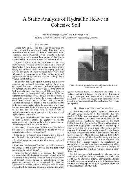
In non cohesive soils the expansion <strong>of</strong> the pore<br />
microstructure precedes hydraulic heave <strong>in</strong> a state <strong>of</strong><br />
liquefaction if there is no gra<strong>in</strong>-to-gra<strong>in</strong> contact pressure<br />
dur<strong>in</strong>g the different states. When develop<strong>in</strong>g hydraulic<br />
heave a movement <strong>of</strong> s<strong>in</strong>gle sand particles occurs at first<br />
followed by a temporary abrupt lift<strong>in</strong>g <strong>of</strong> the upper soil<br />
layers what can f<strong>in</strong>ally lead to a selective “boil<strong>in</strong>g” like a<br />
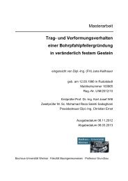
viscous fluid (see Fig. 1).<br />
To estimate the safety aga<strong>in</strong>st hydraulic heave <strong>in</strong> non<br />
cohesive soil, different calculation methods have been<br />
developed. The most conventional methods are presented<br />
by Terzaghi [8] and Davidenk<strong>of</strong>f [2]. A comparison <strong>of</strong><br />
both methods shows that the crucial difference between<br />
them is based on the regarded soil volume to def<strong>in</strong>e the<br />
representative seepage force. Terzaghi uses <strong>in</strong> his theory a<br />
quasi static equilibrium <strong>of</strong> act<strong>in</strong>g flow forces and resist<strong>in</strong>g<br />
dead load related to a def<strong>in</strong>ed soil cont<strong>in</strong>uum.<br />
Davidenk<strong>of</strong>f relates his theory to the maximum possible<br />
hydraulic gradient act<strong>in</strong>g along the sheet pile. In any case<br />
his approach gives the most conservative assumption due<br />
to the fact that the limit state is reached with a<br />
weightlessness <strong>of</strong> a s<strong>in</strong>gle gra<strong>in</strong> (σ eff < 0) when a local<br />
liquefaction <strong>of</strong> soil occurs.<br />
With regard to cohesive soils both methods are suitable<br />
to only a limited extent. To guarantee a feasible<br />
consideration <strong>of</strong> cohesion as the relevant parameter the<br />
follow<strong>in</strong>g questions have to be answered:<br />
- How does cohesion have <strong>in</strong>fluence on the failure<br />
process Does the simple model <strong>of</strong> the failure process <strong>in</strong><br />
non cohesive soil meet the conditions<br />
- Is the failure mechanism more a liquefaction <strong>of</strong> the soil<br />
or is the model <strong>of</strong> a wedge failure more adequate<br />
- At which stress state and at which location a crack will<br />
be <strong>in</strong>itiated<br />
- How does the change <strong>of</strong> the shear properties <strong>in</strong>fluence<br />
the change <strong>of</strong> the effective stresses and the pore water<br />
pressure <strong>in</strong> the state <strong>of</strong> failure<br />
Based on known theories to estimate the stability<br />
aga<strong>in</strong>st erosion a limitation <strong>of</strong> the range <strong>of</strong> application <strong>in</strong><br />
connection with hydraulic failure <strong>in</strong> form <strong>of</strong> liquefaction<br />
and through wedge failure <strong>in</strong> consideration <strong>of</strong> the<br />
parameter cohesion will be <strong>in</strong>troduced. To show an<br />
application <strong>of</strong> wedge failure a mechanic sensible basic<br />
approach will be presented <strong>in</strong> order to estimate the safety<br />
Figure 1. <strong>Hydraulic</strong> heave <strong>of</strong> a two layer soil system with a relative<br />
impervious top layer [4]<br />
aga<strong>in</strong>st hydraulic heave. To document the effect <strong>of</strong> a<br />
variable hydraulic <strong>in</strong>fluence on the stress distribution<br />
along a sheet pile wall results <strong>of</strong> calculations will be<br />
presented. To detect the failure type mentioned above<br />
experiments were carried out. The method and first results<br />
are reported.<br />
II. HYDRAULIC HEAVE IN COHESIVE SOIL<br />
To prove the safety aga<strong>in</strong>st hydraulic heave two<br />
different failure scenarios <strong>of</strong> the ultimate state are<br />
possible: A failure due to erosion <strong>of</strong> particles and a wedge<br />
failure mechanism. A failure due to erosion can be<br />
characterised as liquefaction depend<strong>in</strong>g on the local<br />
hydraulic gradient. Dur<strong>in</strong>g wedge failure a soil cont<strong>in</strong>uum<br />
breaks <strong>in</strong>to s<strong>in</strong>gle parts. The failure is <strong>in</strong>itiated by a<br />
discrete crack that will arise <strong>in</strong> a pre-failure state or can be<br />
produced by exceed<strong>in</strong>g the tensile strength. Liquefaction<br />
as well as wedge failure occurs if the effective stress <strong>in</strong> a<br />
soil becomes zero. Ma<strong>in</strong> difference between both failure<br />
mechanisms is the additional tensile strength with<strong>in</strong> a<br />
cohesive soil. Consequently <strong>in</strong> a non cohesive soil<br />
hydraulic heave occurs typically by liquefaction as<br />
consequence <strong>of</strong> a structure collapse due to dilatancy while<br />
wedge failure can only occur when a tensile strength <strong>of</strong><br />
the soil is activated or if a shear resistance arises <strong>in</strong> <strong>in</strong>ner<br />
shear zones.<br />
The different types <strong>of</strong> calculation have to be analysed <strong>in</strong><br />
order to estimate the effect <strong>of</strong> cohesion on limit state<br />
conditions. An analysis <strong>of</strong> different approaches to estimate<br />
the stability aga<strong>in</strong>st erosion leads to the follow<strong>in</strong>g criteria<br />
for erosion <strong>of</strong> s<strong>in</strong>gle gra<strong>in</strong>s or gra<strong>in</strong> aggregates expressed<br />
by the global factor <strong>of</strong> safety FoS.
critical gradient [-]<br />
1e+4<br />
1e+3<br />
1e+2<br />
1e+1<br />
1e+0<br />
Dp = 0,002 m<br />
0 2 4 6 8 10 12 14<br />
cohesion [kN/m²]<br />
Davidenk<strong>of</strong>f<br />
Rehfeld<br />
Müllner<br />
Zou<br />
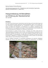
Figure 2. Comparison <strong>of</strong> erosion criteria accord<strong>in</strong>g to Davidenk<strong>of</strong>f [3],<br />
Rehfeld [5], Müllner [6] and Zou [10]; different percolated material<br />
and constant filter material<br />
Davidenk<strong>of</strong>f [3]<br />
Rehfeld [7]<br />
Müllner [6]<br />
Zou [10]<br />
6 c'<br />
FoS =<br />
tan ϕ'<br />
⋅ D ⋅<br />
c'<br />
FoS = 3<br />
2 ⋅ tan ϕ'<br />
⋅ D ⋅<br />
p<br />
p<br />
( γ ⋅ i − γ'<br />
)<br />
w<br />
6.<br />
2 c'<br />
FoS =<br />
D p<br />
⋅ i ⋅ γ<br />
( γ ⋅ i − γ'<br />
)<br />
w<br />
w<br />
( σ − γ ⋅ D ⋅ i)<br />
4 c' +<br />
x0<br />
w<br />
FoS =<br />
⎛ γ<br />
w<br />
2 ⋅ζ<br />
p +<br />
⎜<br />
⎝ T1<br />
p<br />
⋅ tan ϕ'<br />
⎞<br />
⋅ i − γ'<br />
⎟ ⋅ D<br />
⎠<br />
While the derivation <strong>of</strong> their erosion criteria the authors<br />
consider <strong>in</strong> [3], [5] and [6] the shear parameters ϕ’ and c’,<br />
the equivalent pore diameter <strong>of</strong> the filter soil D p and the<br />
gradient <strong>of</strong> the contact plane between the cohesive<br />
material and the filter soil relative to horizontal l<strong>in</strong>e,<br />
represented by the angle α. The context shown <strong>in</strong> formula<br />
(1) to (4) is significant for an upward flow out <strong>of</strong> the<br />
percolated soil <strong>in</strong>to the filter layer. Accord<strong>in</strong>g to the<br />
p<br />
approach <strong>of</strong> Zou a consideration <strong>of</strong> the pressure state is<br />
possible. In formula (4) he considered the effective lateral<br />
pressure σ x0 and the shear<strong>in</strong>g stress with<strong>in</strong> the erosion<br />
capillary ζ · p. A factor T 1 is def<strong>in</strong>ed to consider the fabric<br />
<strong>of</strong> the soil.<br />
Assum<strong>in</strong>g a safety factor <strong>of</strong> FoS = 1 the erosion criteria<br />
mentioned above are plotted <strong>in</strong> Fig. 2 as function <strong>of</strong> the<br />
critical gradient depend<strong>in</strong>g on cohesion for an upward<br />
directed flow. Constra<strong>in</strong>ts <strong>of</strong> the calculations were a<br />
constant friction angle (ϕ’ = 25°) represent<strong>in</strong>g the<br />
percolated soil and a constant equivalent pore diameter<br />
(Dp = 2 mm) represent<strong>in</strong>g the distance between the<br />
particles <strong>of</strong> the filter layer. The safety aga<strong>in</strong>st erosion and<br />
the result<strong>in</strong>g critical gradient are valid for the surface <strong>of</strong><br />
contact between the percolated soils as well as for the<br />
filter layer. At the same time the weight <strong>of</strong> the filter layer<br />
causes a stress <strong>in</strong> the contact pla<strong>in</strong>.<br />
The comparison <strong>of</strong> the presented criteria show a strong<br />
<strong>in</strong>crease <strong>of</strong> the critical gradient even with moderate ris<strong>in</strong>g<br />
cohesion. The functions describ<strong>in</strong>g the critieria <strong>of</strong><br />
Davidenk<strong>of</strong>f, Rehfeld and Müllner are look<strong>in</strong>g similar.<br />
Simplify<strong>in</strong>g the formulas leads to the def<strong>in</strong>ition <strong>of</strong> a<br />
straight l<strong>in</strong>e with different gradients. The root <strong>of</strong> the<br />
formulas, that is the <strong>in</strong>tersection <strong>of</strong> the graph and the axe<br />
<strong>of</strong> the critical gradient, is at a value <strong>of</strong> 1 for the criteria <strong>of</strong><br />
Davidenk<strong>of</strong>f and Rehfeld and zero for the formula<br />
accord<strong>in</strong>g to Müllner. Zou’s erosion criterion is<br />
recognisable due to its different shape (see Fig. 2). In a<br />
range <strong>of</strong> small cohesion (c’ ≤ 10 kN/m²) the critical<br />
hydraulic gradient is much higher compared to the other<br />
erosion criteria under the state <strong>of</strong> stress considered <strong>in</strong> his<br />
paper (see [10].)<br />
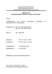
With<strong>in</strong> the scope <strong>of</strong> different experiments Leuss<strong>in</strong>k [5]<br />
(1) studied the <strong>in</strong>fluence <strong>of</strong> a vary<strong>in</strong>g f<strong>in</strong>e particle content <strong>of</strong><br />
soils with small cohesion (c’ < 5 kN/m²) with regard to<br />
strength and stiffness <strong>of</strong> soil mixtures. Besides the<br />
exam<strong>in</strong>ation <strong>of</strong> the shear strength and the pore pressure <strong>in</strong><br />
wide graded soils the experiments were focused on the<br />
safety aga<strong>in</strong>st erosion. Fig. 3 shows experimental<br />
(2) <strong>in</strong>vestigated failures accord<strong>in</strong>g to the permeability and the<br />
hydraulic gradient. In detail the po<strong>in</strong>ts <strong>in</strong> the figure mark a<br />
partially or total failure <strong>of</strong> the soil body by erosion <strong>of</strong> the<br />
f<strong>in</strong>e particle content. They are generalised as a function.<br />
Assum<strong>in</strong>g that cohesion and permeability are related<br />
<strong>in</strong>direct proportional it can be derivated that soils with less<br />
or quasi zero cohesion, respectively relative pervious<br />
(3) (3)<br />
(4)<br />
permaebility [m/s]<br />
1e-2<br />
1e-3<br />
1e-4<br />
1e-5<br />
wash<strong>in</strong>g<br />
c' ~ 0 to 10 kN/m²<br />
1e-6<br />
0 2 4 6 8 10 12<br />
hydraulic gradient [-]<br />
Figure 3. Correlation between permeability and critical gradient <strong>of</strong> soils<br />
with small cohesion [5]
with the simplified formula:<br />
p<br />
*<br />
= σ ' + σ<br />
(5)<br />
t<br />
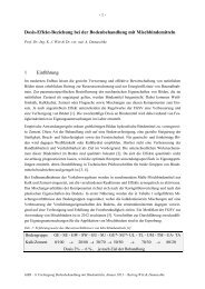
Figure 4. Different failure modes <strong>in</strong> cohesive soils [9]<br />
soils, will fail <strong>in</strong> range <strong>of</strong> a comparatively small hydraulic<br />
gradient, while the critical gradient <strong>in</strong>creases proportional<br />
with a ris<strong>in</strong>g cohesion and under the limit state <strong>of</strong> a<br />
constant friction angle and a equivalent pore diameter.<br />
All <strong>of</strong> the mentioned <strong>in</strong>vestigations <strong>in</strong>dicate that erosion<br />
failure due to a drop <strong>of</strong> hydraulic potential is only<br />
probable <strong>in</strong> soils with very small cohesion. Already <strong>in</strong><br />
cohesive soils a wedge failure mechanism with discrete<br />
elements or clods will be relevant. As demonstrated <strong>in</strong><br />
Fig. 4, soils with low cohesion will qualitatively fail as a<br />
certa<strong>in</strong> k<strong>in</strong>d <strong>of</strong> erosion (liquefaction) while soils with<br />
higher cohesion will fail due to a development <strong>of</strong> discrete<br />
shear planes as wedge failure mechanism or as a uplift <strong>of</strong><br />
discrete cracked layers. A semi quantitative analysis<br />
shows the possibility <strong>of</strong> a failure due to erosion up to a<br />
cohesion <strong>of</strong> approximately c’ ≤ 2,5 kN/m². <strong>Soil</strong>s with<br />
higher cohesion will fail <strong>in</strong> a more complex dimension<br />
after manifestation <strong>of</strong> a shear zone. Nevertheless for<br />
<strong>in</strong>itiat<strong>in</strong>g a wedge failure, discrete shear zones or <strong>in</strong>itial<br />
cracks are necessary to develop a pre-failure state. In case<br />
<strong>of</strong> a progressive development <strong>of</strong> dom<strong>in</strong>antly horizontal<br />
cracks the post failure conditions are equal to vertical<br />
uplift.<br />
Therefore <strong>in</strong> cohesive soils a wedge failure mechanism<br />
can be described by us<strong>in</strong>g the theory <strong>of</strong> effective stresses<br />
Accord<strong>in</strong>g to that a failure occurs if there is no effective<br />
stress σ’ and the excess pore water pressure p* is higher<br />
than the tensile strength σ t with<strong>in</strong> the soil cont<strong>in</strong>uum.<br />
Fig. 5 shows three different shaped failure bodies to<br />
f<strong>in</strong>d an upper bound or limit state due to a wedge failure<br />
mechanism on a sheet pile wall as a support <strong>of</strong> an<br />
excavation. Besides the consideration <strong>of</strong> rectangular,<br />
triangular and parabolic shaped bodies (I, II and IIIa) there<br />
are two different ways to build equilibrium <strong>of</strong> forces. At<br />
first the undra<strong>in</strong>ed cohesion c u can be considered as the<br />
representative resistance <strong>in</strong> a slip plane at limit state (see<br />
failure body I to IIIa). On the other hand the resistance at<br />
the stadium right before failure can be assumed by tak<strong>in</strong>g<br />
the achievable tensile strength <strong>of</strong> the soil <strong>in</strong>to<br />
consideration. The result<strong>in</strong>g equilibrium <strong>of</strong> forces is<br />
illustrated <strong>in</strong> Fig. 5 as failure body III b.<br />
The thickness <strong>of</strong> a failure body with the slightest safety<br />
aga<strong>in</strong>st hydraulic heave is described by the factor<br />
b = m · t. The shape and therefore m depends significant<br />
on the flow net. Assum<strong>in</strong>g a small embedd<strong>in</strong>g and a<br />
correspond<strong>in</strong>g flat shape <strong>of</strong> the flow net a relative broad<br />
area <strong>of</strong> <strong>in</strong>fluence will be developed. Reason for this is the<br />
<strong>in</strong>cl<strong>in</strong>ation <strong>of</strong> the flow forces. In such a case the thickness<br />
complies with m = 1/2 suggested by Terzaghi respectively<br />
b = 1/2 · t. If the embedd<strong>in</strong>g reaches deeper <strong>in</strong>to the<br />
ground the flow net will be orientated more vertical and<br />
the values <strong>of</strong> the parameter will be from approximately<br />
m = 1/3 to m = 1/4.<br />
The failure body IIIa shown <strong>in</strong> Fig. 6 describes the<br />
failure mechanism <strong>of</strong> a hydraulic heave <strong>in</strong> the most<br />
probable way. The parabolic surface <strong>of</strong> the failure body<br />
corresponds with the flow l<strong>in</strong>es <strong>of</strong> the flow net and<br />
therefore with the direction <strong>of</strong> flow <strong>in</strong>duced shear forces.<br />
In case <strong>of</strong> shear planes the residual shear strength<br />
represented by the undra<strong>in</strong>ed cohesion c u will be activated.<br />
Symbols: C u – vertical part <strong>of</strong> the force from undra<strong>in</strong>ed cohesion, G’ – dead load under uplift, S – stream<strong>in</strong>g force,<br />
Z – tensile force over width <strong>of</strong> the failure body, ∆h u – potential difference, m · t – width <strong>of</strong> the failure body<br />
Figure 5. Different types <strong>of</strong> wedge failure [9]
At the base <strong>of</strong> a wall the hydraulic gradient on a<br />
support<strong>in</strong>g sheet pile wall <strong>of</strong> an excavation reaches the<br />
highest values. The realisable potential difference at the<br />
base <strong>of</strong> the wall ∆h u is the excess head related to the<br />
deepest part <strong>of</strong> the sheet pile wall and can be estimated<br />
with formula 6:<br />
∆h<br />
u<br />
cu<br />
t ⋅ γ'<br />
+ 15 ,<br />
=<br />
m<br />
(6)<br />
γ<br />
w<br />
γ’ = submerged unit weight and γ w = unit weight <strong>of</strong><br />
water.<br />
III. ANALYSIS OF STRESS STATE<br />
In eng<strong>in</strong>eer<strong>in</strong>g practice there are two typical situations<br />
known for failure due to hydraulic heave, the downstream<br />
foot <strong>of</strong> a relative impervious dam or a weir above a<br />
pervious soil and an excavation with a impervious support<br />
(sheet pile). Referr<strong>in</strong>g to both seepage forces oppose the<br />
forces <strong>of</strong> gravity, neutraliz<strong>in</strong>g a part or the whole weight<br />
<strong>of</strong> the soil. Thus the effective stress and the shear strength<br />
decrease. To analyse the changes <strong>of</strong> stress and the<br />
deformation <strong>in</strong> a cohesive soil the <strong>in</strong>flow <strong>of</strong> an excavation<br />
was simulated by us<strong>in</strong>g the program PLAXIS and a briefly<br />
calculation <strong>of</strong> hydraulic pressures by PLAXFLOW. The<br />
geological circumstances are characterised by a cohesive<br />
soil located under a 10 m thick layer <strong>of</strong> non cohesive<br />
material.<br />
Referr<strong>in</strong>g to Fig. 6 the cross section <strong>of</strong> the system is<br />
characterised by gravel with its typical shear parameters,<br />
deformation behaviour and permeability. Under this<br />
relative permeable sediment there is a dense layer <strong>of</strong> silty<br />
and clayey sand. This soil shows typical low cohesive<br />
behaviour. The permeability <strong>of</strong> the gravel is more than<br />
100 times higher than those <strong>of</strong> the cohesive material. In<br />
general there is no activation <strong>of</strong> flow forces with<strong>in</strong> the<br />
gravel <strong>in</strong> comparison to the silt. For reasons <strong>of</strong> calculation<br />
there is no difference taken <strong>in</strong>to account between<br />
horizontal and vertical permeability with<strong>in</strong> both layers.<br />
In the first step the excavation and the <strong>in</strong>stallation <strong>of</strong> the<br />
support<strong>in</strong>g elements, thus the sheet pile wall and anchors,<br />
were <strong>in</strong>serted. Before rais<strong>in</strong>g the water level, it was<br />
def<strong>in</strong>ed at a depth similar to the bottom <strong>of</strong> the excavation.<br />
Fig. 6 illustrates an overview <strong>of</strong> the geological and<br />
hydrological conditions used with<strong>in</strong> the calculation.<br />
Aim <strong>of</strong> the numerical analysis was the determ<strong>in</strong>ation <strong>of</strong><br />
the change <strong>of</strong> the stress state and the result<strong>in</strong>g deformation<br />
around the sheet pile wall due to a rise <strong>of</strong> the water level,<br />
as depicted <strong>in</strong> Fig. 6 po<strong>in</strong>ts 1 to 4. The rise <strong>of</strong> water level<br />
was executed us<strong>in</strong>g the steady state algorithm <strong>of</strong> the<br />
program tool PLAXFLOW.<br />
To show the change <strong>of</strong> the stress state <strong>of</strong> the soil the<br />
effective stresses before and after the rise were<br />
documented <strong>in</strong> Fig. 6 details 3 and 4. But due to the lateral<br />
load from the support the effective stresses <strong>in</strong> f<strong>in</strong>al state<br />
don’t became zero. This fact leads to the result that failure<br />
due to hydraulic heave didn’t happen dur<strong>in</strong>g the<br />
calculation. The relative strong fixation <strong>of</strong> the sheet pile<br />
base <strong>in</strong> the soil abutment was partially loosened.<br />
Nevertheless <strong>in</strong> general an significant decrease <strong>of</strong> the<br />
1 – seepage forces, 2 – total shear sta<strong>in</strong>s, 3 – effective<br />
stress before rise <strong>of</strong> the water level, 4 – effective stress<br />
after rise <strong>of</strong> the water level<br />
Figure 6. Distributions <strong>of</strong> pore pressure, total and effective stresses<br />
effective stresses on the excavation sided wall can be<br />
determ<strong>in</strong>ed.<br />
Due to the fact that failure didn’t occur by hydraulic<br />
heave, the determ<strong>in</strong>ation <strong>of</strong> a failure body could not be<br />
executed. But by evaluat<strong>in</strong>g the total shear stra<strong>in</strong> plot (see<br />
Fig. 6 po<strong>in</strong>t 2) a spacious expansion <strong>of</strong> the excavation<br />
sided soil were ascerta<strong>in</strong>ed. The maximum value <strong>of</strong> shear<br />
stra<strong>in</strong> deformations were reached <strong>in</strong> direct contact to the<br />
sheet pile. This result <strong>in</strong>dicates that the ratio <strong>of</strong> seepage<br />
forces and dead load under uplift is comparatively small <strong>in</strong><br />
this area. Regard<strong>in</strong>g the whole soil expansion and the<br />
po<strong>in</strong>ts <strong>of</strong> maximum values a failure body with a width <strong>of</strong><br />
b ≈ ½ · t (accord<strong>in</strong>g to Terzaghi’s suggestion) can be<br />
derivated.<br />
To estimate the validity <strong>of</strong> formula 6 calculations <strong>of</strong> the<br />
safety factor and the possible critical hydraulic potential<br />
difference were executed. In case <strong>of</strong> a maximum water<br />
level beh<strong>in</strong>d the wall and a thickness <strong>of</strong> the failure body <strong>of</strong><br />
ca. 2 m, thus accord<strong>in</strong>g to Terzaghi m = 1/2, a safety <strong>of</strong><br />
FoS = 3,5 is <strong>in</strong>dicated. This result corresponds with the<br />
FEM calculations. Accord<strong>in</strong>g to formula 6 the calculated<br />
result represents exclusive the safety aga<strong>in</strong>st hydraulic<br />
heave. The result <strong>of</strong> the computational calculation<br />
conta<strong>in</strong>s <strong>in</strong> contrast to this effects <strong>of</strong> embedd<strong>in</strong>g the wall
and material properties <strong>of</strong> the wall, i. e. stiffness and<br />
strength.<br />
The most important result <strong>of</strong> this analysis is the<br />
documented <strong>in</strong>fluence <strong>of</strong> the flow direction on the<br />
probable shape <strong>of</strong> the failure body. In case <strong>of</strong> an almost<br />
cont<strong>in</strong>uous flow without any <strong>in</strong>fluences due to redirection<br />
on layer planes or constructions a flat soil will be uplifted.<br />
This result corresponds with observations made <strong>in</strong> similar<br />
cases. On the other hand the results <strong>of</strong> the sheet pile wall<br />
example show the strong <strong>in</strong>fluence when chang<strong>in</strong>g the<br />
flow net shape. In such cases the shape <strong>of</strong> the failure body<br />
will significantly be <strong>in</strong>fluenced by the permeability <strong>of</strong> the<br />
percolated soils and the thickness <strong>of</strong> such layers.<br />
The more concentrated a percolation occurs the th<strong>in</strong>ner<br />
the failure body shape will be.<br />
IV. VISUALISING OF THE FAILURE INITIATION<br />
Experiments were executed to visualise the failure<br />
process and to characterise the failure type <strong>in</strong> dependence<br />
on the cohesion. Furthermore the experiments should<br />
document the <strong>in</strong>itiation and the development <strong>of</strong> the failure<br />
process. The experimental study should demonstrate<br />
weather the failure <strong>in</strong> cohesive soil is more characteristic<br />
for liquefaction or for wedge uplift and how large is the<br />
value <strong>of</strong> the limit<strong>in</strong>g parameter cohesion c B between both<br />
failure types.<br />
The experimental equipment simulates a sheet pile wall<br />
as support<strong>in</strong>g element on an excavation. To m<strong>in</strong>imize the<br />
necessary potential difference with<strong>in</strong> the experimental box<br />
different material were <strong>in</strong>stalled on the upstream and the<br />
downstream side. The embedd<strong>in</strong>g <strong>of</strong> the wall on the<br />
upstream side consists <strong>of</strong> 10 mm clay and 90 mm coarse<br />
gra<strong>in</strong>ed filter material. On the downstream side the wall is<br />
fully embedded <strong>in</strong> the cohesive clay (see Fig. 7.) By<br />
<strong>in</strong>stall<strong>in</strong>g different permeable material on the different<br />
sides <strong>of</strong> the wall most <strong>of</strong> the seepage forces were activated<br />
on the downstream side with<strong>in</strong> the clay. Bažant carried out<br />
<strong>in</strong>vestigations (see [1]) to show that the deformations on<br />
the upstream side <strong>of</strong> a wall are comparatively smaller than<br />
those on the downstream side when reach<strong>in</strong>g hydraulic<br />
heave. The embedd<strong>in</strong>g <strong>in</strong> the clay can be <strong>in</strong>stalled as small<br />
as possible thus very small deformations are expected on<br />
the upstream side <strong>of</strong> the wall.<br />
After <strong>in</strong>stallation <strong>of</strong> the soil layer a saturation <strong>of</strong> the<br />
soils have to be executed. To <strong>in</strong>crease the velocity <strong>of</strong><br />
saturation the hydraulic stress level on both sides <strong>of</strong> the<br />
wall was cont<strong>in</strong>uously raised and held constant at a<br />
Figure 7. Experimental box with <strong>in</strong>stalled clay and filter material<br />
Figure 8. Result after failure (white l<strong>in</strong>e = slip plane)<br />
backpressure <strong>of</strong> approximately 50 kN/m².<br />
Due to a follow<strong>in</strong>g long term raise <strong>of</strong> the hydraulic head<br />
on the upstream side <strong>of</strong> the wall an expansion <strong>of</strong> the soil<br />
cont<strong>in</strong>uum on the downstream side were observed. This<br />
process was followed by the <strong>in</strong>itiation <strong>of</strong> a vertical crack<br />
at the end <strong>of</strong> the wall foot on the downstream side. In a<br />
constant stress state the first crack were enlarged and<br />
f<strong>in</strong>ally lead to a failure <strong>of</strong> the soil. Due to an <strong>in</strong>crease <strong>of</strong><br />
the act<strong>in</strong>g stress level the crack also <strong>in</strong>creases. F<strong>in</strong>ally the<br />
crack reaches the downstream surface. The consequence<br />
was a short term uplift <strong>of</strong> a discrete soil clod followed by a<br />
compensation <strong>of</strong> the different stress levels on both sides <strong>of</strong><br />
the wall. Dur<strong>in</strong>g the compensation the clod was destroyed<br />
and teared apart <strong>in</strong>to small aggregates and even particles<br />
<strong>of</strong> the soil. The result after the compensation is shown <strong>in</strong><br />
Fig. 8.<br />
The failure due to hydraulic heave occurs <strong>in</strong> the strong<br />
cohesive clay as a wedge mechanism. The <strong>in</strong>itial crack<br />
was realised when a total hydraulic stress difference <strong>of</strong><br />
25 kN/m² forces the soil. That is the excess hydraulic head<br />
related to the base <strong>of</strong> the wall was about ∆h u = 2 m. Aim<br />
<strong>of</strong> the experimental work is not to determ<strong>in</strong>e the stress at<br />
limit state, but to study the development <strong>of</strong> the failure <strong>in</strong><br />
cohesive soils. Nevertheless the first results correspond<br />
with formula 6.<br />
Fig. 8 shows the shape <strong>of</strong> the failure clod <strong>in</strong> a cross<br />
section. Regard<strong>in</strong>g the change <strong>of</strong> the failure body depth<br />
due to the <strong>in</strong>itial vertical crack the width <strong>of</strong> the failure<br />
body is about m ≈ 2. The result doesn’t correspond with<br />
the expected value <strong>of</strong> m = 1/2. Reason for the <strong>in</strong>vestigated<br />
shape could be the soil <strong>in</strong>stallation technique, which<br />
produces a horizontal layered soil cont<strong>in</strong>uum and<br />
anisotropic conditions concern<strong>in</strong>g density and<br />
permeability. When <strong>in</strong>stall<strong>in</strong>g the soil <strong>in</strong> a way that quasi<br />
isotropic properties are existent dur<strong>in</strong>g the experiment a<br />
change <strong>of</strong> the failure body shape is expected.<br />
As th<strong>in</strong>gs will develop another question has to be<br />
answered. How does the stress state at the wall base<br />
change the soil conditions dur<strong>in</strong>g <strong>in</strong>creas<strong>in</strong>g <strong>of</strong> the total<br />
potential difference Thus a comparison <strong>of</strong> the failure<br />
time with the change <strong>of</strong> pore water pressure on the wall<br />
foot will be estimated.<br />
Alternatively to the static approach (formula 6) the<br />
<strong>in</strong>itiation <strong>of</strong> cracks can be def<strong>in</strong>ed as limit state. This<br />
approach matches the conditions <strong>of</strong> hydraulic fractur<strong>in</strong>g to<br />
def<strong>in</strong>e a limit state. From a mechanical po<strong>in</strong>t <strong>of</strong> view the
<strong>in</strong>itiation <strong>of</strong> the crack will always be orthogonal to the<br />
direction <strong>of</strong> the smallest pr<strong>in</strong>ciple stress. In case <strong>of</strong> a<br />
start<strong>in</strong>g failure due to hydraulic heave this would be under<br />
consideration <strong>of</strong> soil decompression which leads f<strong>in</strong>ally to<br />
a lift<strong>in</strong>g <strong>of</strong> the bottom <strong>of</strong> the excavation. Accord<strong>in</strong>g to the<br />
documented results <strong>of</strong> the first experiments an <strong>in</strong>creas<strong>in</strong>g<br />
pore water pressure would force the expansion <strong>of</strong> the<br />
crack till the failure <strong>in</strong> form <strong>of</strong> hydraulic heave occurs.<br />
V. SUMMARY<br />
Aim <strong>of</strong> the present research is the exam<strong>in</strong>ation <strong>of</strong> the<br />
failure type, <strong>in</strong> detail liquefaction and wedge failure, due<br />
to hydraulic heave on a support<strong>in</strong>g wall <strong>of</strong> an excavation.<br />
The problem was analysed theoretically by comparison <strong>of</strong><br />
the critical hydraulic gradient <strong>in</strong> dependence <strong>of</strong> different<br />
erosion criteria, by computational calculations to validate<br />
the presented safety criteria <strong>of</strong> a wedge failure mechanism<br />
and by experiments to recognize the deformations pre and<br />
post failure.<br />
The <strong>in</strong>fluence <strong>of</strong> the cohesion on the failure process<br />
could be shown based on the comparison <strong>of</strong> different<br />
erosion criteria. To reach erosion <strong>in</strong> cohesive soils, i. e.<br />
structural collapse, a very high local hydraulic gradient<br />
would be necessary. This leads to the assumption that a<br />
wedge failure mechanism is valid even <strong>in</strong> low cohesive<br />
soils.<br />
The <strong>in</strong>troduced shapes <strong>of</strong> failure clods leads to the<br />
conclusion that the failure body on a sheet pile wall can be<br />
modelled as a parabolic clod <strong>in</strong> a first static<br />
approximation. The width <strong>of</strong> the mechanism depends<br />
significantly on the geological behaviour <strong>in</strong> the sphere <strong>of</strong><br />
<strong>in</strong>fluence. In this context layer<strong>in</strong>g and non isotropic<br />
permeability got the strongest <strong>in</strong>fluence on the shape. The<br />
presented formula to estimate the hydraulic potential<br />
difference at limit state can be used estimat<strong>in</strong>g the shape<br />
<strong>of</strong> the wedge. Generalis<strong>in</strong>g the thickness <strong>of</strong> the failure<br />
body will be half <strong>of</strong> the embedd<strong>in</strong>g, if isotropic conditions<br />
will be present. When us<strong>in</strong>g the formula to estimate the<br />
safety it is essential to realize that energy conversion<br />
while deformation and liquefaction <strong>of</strong> the soil as well as<br />
the horizontal fixation <strong>of</strong> the support<strong>in</strong>g are unconsidered.<br />
Summaris<strong>in</strong>g the first results <strong>of</strong> the study hydraulic<br />
heave <strong>in</strong> cohesive soils will arise as a wedge failure. Only<br />
soil with very small cohesion (ca. c’ ≤ 2,5 kN/m²) will fail<br />
<strong>in</strong> the manner described <strong>in</strong> the common formula by<br />
Terzaghi. The mechanism <strong>of</strong> failure <strong>in</strong> highly cohesive<br />
soils is dom<strong>in</strong>ated by the development <strong>of</strong> cracks. If they<br />
are already existent genetically failure will occur <strong>in</strong> a<br />
certa<strong>in</strong> type <strong>of</strong> uplift. The pr<strong>in</strong>ciple which leads to cracks<br />
due to pressure can be described by the phenomenon <strong>of</strong><br />
hydraulic fractur<strong>in</strong>g us<strong>in</strong>g an approach that considers the<br />
energy needed for deformation and the propagation <strong>of</strong><br />
cracks.<br />
ACKNOWLEDGEMENT<br />
The results presented <strong>in</strong> this contribution are part <strong>of</strong> an<br />
ongo<strong>in</strong>g research-work <strong>in</strong> the order <strong>of</strong> the German Federal<br />
Waterways Eng<strong>in</strong>eer<strong>in</strong>g and Research Institute – BAW.<br />
The fund<strong>in</strong>g assistance provided by the BAW <strong>in</strong> support<br />
<strong>of</strong> this project is gratefully acknowledged.<br />
REFERENCES<br />
[1] Z. Bažant, „Grundbruch unter e<strong>in</strong>er Spundwand“, „Bautechnik“<br />
(18), pp. 595 – 599, 1940<br />
[2] R. Davidenk<strong>of</strong>f, “Unterläufigkeit von Stauwerken,” Werner-<br />
Verlag GmbH, 1970.<br />
[3] R. Davidenk<strong>of</strong>f, „Anwendung von Filtern im Wasserbau“, Verlag<br />
Ernst & Sohn, 1976<br />
[4] W. Knaupe, „Aushub umschlossener Baugruben unter besonderer<br />
Berücksichtigung des hydraulischen Grundbruches im<br />
schichtweise gelagerten Baugrund“, Dissertation - Hochschule für<br />
Bauwesen Leipzig, 1972<br />
[5] H. Leuss<strong>in</strong>k, T. G. Visweswaraiya, H. Brendl<strong>in</strong>, „Beitrag zur<br />
Kenntnis der bodenphysikalischen Eigenschaften von<br />
Mischböden“, Veröff. Des Institutes für Bodenmechanik und<br />
Grundbau der Techn. Hochschule Fridericiana <strong>in</strong> Karlsruhe, 1964<br />
[6] B. Müllner, „Beitrag zur Untersuchung der Erosionssicherheit<br />
b<strong>in</strong>diger Mischböden bei vertikaler Durchströmung“, Mitt. des<br />
Fachgebietes Grundbau, Boden- und Felsmechanik<br />
Gesamthochschule Kassel – Universität, 1991<br />
[7] E. Rehfeld, „Die Erosionsbeständigkeit b<strong>in</strong>diger Lockergeste<strong>in</strong>e“,<br />
Wiss. Zeitschrift der TU Dresden, 5/67, pp. 1431 – 1437, 1967<br />
[8] K. Terzaghi, R. B. Peck, “<strong>Soil</strong> Mechanics <strong>in</strong> Eng<strong>in</strong>eer<strong>in</strong>g<br />
Practice,” John Wiley & Sons, 1. Corrected pr<strong>in</strong>t<strong>in</strong>g, 1968.<br />
[9] K. J. Witt, R.-B. Wudtke, „hydraulisch bed<strong>in</strong>gte Versagensformen<br />
<strong>in</strong> der Sohle von Baugruben“, BAW & Bauhaus-Universität<br />
Weimar, 2006<br />
[10] Y. Zou, „Der vom Spannungszustand und vom Bodengefüge<br />
abhängige Erosionsdurchbruch b<strong>in</strong>diger Böden“, Wasserwirtschaft<br />
(90), pp. 554 – 559, 2000