Feb. 05 - Power Equipment Company
Feb. 05 - Power Equipment Company
Feb. 05 - Power Equipment Company

Create successful ePaper yourself
Turn your PDF publications into a flip-book with our unique Google optimized e-Paper software.
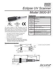
2.0 Flame Monitoring<br />
Flame monitoring must be provided by an ultraviolet<br />
scanner. Flame rod monitoring is not acceptable.<br />
Flame sensing equipment should be UL, FM and/or<br />
CSA approved.<br />
Refer to Eclipse Information Guide P-30 for specific<br />
details on the installation and use of flame monitoring<br />
equipment.<br />
WARNING<br />
Failure to use suitable flame sensing devices and<br />
automatic fuel shutoff valves can cause violent explosions<br />
and fires.<br />
3.0 Fuel and Pilot Air Supply<br />
The information in this guide is based on use of valve<br />
trains and/or components shown in Figure 1. It is the<br />
customer’s responsibility to supply approximately 2<br />
PSIG gas to the inlet when using these valve trains or<br />
similar components.<br />
4.0 Combustion Air Supply<br />
The customer must supply an air source for the pilot in<br />
the form of compressed air or other air sources as described<br />
in section 4.0. Pilot air consumption is 300<br />
SCFH.<br />
4.1 Air passing through the burner for combustion<br />
must contain 13% or more oxygen.<br />
4.2 Eclipse Incini-Cone burners operate at a pressure<br />
drop of between 0.5" and 3" w.c.—optimum operation<br />
is obtained at 2" to 2.5" w.c. drop.<br />
4.3 Profiling of the process stream is required. Refer<br />
to the Selection 420 for the necessary diameter<br />
of the profile plate orifice.<br />
4.4 The maximum upstream temperature to the<br />
Incinicone burner is 1100°F. Maximum downstream<br />
temperature is 1650°F.<br />
4.5 Process stream flow turndown is 2:1, based on a<br />
2" w.c. maximum pressure drop. Turndown can<br />
be extended to 2.45:1 with 3" w.c. pressure drop<br />
across the burner. Turndown should not be less<br />
than 0.5" w.c. pressure drop.<br />
5.0 Installation<br />
5.1 See Figure 2 for burner mounting. The bolt hole<br />
pattern for the mounting flange is given in Figure<br />
3.<br />
5.2 The customer must supply a gasket between the<br />
mounting flange and the chamber shell. Eclipse<br />
recommends 1/8" thick fiberglass rope or tape.<br />
5.3 The burner can be mounted or rotated in any position,<br />
and operate in any plane.<br />
5.4 Piping and electrical wiring must be done in accordance<br />
with all applicable local and/or insurance<br />
codes.<br />
5.5 The position of the gas gun is adjstaqble. Suggested<br />
starting position is 3" inside the basket,<br />
see Figure 3. It will only be necessray to adjust<br />
the burner position to overcome low flame signals<br />
or burner noise.<br />
6.0 Fuel and Pilot Air Piping<br />
6.1 Inspect all field piping during field assembly for<br />
foreign material and pipe scale. Clean piping will<br />
insure trouble free start-up and operation.<br />
6.2 Do not use teflon tape on threaded pipe connections<br />
to the burner assembly. Eclipse recommends<br />
the use of Locktite ® Teflon Pipe Sealant<br />
#9231 or equal. Sealant should be supplied according<br />
to manufacturer’s instruction.<br />
6.3 Use suitable brackets and/or hangers to support<br />
piping to the burner. Flexible connections on the<br />
main gas are mandatory and must allow the gas<br />
nozzle at least 6" movement into or out of the<br />
burner. Flexible connections are also recommended<br />
on the pilot air and gas lines.<br />
6.4 Install piping disconnects close to the burner for<br />
servicing. Inlet pipe sizes at the burner are adequate<br />
for short piping runs. If longer piping runs<br />
are required, piping losses must be considered<br />
and pipe sizes increased accordingly.<br />
6.5 On new installations, gas piping must be purged<br />
for air removal.<br />
6.6 Purge air should be piped to the UV scanner and<br />
peepsight inlets. The burner is supplied with piping<br />
tees specifically for purge air. See Figure 2.<br />
Provide sufficient purge air to overcome the<br />
chamber pressure and keep heat and moisture<br />
from working up the sight tubes.<br />
2