Metal Packing Vapor Distributors - Koch-Glitsch
Metal Packing Vapor Distributors - Koch-Glitsch
Metal Packing Vapor Distributors - Koch-Glitsch

You also want an ePaper? Increase the reach of your titles
YUMPU automatically turns print PDFs into web optimized ePapers that Google loves.
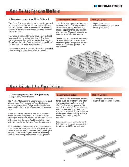
Model 716 Deck Type <strong>Vapor</strong> Distributor<br />
Diameters greater than 30 in. [760 mm]<br />
The Model 716 vapor distributor is a deck type used<br />
to correct poor vapor distribution below a packed<br />
bed. This device can be used between packed beds<br />
where a vapor feed is introduced or above reboiler<br />
return streams.<br />
The vapor is metered through vapor risers as liquid<br />
is collected from a packed bed above. The liquid<br />
leaves the vapor distributor through a downcomer.<br />
To perform the task of vapor distribution, the Model<br />
716 will consume some pressure drop.<br />
The turndown ratio is generally about 4 : 1, provided<br />
pressure drop is not excessive for the process.<br />
Construction Details<br />
The Model 716 vapor distributor is<br />
clamped to a support ring and typically<br />
requires bolting bars and segmental<br />
supports for its downcomer<br />
and seal pan. Midspan beams may be<br />
used for larger diameter towers.<br />
Standard construction will withstand<br />
50 lbs/ft 2 [0.024 bar] upward force.<br />
However, special designs are available<br />
which can withstand greater uplift<br />
requirements.<br />
Design Options<br />
• Liquid draw sump<br />
• Pipe downcomers, if applicable<br />
• Uplift specifications<br />
Model 746 Lateral Arm <strong>Vapor</strong> Distributor<br />
Diameters greater than 18 in. [450 mm]<br />
<strong>Vapor</strong>-only inlet streams<br />
The Model 746 lateral arm vapor distributor is used<br />
when a vapor feed requires uniform distribution<br />
across the tower area. Typical applications include<br />
vapor feed at the bottom of the tower or between<br />
beds.<br />
When used at the bottom of a tower it can save<br />
tower elevation compared to a deck type (model<br />
716) vapor distributor. When used between beds, it<br />
will ensure that the vapor feed is well distributed<br />
and well mixed with the vapor from the bed below.<br />
To achieve good distribution the required pressure<br />
drop across the vapor distributor is determined by<br />
the flow rate and size of the inlet. Turndown is generally<br />
4 : 1, but can be higher or lower depending<br />
upon the allowable pressure drop for the process.<br />
Construction Details<br />
The main header attaches to an inlet<br />
flange (supplied by others) and is further<br />
supported supplied by a wall<br />
clip. The laterals are supported by<br />
wall clips, as needed.Access diameter<br />
must be sufficient to accommodate<br />
the header assembly. For large diameter<br />
headers, where manway access is<br />
limiting, field welding may be<br />
required.<br />
Laterals are flanged as the standard,<br />
but may have threaded connections<br />
for pipes 4 in. [100 mm] and less.<br />
Design Options<br />
• All flanged construction<br />
• Bayonet-type for small columns<br />
23
Model 748 <strong>Vapor</strong> Diffuser<br />
Diameters greater than 48 in. [1200 mm]<br />
<strong>Vapor</strong>-only inlet streams<br />
The Model 748 vapor diffuser is used for vapor-only<br />
feeds where the flow energy is excessive. This<br />
device is not a vapor distributor. It reduces the<br />
vapor energy such that a more complex vapor<br />
distributor may not be necessary.<br />
The vapor diffuser uniformly meters the vapor<br />
stream out the upper area of the pipe and the<br />
shroud and then directs the flow downward to each<br />
side. The pressure drop across this device is<br />
relatively low compared to the Model 746 vapor<br />
distributor.<br />
Turndown is generally 4 : 1.<br />
Construction Details<br />
This device is attached to an internal<br />
tower inlet flange (supplied by<br />
others) and is further supported by<br />
a vessel wall clip as the standard<br />
construction.<br />
Optionally, the inside pipe can be<br />
designed to bayonet into the vapor<br />
inlet nozzle, in lieu of an internal<br />
flange.<br />
One-piece construction is standard<br />
provided column access diameter is<br />
sufficient. Otherwise, multi-piece<br />
construction is provided. In some<br />
cases, field welding of multi-piece<br />
construction may be required.<br />
Design Options<br />
• Bayonet inlet construction<br />
Model 768 EVENFLOW Vane Type <strong>Vapor</strong> Distributor<br />
Diameters greater than 72 in. [1800 mm]<br />
Preferred for vapor-only feed<br />
The Model 768 EVENFLOW vane type vapor distributor<br />
is used for high energy vapor inlet streams<br />
entering through a radial inlet. Although the device<br />
has been utilized in applications with high velocity<br />
mixed phase feeds, the performance of the device is<br />
best when limited to vapor-only feeds.<br />
Baffles used in conjunction with a tapered configuration<br />
provide vapor distribution with minimal pressure<br />
drop. The curved baffle plates partition the<br />
inlet vapor stream into multiple small segments,<br />
reducing the velocity and directing the segmented<br />
streams horizontally across the column area.<br />
Performance of the EVENFLOW vapor distributor<br />
has been validated using CFD analysis as well as<br />
numerous successful commercial installations.<br />
Construction Details<br />
Multi-piece construction is<br />
supplied for installation through<br />
a vessel manway. Flanged and<br />
bolted construction is supplied<br />
as the standard. Field welded construction<br />
is an available option.<br />
The inlet attachment requires welding<br />
to the vessel wall. Additional<br />
support clips welded to the vessel<br />
may be required. As an option,<br />
attachment can be made to an<br />
existing internal nozzle flange.<br />
Design Options<br />
• Field welded construction<br />
• Attachment to existing flange<br />
• CFD analysis<br />
24