Light Oil Burners RL 70/2 - 100/2 - 130/2 Low - High ... - AIRCO line
Light Oil Burners RL 70/2 - 100/2 - 130/2 Low - High ... - AIRCO line
Light Oil Burners RL 70/2 - 100/2 - 130/2 Low - High ... - AIRCO line

You also want an ePaper? Increase the reach of your titles
YUMPU automatically turns print PDFs into web optimized ePapers that Google loves.
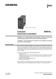
Installation, use and maintenance instructions<br />
<strong>Light</strong> <strong>Oil</strong> <strong>Burners</strong><br />
<strong>RL</strong> <strong>70</strong>/2 - <strong>100</strong>/2 - <strong>130</strong>/2<br />
<strong>Low</strong> - <strong>High</strong> Operation<br />
C6505052
CONTENTS<br />
WARNING<br />
TECHNICAL DATA. . . . . . . . . . . . . . . . . . . . . . . . . . . . . page 3<br />
Burner models . . . . . . . . . . . . . . . . . . . . . . . . . . . . . . . . . . . . . 3<br />
Accessories . . . . . . . . . . . . . . . . . . . . . . . . . . . . . . . . . . . . . . . 3<br />
Burner description . . . . . . . . . . . . . . . . . . . . . . . . . . . . . . . . . . 4<br />
Packaging - Weight. . . . . . . . . . . . . . . . . . . . . . . . . . . . . . . . . . 4<br />
Max. dimensions. . . . . . . . . . . . . . . . . . . . . . . . . . . . . . . . . . . . 4<br />
Standard equipment . . . . . . . . . . . . . . . . . . . . . . . . . . . . . . . . . 4<br />
Firing rate. . . . . . . . . . . . . . . . . . . . . . . . . . . . . . . . . . . . . . . . . 5<br />
INSTALLATION . . . . . . . . . . . . . . . . . . . . . . . . . . . . . . . . . . . . 6<br />
Boiler plate . . . . . . . . . . . . . . . . . . . . . . . . . . . . . . . . . . . . . . . . 6<br />
Blast tube length . . . . . . . . . . . . . . . . . . . . . . . . . . . . . . . . . . . 6<br />
Securing the burner to the boiler . . . . . . . . . . . . . . . . . . . . . . . 6<br />
Choice of nozzles for low and high fire . . . . . . . . . . . . . . . . . . . 6<br />
Nozzle assembly . . . . . . . . . . . . . . . . . . . . . . . . . . . . . . . . . . . 7<br />
Combustion head setting . . . . . . . . . . . . . . . . . . . . . . . . . . . . . 7<br />
Fuel supply. . . . . . . . . . . . . . . . . . . . . . . . . . . . . . . . . . . . . . . . 8<br />
Hydraulic connections . . . . . . . . . . . . . . . . . . . . . . . . . . . . . . . 8<br />
Pump . . . . . . . . . . . . . . . . . . . . . . . . . . . . . . . . . . . . . . . . . . . . 9<br />
Burner calibration . . . . . . . . . . . . . . . . . . . . . . . . . . . . . . . . . . 10<br />
Final check . . . . . . . . . . . . . . . . . . . . . . . . . . . . . . . . . . . . . . . 11<br />
Maintenance. . . . . . . . . . . . . . . . . . . . . . . . . . . . . . . . . . . . . . 11<br />
Burner operation. . . . . . . . . . . . . . . . . . . . . . . . . . . . . . . . . . . 12<br />
Factory wiring diagram - burner mounted LAL control. . . . . . . 13<br />
Field wiring diagram- burner mounted LAL control . . . . . . . . . 14<br />
Factory wiring diagram - remote panel . . . . . . . . . . . . . . . . . . 15<br />
Appendix - Burner firing rates according to air density. . . . . . . . . .16<br />
Siemens LAL control sequence of operations . . . . . . . . . . . . . 17<br />
Siemens LAL control troubleshooting guide . . . . . . . . . . . . . . 18<br />
Start up report . . . . . . . . . . . . . . . . . . . . . . . . . . . . . . . . . . . . 19<br />
Do not store flammable or hazardous materials in the vicinity<br />
of fuel burning appliances.<br />
Improper installation, adjustment, alteration, service or maintenance<br />
can cause property damage, personal injury or<br />
death. Refer to this manual for instructional or additional information.<br />
Consult a certified installer, service representative<br />
or the gas supplier for further assistance.<br />
Burner shall be installed in accordance with manufacturers<br />
requirements as out<strong>line</strong>d in this manual, local codes and authorities<br />
having juristiction.<br />
N.B.<br />
Figures mentioned in the text are identified as follows:<br />
1)(A) = part 1 of figure A, same page as text;<br />
1)(A)p.4 = part 1 of figure A, page number 4.<br />
2
TECHNICAL DATA<br />
MODEL <strong>RL</strong> <strong>70</strong> <strong>RL</strong> <strong>100</strong> <strong>RL</strong> <strong>130</strong><br />
Output (1)<br />
Delivery (1)<br />
<strong>High</strong> fire MBtu/hr (3)<br />
GPH<br />
1792 - 3136<br />
12.8 - 22.4<br />
2688 - 4480<br />
19.2 - 32<br />
<strong>Low</strong> fire MBtu/hr (3) 966 - 1792<br />
1344 - 2688<br />
GPH<br />
6.9 - 12.8<br />
9.6 - 19.2<br />
Fuel<br />
# 2 Fuel oil<br />
Operation<br />
<strong>Low</strong> - high<br />
Nozzles number 2<br />
Standard applications<br />
Hot water, steam, thermal oil<br />
Ambient temperature °F 32 - 104 (0 - 40 °C)<br />
Combustion air temperature °F max 140 (60 °C)<br />
Main power supply (+/- 10 %) V/Ph/Hz 208-230 / 460 / 575 / 3/60<br />
Fan motor<br />
rpm<br />
3400<br />
3400<br />
W - HP<br />
1<strong>100</strong> - 1.5<br />
1800 - 2.5<br />
V<br />
208 - 230/460/575 208 - 230/460/575<br />
A<br />
4.8 / 2.8 / 2.3<br />
6.7 / 3.9 / 3.2<br />
Ignition trasformer<br />
Pump<br />
delivery (174 Psi)<br />
pressure range<br />
V1 - V2<br />
I1 - I2<br />
GPH<br />
PSI<br />
34.3<br />
145 - 290<br />
120 V - 2 x 5 kV<br />
3.7 A - 35 mA<br />
52.5<br />
145 - 290<br />
3584 - 5824<br />
25.6 - 41.6<br />
1834 - 3584<br />
13.1 - 25.6<br />
3400<br />
2200 - 3<br />
208 - 230/460/575<br />
8.8 / 5.1 / 4.1<br />
Electrical power consumption W max 1400 2200 2600<br />
Electrical protection<br />
NEMA1<br />
Noise levels (2) dBA 68.0 <strong>70</strong>.0 <strong>70</strong>.0<br />
(1) Reference conditions: Ambient temperature 68° F (20° C) - Barometric pressure 394” WC - Altitude 329 ft.<br />
(2) Sound pressure measured in manufacturers combustion laboratory, with burner operating on test boiler and at maximum rated output.<br />
(3) Equivalent Btu values based on 1 USGPH = 140,000 Btu/hr.<br />
Burner models designations:<br />
Model Code Voltage Flame safeguard<br />
<strong>RL</strong> <strong>70</strong><br />
C9514200 (34750<strong>70</strong>)<br />
C9514201 (34750<strong>70</strong>)<br />
C9614200 (3475072)<br />
C9614201 (3475072)<br />
208-230/460/3/60<br />
575/3/60<br />
208-230/460/3/60<br />
575/3/60<br />
Burner mounted<br />
Burner mounted<br />
Remote panel<br />
Remote panel<br />
<strong>RL</strong> <strong>100</strong><br />
C9515200 (34752<strong>70</strong>)<br />
C9515201 (34752<strong>70</strong>)<br />
C9615200 (3475272)<br />
C9615201 (3475272)<br />
208-230/460/3/60<br />
575/3/60<br />
208-230/460/3/60<br />
575/3/60<br />
Burner mounted<br />
Burner mounted<br />
Remote panel<br />
Remote panel<br />
<strong>RL</strong> <strong>130</strong><br />
C9516200 (34754<strong>70</strong>)<br />
C9516201 (34754<strong>70</strong>)<br />
C9616200 (3475472)<br />
C9616201 (3475472)<br />
208-230/460/3/60<br />
575/3/60<br />
208-230/460/3/60<br />
575/3/60<br />
Burner mounted<br />
Burner mounted<br />
Remote panel<br />
Remote panel<br />
ACCESSORIES (optional):<br />
• Kit for lengthening the combustion head<br />
L = Standard length<br />
L1 = Length obtainable with the kit<br />
COD. 3010253 L = 927/32“ L1 = 155/32“ • <strong>RL</strong> <strong>70</strong><br />
COD. 3010254 L = 927/32“ L1 = 155/32“ • <strong>RL</strong> <strong>100</strong><br />
COD. 3010255 L = 927/32“ L1 = 155/32“ • <strong>RL</strong> <strong>130</strong><br />
Important:<br />
The installer is responsible for the supply and installation of any safety device(s) not indicated in this manual.<br />
3
(A)<br />
D2323<br />
D2324<br />
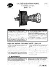
BURNER DESCRIPTION (A)<br />
1 Ignition electrodes<br />
2 Combustion head<br />
3 Screw for combustion head adjustment<br />
4 Screw for fixing fan to flange<br />
5 Slide bars for opening the burner and inspecting<br />
the combustion head<br />
6 Safety solenoid valve<br />
7 Pump<br />
8 Air inlet to fan<br />
9 Air damper<br />
10 Hydraulic cylinder for regulation of the air damper<br />
at low and high positions. When the burner is not<br />
operating the air damper is fully closed in order to<br />
reduce heat loss from the boiler.<br />
11 Fan pressure test point<br />
12 Boiler mounting flange<br />
13 Flame stability disk<br />
14 Electrical motor<br />
15 Extensions for slide bars 5)<br />
16 Ignition transformer<br />
17 Motor contactor and thermal cut-out with reset button<br />
18 <strong>Low</strong> and high fire valve assembly<br />
19 Terminal strip<br />
20 Two switches:<br />
- one "burner off - on"<br />
- one low - high operation"<br />
21 Knockouts for wiring carried out by the installer<br />
22 Flame safeguard with lock-out pilot light and lockout<br />
reset button<br />
23 Flame inspection window<br />
24 Pump pressure adjustment<br />
25 Photocell (cad cell)<br />
26 Air pressure switch<br />
Two types of burner failure may occur:<br />
• FLAME SAFEGUARD LOCK-OUT:<br />
if the Flame relay 22)(A) pushbutton lights up, it indicates<br />
that the burner is in lock-out.<br />
To reset, press the pushbutton.<br />
• MOTOR TRIP:<br />
release by pressing the pushbutton on thermal relay.<br />
inch A (1) B C lbs<br />
<strong>RL</strong><strong>70</strong><br />
<strong>RL</strong><strong>100</strong><br />
<strong>RL</strong><strong>130</strong><br />
(B)<br />
3725/32” - 459/32”<br />
3725/32” - 459/32”<br />
3725/32” - 459/32”<br />
235/8”<br />
235/8”<br />
235/8”<br />
2511/16”<br />
2511/16”<br />
2511/16”<br />
132<br />
139<br />
146<br />
D36<br />
PACKAGING-WEIGHT (B)<br />
Approximate measurements<br />
• The burner is shipped on a skid. Outer dimensions<br />
of packaging are indicated in (B)<br />
• The weight of the burner complete with packaging is<br />
indicated in table (B).<br />
MAX. DIMENSIONS (C)<br />
Approximate measurements<br />
The maximum dimensions of the burners are given in<br />
(C).<br />
Inspection of the combustion head requires the burner<br />
to be opened and the rear part withdrawn on the slide<br />
bars.<br />
The maximum dimension of the burner when open is<br />
given in measurement I.<br />
(C)<br />
<strong>RL</strong> A B C D E F (1) G H I (1)<br />
<strong>70</strong> 2227/32” 1121/32” 113/16” 2127/32” 2625/32” 927/32” - 155/32” 71/16” 1615/16” 377/16” - 423/4”<br />
<strong>100</strong> 2319/32” 129/32” 115/16” 2127/32” 2625/32” 927/32” - 155/32” 71/16” 1615/16” 377/16” - 423/4”<br />
<strong>130</strong> 245/8” 135/16” 115/16” 2127/32” 2625/32” 927/32” - 155/32” 77/16” 1615/16” 377/16” - 423/4”<br />
(1) Blast tube: short - long (obtainable with the kit)<br />
D686<br />
STANDARD EQUIPMENT<br />
2 - Flexible hoses<br />
1 - Head gasket<br />
4 - Screws to secure the burner flange to the boiler:<br />
1/2 W x 13/8”<br />
1 - Instruction booklet<br />
1 - Spare parts list<br />
1 - Adaptor G1/8” - 13/8” NPT<br />
4
FIRING RATE (A)<br />
The <strong>RL</strong> <strong>70</strong> - <strong>100</strong> - <strong>130</strong> Model burners can work in two<br />
ways: <strong>Low</strong> and <strong>High</strong> fire.<br />
comb. chamber “ WC comb. chamber “ WC comb. chamber “ WC<br />
LOW FIRE DELIVERY must be selected within area A<br />
of the adjacent diagrams.<br />
HIGH FIRE DELIVERY must be selected within area B<br />
(and C for model <strong>RL</strong> <strong>130</strong>). This area provides the maximum<br />
delivery of the burner in relation to the pressure<br />
in the combustion chamber.<br />
The firing rate may be found by plotting a vertical <strong>line</strong><br />
from the desired delivery and a horizontal <strong>line</strong> from the<br />
pressure in the combustion chamber. The intersection<br />
of these two <strong>line</strong>s is the firing rate which must lie within<br />
area B. In order to also utilize area C (<strong>RL</strong> <strong>130</strong>) it is necessary<br />
to perform the calibration of the combustion<br />
head as explained on page 6.<br />
Important:<br />
the FIRING RATE area values have been obtained<br />
considering an ambient temperature of 68° F (20 °C),<br />
and an atmospheric pressure of 394” WC (approx. 329<br />
ft above sea level) and with the combustion head adjusted<br />
as shown on page 7.<br />
Note:<br />
The FIRING RATE areas given in figure (A) have been<br />
reduced by 10% with respect to the maximum range that<br />
can be reached.<br />
Consult Appendix on page 16 for operation at different<br />
surrounding temperatures and/or altitudes.<br />
MINIMUM FURNACE DIMENSIONS (B)<br />
The firing rates were set in relation to certified test boilers.<br />
Figure (B) indicates the diameter and length of the test<br />
combustion chamber.<br />
Example<br />
Output 2579 MBTU/hr:<br />
diameter 24 inch - length 6.6 ft.<br />
(A)<br />
D2325<br />
Diameter (inches)<br />
Furnace dimensions<br />
Length (ft)<br />
(B)<br />
D2919<br />
5
INSTALLATION<br />
inch A B C<br />
<strong>RL</strong> <strong>70</strong> 79/32“ 1027/32“ - 1213/16“ 1/2 W<br />
<strong>RL</strong> <strong>100</strong> 79/32“ 1027/32“ - 1213/16“ 1/2 W<br />
<strong>RL</strong> <strong>130</strong> 79/32“ 1027/32“ - 1213/16“ 1/2 W<br />
(A)<br />
D455<br />
BOILER PLATE (A)<br />
Drill the combustion chamber mounting plate as<br />
shown in (A). The position of the threaded holes can<br />
be marked using the burner gasket supplied with the<br />
burner.<br />
BLAST TUBE LENGTH (B)<br />
The length of the blast tube must be selected according<br />
to the indications provided by the manufacturer of<br />
the boiler, and it must be greater than the thickness of<br />
the boiler door complete with its insulation. The range<br />
of lengths available, L (inch), is as follows:<br />
Blast tube 9): <strong>RL</strong> <strong>70</strong> <strong>RL</strong> <strong>100</strong> <strong>RL</strong> <strong>130</strong><br />
• short 927/32 927/32 927/32<br />
• long (with the kit) 155/32 155/32 155/32<br />
(B)<br />
D2326<br />
For boilers with front flue passes 12) or flame inversion<br />
chambers, protective insulation material 10) must be<br />
inserted between the boiler's refractory 11) and the<br />
blast tube 9).<br />
This protective insulation must not compromise the extraction<br />
of the blast tube.<br />
For boilers having a water-cooled front, the insulation<br />
10)-11)(B) is not required unless it is required by the<br />
boiler manufacturer.<br />
SECURING THE BURNER TO THE BOILER (B)<br />
Disassemble the blast tube 9) from the burner 6) by<br />
proceeding as follows:<br />
- Loosen the four screws 3) and remove the cover 1).<br />
- Remove the screws 2) from the two slide bars 5).<br />
- Remove the two screws 4) fixing the burner 6) to the<br />
flange 5).<br />
- Withdraw the blast tube 9) complete with flange 7)<br />
and slide bars 5).<br />
COMBUSTION HEAD CALIBRATION<br />
At this point check, for model <strong>RL</strong> <strong>130</strong>, whether the<br />
maximum delivery of the burner in high fire operation<br />
is contained in area B or in area C of the firing rate.<br />
See page 5.<br />
If it is in area B then no operation is required.<br />
If, on the other hand, it is in area C:<br />
- Unscrew the screws 1)(C) and disassemble the<br />
blast tube 5).<br />
- Unscrew the screws 3) and remove the shutter 4).<br />
- Tighten the screws 3) on the rod 2).<br />
- Now refit the blast tube 5) and the screws 1).<br />
Once this operation has been carried out (if required),<br />
secure flange 7)(B) to the boiler plate inserting the<br />
supplied gasket 8). Use the 4 screws provided after<br />
having protected the thread with an antiseize product<br />
(high-temperature grease, compounds, graphite). The<br />
burner-boiler seal must be airtight.<br />
(C)<br />
(D)<br />
Nozzle<br />
size<br />
5.0<br />
5.5<br />
6.0<br />
6.5<br />
7.0<br />
7.5<br />
8.0<br />
8.3<br />
8.5<br />
9.0<br />
9.5<br />
10.0<br />
10.5<br />
11.0<br />
12.0<br />
12.3<br />
13.0<br />
13.8<br />
14.0<br />
15.0<br />
15.3<br />
16.0<br />
17.0<br />
17.5<br />
18.0<br />
19.0<br />
19.5<br />
20.0<br />
21.5<br />
22.0<br />
D690<br />
GPH<br />
145 PSI 174 PSI 203 PSI<br />
6.15 6.79 7.40<br />
6.76 7.46 8.13<br />
7.40 8.17 8.87<br />
8.00 8.84 9.60<br />
8.61 9.51 10.34<br />
9.22 10.18 11.08<br />
9.86 10.85 11.81<br />
10.21 11.27 12.26<br />
10.47 11.56 12.55<br />
11.08 12.23 13.29<br />
11.69 12.90 14.06<br />
12.30 13.58 14.76<br />
12.94 14.28 15.50<br />
13.54 14.95 16.23<br />
14.76 16.30 17.71<br />
15.15 16.71 18.16<br />
16.01 17.64 19.18<br />
17.00 18.73 20.27<br />
17.23 19.02 20.65<br />
18.48 20.37 22.16<br />
18.83 20.78 22.57<br />
19.69 21.74 23.63<br />
20.94 23.09 25.10<br />
21.55 23.76 25.84<br />
22.16 24.46 26.58<br />
23.38 25.81 28.05<br />
24.01 26.48 28.79<br />
24.62 27.15 29.52<br />
26.48 29.20 31.73<br />
27.09 29.86 32.47<br />
MBtu/hr<br />
174 PSI<br />
951<br />
1044<br />
1144<br />
1238<br />
1331<br />
1425<br />
1519<br />
1578<br />
1618<br />
1712<br />
1806<br />
1901<br />
1999<br />
2093<br />
2282<br />
2339<br />
24<strong>70</strong><br />
2622<br />
2663<br />
2852<br />
2909<br />
3044<br />
3233<br />
3326<br />
3424<br />
3613<br />
3<strong>70</strong>7<br />
3801<br />
4088<br />
4180<br />
CHOICE OF NOZZLES FOR LOW AND HIGH FIRE<br />
Both nozzles must be chosen from among those listed<br />
in Table (D).<br />
The first nozzle determines the delivery of the burner<br />
at low fire.<br />
The second nozzle works in combination with the low<br />
fire nozzle to determine the delivery of the burner at<br />
high fire.<br />
The total deliveries of low and high fire must be contained<br />
within the value range indicated on page 3.<br />
Use nozzles with a 60° spray angle at the recommended<br />
pressure of 174 PSI.<br />
6
D2281<br />
The two nozzles usually have equal deliveries, but the<br />
low fire nozzle may have the following specifications if<br />
required:<br />
• a delivery less than 50% of the total delivery whenever<br />
the back-pressure peak must be reduced at the<br />
moment of firing: the burner allows good combustion<br />
values also with a ratio 40 - <strong>100</strong> % between low and<br />
high fire;<br />
• a delivery higher than 50% of the total delivery<br />
whenever the combustion during low fire must be<br />
improved.<br />
Example with the <strong>RL</strong> <strong>70</strong> Model:<br />
Boiler output = 2<strong>130</strong> MBTU/hr - efficiency 80 %<br />
Output required by the burner =<br />
2<strong>130</strong> : 0.8 = 2662 MBTU/hr;<br />
2662 : 2 = 1331 MBTU/hr per nozzle;<br />
therefore, two equal, 60°, 174 PSI nozzles are required:<br />
1° = 7.0 GPH - 2° = 7.0 GPH,<br />
or the following two different nozzles:<br />
1° = 6.0 GPH - 2° = 8.0 GPH,<br />
or:<br />
1° = 8.0 GPH - 2° = 6.0 GPH.<br />
(A)<br />
D691<br />
(B)<br />
D2360<br />
(C)<br />
NOZZLE ASSEMBLY<br />
At this stage of installation the burner is still disassembled<br />
from the blast tube; it is now possible to install the<br />
two nozzles, after having removed the plastic plugs<br />
2)(A), fitting the wrench through the central hole in the<br />
flame stability disk.<br />
Do not use any sealing products such as gaskets,<br />
sealing compound, or tape. Be careful to avoid damaging<br />
the nozzle sealing seat. The nozzles must be<br />
screwed into place tightly but carefully.<br />
The nozzle for low fire operation is the one lying beneath<br />
the firing electrodes Fig. (B).<br />
(D)<br />
SETTING THE COMBUSTION HEAD<br />
D694<br />
Make sure that the electrodes are positioned as shown<br />
in Figure (B).<br />
Finally remount the burner 3)(C) to the slide bars 2)<br />
and slide it up to the flange 5), keeping it slightly raised<br />
to prevent the flame stability disk from pressing<br />
against the blast tube.<br />
Tighten the screws 1) on the slide bars 2) and screws<br />
4) fixing the burner to the flange.<br />
If it proves necessary to change a nozzle with the<br />
burner already fitted to the boiler, proceed as out<strong>line</strong>d<br />
below:<br />
- Retract the burner on its slide bars as shown in<br />
fig. (B)p.6.<br />
- Remove the nuts 1)(D) and the disk 2).<br />
- Use wrench 3)(D) to change the nozzles.<br />
(E)<br />
N° Notches<br />
D462<br />
COMBUSTION HEAD SETTING<br />
The setting of the combustion head depends exclusively<br />
on the delivery of the burner at high fire - in other<br />
words, the combined delivery of the two nozzles selected<br />
on page 6. Turn screw 4)(E) until the notch<br />
shown in diagram (F) is level with the front surface of<br />
flange 5)(E).<br />
Example:<br />
The <strong>RL</strong> <strong>70</strong> Model with two 6.00 GPH nozzles and 174<br />
PSI pump pressure.<br />
Find the delivery of the two 6.00 GPH nozzles in table<br />
(D), page 6:<br />
8.17 + 8.17 = 16.34 GPH.<br />
Diagram (F) indicates that for a delivery of 16.34 GPH<br />
the <strong>RL</strong> <strong>70</strong> Model requires the combustion head to be<br />
set to approx. three notches, as shown in Figure (E).<br />
(F)<br />
D2327<br />
Fuel oil delivery at high fire<br />
USGPH<br />
7
HYDRAULIC SYSTEM<br />
L (ft)<br />
+ H<br />
<strong>RL</strong> <strong>70</strong> <strong>RL</strong> <strong>100</strong> - <strong>130</strong><br />
- H<br />
Ø (inch)<br />
Ø (inch)<br />
(ft)<br />
3/8” 1/2” 5/8” 3/8” 1/2” 5/8”<br />
+ 13 168 368 493 234 454 493<br />
+ 10 148 326 493 204 401 493<br />
+ 6.6 128 283 493 174 399 493<br />
+ 3.3 105 240 474 145 296 493<br />
+ 1.6 95 217 434 132 2<strong>70</strong> 493<br />
0 85 197 395 118 243 451<br />
- 1.6 76 178 355 105 217 405<br />
- 3.3 66 155 316 92 191 359<br />
- 6.6 43 112 234 63 138 266<br />
- 10 23 69 151 33 86 174<br />
- 13 – 26 69 – 33 82<br />
(A)<br />
HYDRAULIC CONNECTIONS<br />
6<br />
6<br />
315/16”<br />
7 5<br />
4<br />
- H + H V<br />
P<br />
5<br />
7<br />
A<br />
1<br />
B<br />
3<br />
D737<br />
2<br />
D2328<br />
FUEL SUPPLY<br />
Double-pipe circuit (A)<br />
The burner is equipped with a self-priming pump which<br />
is capable of feeding itself within the limits listed in the<br />
table at the left.<br />
The tank higer than the burner A<br />
The distance "P" must not exceed 32 ft in order to<br />
avoid subjecting the pump's seal to excessive strain;<br />
the distance "V" must not exceed 13 ft in order to permit<br />
pump self-priming even when the tank is almost<br />
completely empty.<br />
The tank lower than the burner B<br />
Pump suction values higher than 6.5 PSI must not be<br />
exceeded because at higher levels gas is released<br />
from the fuel, the pump starts making noise and its<br />
working life-span decreases.<br />
It is good practice to ensure that the return and suction<br />
<strong>line</strong>s enter the burner from the same height; in this way<br />
it will be less probable that the suction <strong>line</strong> fails to<br />
prime or stops priming.<br />
The loop circuit<br />
A loop circuit consists of a loop of piping exiting and returning<br />
to the tank with an auxiliary pump that circulates<br />
the fuel under pressure. A branch connection<br />
from the loop goes to feed the burner. This circuit is extremely<br />
useful whenever the burner pump does not<br />
succeed in self-priming because the tank distance<br />
and/or height difference are higher than the values listed<br />
in the table.<br />
Key (A)<br />
H = Pump/Foot valve height difference<br />
L = Piping length<br />
Ø = Inside pipe diameter<br />
1 = Burner<br />
2 = Pump<br />
3 = Filter<br />
4 = Manual on/off valve<br />
5 = Suction <strong>line</strong><br />
6 = Foot valve<br />
7 = Return <strong>line</strong><br />
HYDRAULIC CONNECTIONS (B)<br />
The pumps are equipped with a by-pass that connects<br />
return <strong>line</strong> and suction <strong>line</strong>. The pumps are installed on<br />
the burner with the by-pass closed by screw 6)(A)p.12.<br />
It is therefore necessary to connect both hoses to the<br />
pump.<br />
The pump seal will be damaged immediately if it is<br />
run with the return <strong>line</strong> closed and the bi-pass<br />
screw inserted.<br />
Remove the plugs from the suction and return connections<br />
of the pump.<br />
Insert the hose connectors with the supplied seals into<br />
the connections and screw them down.<br />
Take care that the hoses are not stretched or twisted<br />
during installation.<br />
Install the hoses where they cannot be stepped on or<br />
come into contact with hot surfaces of the boiler.<br />
Now connect the other end of the hoses to the supplied<br />
nipples, using two wrenches, one to hold the nipple<br />
steady while using the other one to turn the rotary union<br />
on the hose.<br />
(B)<br />
8
<strong>RL</strong> <strong>70</strong> - <strong>100</strong> - <strong>130</strong>: SUNTEC AJ6<br />
D2329<br />
PUMP (A)<br />
1 - Suction 1/4” NPT<br />
2 - Return 1/4” NPT<br />
3 - Pressure gauge attachment G 1/8<br />
4 - Vacuum gauge attachment G 1/8<br />
5 - Pressure adjustment screw<br />
6 - Screw for by-pass<br />
A - Min. delivery rate at 174 PSI pressure<br />
B - Delivery pressure range<br />
C - Max. suction pressure<br />
D - Viscosity range<br />
E - <strong>Light</strong> oil max. temperature<br />
F - Max. suction and return pressure<br />
G - Pressure calibration in the factory<br />
H - Filter mesh width<br />
PUMP PRIMING<br />
- Before starting the burner, make sure that the<br />
tank return <strong>line</strong> is not clogged. Obstructions in<br />
the <strong>line</strong> could cause the seal located on the<br />
pump shaft to break. (The pump leaves the factory<br />
with the by-pass closed).<br />
- In order for self-priming to take place, one of the<br />
screws 3)(A) of the pump must be loosened in order<br />
to bleed off the air contained in the suction <strong>line</strong>.<br />
- Start the burner by closing the control circuit and<br />
with switch 1)(C)p.10 in the "ON" position. The<br />
pump must rotate in the direction of the arrow<br />
marked on the cover.<br />
- The pump can be considered to be primed when the<br />
light oil starts coming out of the screw 3). Stop the<br />
burner: switch 1)(C)p.12 set to "OFF" and tighten<br />
the screw 3).<br />
The time required for this operation depends upon the<br />
diameter and length of the suction tubing. If the pump<br />
fails to prime at the first starting of the burner and the<br />
burner locks out, wait approx. 15 seconds, reset the<br />
burner, and then repeat the starting operation as often<br />
as required. After 5 or 6 starting operations allow 2 or<br />
3 minutes for the transformer to cool.<br />
Do not illuminate the photocell or the burner will lock<br />
out; the burner should lock out anyway about 10 seconds<br />
after it starts.<br />
Important:<br />
The priming operation is possible because the pump is<br />
already full of fuel when it leaves the factory. If the<br />
pump has been drained, fill it with fuel through the<br />
opening on the vacuum gauge prior to starting; otherwise,<br />
the pump will seize. Whenever the length of the<br />
suction piping exceeds 66-99 ft, the supply <strong>line</strong> must<br />
be filled using a separate pump.<br />
(A)<br />
A<br />
B<br />
C<br />
D<br />
E<br />
F<br />
G<br />
H<br />
PUMP<br />
GPH<br />
PSI<br />
PSI<br />
cSt<br />
°F - °C<br />
PSI<br />
PSI<br />
inch<br />
AJ6<br />
53<br />
145 - 290<br />
6.5<br />
2,8 - 75<br />
140 - 60<br />
29<br />
174<br />
0,006<br />
9
BURNER CALIBRATION<br />
FIRING<br />
Set switch 1)(C) to "ON".<br />
During the first firing, during the switch over from low<br />
to the high fire, there is a momentary lowering of the<br />
fuel pressure caused by the filling of the high fire nozzle<br />
tubing. This lowering of the fuel pressure can<br />
cause the burner to lock-out and can sometimes give<br />
rise to pulsations.<br />
Once the following adjustments have been made, the<br />
firing of the burner must generate a noise similar to the<br />
noise generated during operation.<br />
(A)<br />
D699<br />
(B)<br />
OPERATION<br />
The optimum calibration of the burner requires an<br />
analysis of the flue gases at the boiler outlet and adjustments<br />
at the following points:<br />
• <strong>Low</strong> and high fire nozzles<br />
See the information listed on page 6.<br />
• Combustion head<br />
The adjustment of the combustion head already carried<br />
out need not be altered unless the high fire delivery<br />
of the burner is changed.<br />
• Pump pressure<br />
174 PSI: this is the pressure calibrated in the factory<br />
which is usually sufficient for most purposes. Sometimes,<br />
this pressure must be adjusted to:<br />
145 PSI in order to reduce fuel delivery. This adjustment<br />
is possible only if the ambient temperature remains<br />
above 0°C. Never calibrate to pressures below<br />
145 PSI, at which pressures the cylinders may have<br />
difficulty in opening;<br />
203 PSI order to increase fuel delivery or to ensure<br />
firings even at temperatures of less than 0°C.<br />
In order to adjust pump pressure, use the relevant<br />
screw 5)(A)p.11.<br />
• <strong>Low</strong> fire air damper<br />
Keep the burner operating at low fire by setting the<br />
switch 2)(C) to the low position. Opening of the air<br />
damper 6)(B) must be adjusted in proportion to the<br />
selected nozzle: the index 1)(A) must be aligned with<br />
the notch 2)(A) specified in table (D). This adjustment<br />
is achieved by turning the hex element 2)(B):<br />
- in rh direction (- sign) the opening is reduced<br />
- in lh direction (+ sign) the opening increases.<br />
Example <strong>RL</strong> <strong>70</strong> - <strong>Low</strong> fire nozzle 6.00 GPH:<br />
2.3 (A) notch aligned with index 1)(A).<br />
When the adjustment is done lock the hex element<br />
2)(B) with the ring nut 1).<br />
• <strong>High</strong> fire air damper<br />
Set switch 2)(C) to the high position and adjust the<br />
air damper 6)(B) by turning the hex element 4)(B), after<br />
having loosened the ring nut 3)(B).<br />
Air pressure at attachment 1)(E) must be approximately<br />
the same as the pressure specified in table<br />
(E) plus the combustion chamber pressure measured<br />
at attachment 2). Refer to the example in the<br />
adjacent figure.<br />
NOTE:<br />
in order to facilitate adjustment of hex elements 2) and<br />
4)(B), use a 1/8” Allen key 5)(B).<br />
Burner<br />
1 2<br />
Stage<br />
Off<br />
1°<br />
On 2°<br />
(C)<br />
<strong>Low</strong> fire<br />
(D)<br />
<strong>High</strong> fire<br />
Nozzle<br />
size<br />
GPH<br />
5<br />
6<br />
7<br />
8<br />
9<br />
Nozzle<br />
size<br />
GPH<br />
13<br />
16<br />
19<br />
22<br />
<strong>RL</strong> <strong>70</strong> <strong>RL</strong> <strong>100</strong> <strong>RL</strong> <strong>130</strong><br />
N°<br />
2<br />
2.3<br />
2.6<br />
2.7<br />
2.8<br />
Nozzle<br />
size<br />
GPH<br />
7<br />
8<br />
9<br />
10<br />
11<br />
12<br />
13<br />
14<br />
N°<br />
2<br />
2.1<br />
2.2<br />
2.4<br />
2.6<br />
2.7<br />
2.8<br />
2.9<br />
Nozzle<br />
size<br />
GPH<br />
10<br />
11<br />
12<br />
13<br />
14<br />
15<br />
16<br />
17<br />
18<br />
19<br />
<strong>RL</strong> <strong>70</strong> <strong>RL</strong> <strong>100</strong> <strong>RL</strong> <strong>130</strong><br />
“WC<br />
3.3<br />
3.4<br />
3.5<br />
3.6<br />
Nozzle<br />
size<br />
GPH<br />
19<br />
22<br />
26<br />
29<br />
32<br />
“WC<br />
2.8<br />
3.0<br />
3.3<br />
3.7<br />
4.3<br />
D469<br />
“WC = Air pressure in 1) with zero pressure in 2)<br />
(1) Without shutter 4)(C)p.6<br />
Nozzle<br />
size<br />
GPH<br />
26<br />
29<br />
32<br />
35<br />
38<br />
42<br />
N°<br />
2<br />
2.1<br />
2.2<br />
2.3<br />
2.5<br />
2.6<br />
2.7<br />
2.8<br />
2.9<br />
3<br />
“WC<br />
2.7<br />
2.8<br />
3.0<br />
3.2<br />
3.5<br />
4.3<br />
3.3 (1)<br />
D2330<br />
(E)<br />
10
D<strong>70</strong>7<br />
FINAL CHECKS<br />
• Obscure the photocell and switch on the control devices:<br />
the burner should start and then lock-out about 5 s<br />
after opening of the low fire nozzle operation valve.<br />
• Illuminate the photocell and switch on the control circuit:<br />
the burner should go into lock-out .<br />
• Obscure the photocell while the burner is in high fire<br />
operation, the following must occur in sequence: flame<br />
extinguished within 1 s, pre-purging for about 20 s,<br />
sparking for about 5 s, burner goes into lock-out.<br />
• Switch off control device TL followed by control device<br />
TS while the burner is operating: the burner should stop.<br />
(A)<br />
(B)<br />
(D)<br />
(E)<br />
D2365<br />
X<br />
dimension<br />
D<strong>70</strong>9<br />
(C)<br />
D2361<br />
D2854<br />
MAINTENANCE<br />
Combustion<br />
An analysis of the flue gases is required at the boiler<br />
outlet. Significant differences with respect to the previous<br />
measurements indicate the points where more care<br />
should be exercised during maintenance.<br />
Pump<br />
The pump delivery pressure must be stable at 174 PSI.<br />
The suction must be less than 6.5 PSI.<br />
Unusual noise must not be evident during pump operation.<br />
If the pressure is found to be unstable or if the pump<br />
runs noisily, the flexible hose must be detached from the<br />
<strong>line</strong> filter and the fuel must be sucked from a tank<br />
located near the burner. This measure permits the<br />
cause of the anomaly to be traced to either the suction<br />
<strong>line</strong> or the pump.<br />
If the problem lies in the suction <strong>line</strong>, check to make<br />
sure that the filter is clean and that air is not entering<br />
the piping.<br />
Filters (A)<br />
Check the following filter boxes:<br />
• on <strong>line</strong> 1) at pump 2) • at nozzle 3), and clean or<br />
replace as required.<br />
If rust or other impurities are observed inside the pump,<br />
use a separate pump to suck out any water and other<br />
impurities that may have deposited on the bottom of the<br />
tank.<br />
Fan<br />
Check to make sure that no dust has accumulated<br />
inside the fan or on its blades, as this condition will<br />
cause a reduction in the air flow rate and produce<br />
incomplete combustion.<br />
Combustion head<br />
Check to make sure that all the parts of the combustion<br />
head are in good condition, positioned correctly, free of<br />
all impurities, and that no deformation has been caused<br />
by operation at high temperatures.<br />
Nozzles<br />
Do not clean the nozzle orifices.<br />
Replace the nozzles every 2-3 years or whenever necessary.<br />
Combustion must be checked after the nozzles<br />
have been changed.<br />
Photocell (cad cell) (B)<br />
Clean the glass cover from any dust that may have<br />
accumulated. Photocell 1) can be removed by pulling it<br />
outward forcefully.<br />
Flame inspection window (C)<br />
Clean the glass.<br />
Flexible hoses<br />
Check to make sure that the flexible hoses are still in<br />
good condition.<br />
Boiler<br />
Clean the boiler as indicated in its accompanying<br />
instructions in order to maintain all the original combustion<br />
characteristics intact, especially the flue gas temperature<br />
and combustion chamber pressure. Lastly,<br />
check the condition of the flue gas stack.<br />
TO OPEN THE BURNER (D)<br />
- Switch off the electrical power.<br />
- Loosen screws 1) and withdraw the cover 2).<br />
- Unscrew screws 3).<br />
- Fit the two extensions 4) supplied with the burner onto<br />
the slide bars 5) (model with long blast tube, obtainable<br />
rwith the kit).<br />
- Pull part A backward keeping it slightly raised to avoid<br />
damaging the disk 6) on blast tube 7).<br />
FUEL PUMP AND/OR COUPLINGS REPLACEMENT (E)<br />
As per fig. (E), dimension X should set as follows:<br />
<strong>RL</strong><strong>70</strong> - 11/2”<br />
<strong>RL</strong><strong>100</strong> - 17/16”<br />
<strong>RL</strong><strong>130</strong> - 17/16”<br />
11
BURNER OPERATION<br />
BURNER STARTING (A)<br />
Operating control closes.<br />
The motor starts and the ignition transformer is connected.<br />
The pump 3) sucks the fuel from the tank through the<br />
piping 1) and the filter 2) and pumps it under pressure<br />
to delivery. The piston 4) rises and the fuel returns to<br />
the tank through the piping 5) - 7). The screw 6) closes<br />
the by-pass heading towards suction and the solenoid<br />
valves 8) - 11) - 16), de-energized, close the passage<br />
to the nozzles.<br />
The hydraulic cylinder 15), piston A, opens the air damper:<br />
pre-purging begins with the low fire air delivery.<br />
At the opening of the solenoid valves 8) and 16) open<br />
and the fuel passes through the piping 9) and filter 10)<br />
and is then sprayed out through the nozzle, igniting<br />
when it comes into contact with the spark. This is the<br />
low fire flame.<br />
If the high fire control device is closed or has been replaced<br />
by with a jumper wire, the high fire solenoid<br />
valve 11) is opened and the fuel enters the valve 12)<br />
and raises the piston which opens two passages: one<br />
to piping 13), filter 14), and the high fire nozzle, and<br />
the other to the cylinder 15), piston B, that opens the<br />
fan air damper at high fire.<br />
FIRING FAILURE<br />
If the burner does not fire, it goes into lock-out within 5<br />
s of the opening of the low fire solenoid valve.<br />
The flame relay pilot light will light up.<br />
LOCKOUT DURING OPERATION<br />
If the flame goes out during operation, the burner shuts<br />
down automatically within 1 second and automatically<br />
attempts to start again by repeating the starting cycle.<br />
(A)<br />
D2331<br />
12
Factory Wiring Diagram<br />
<strong>RL</strong><strong>70</strong> - <strong>130</strong> three phase with burner mounted Siemens LAL control<br />
D2428<br />
Continuous fan operation<br />
Change the wire connection from terminal 7 to terminal 1, remove the jumper between terminals 12-13 and<br />
the wire from terminal 13 of control box.<br />
(A)<br />
LAYOUT (A)<br />
<strong>Burners</strong> <strong>RL</strong> <strong>70</strong> - <strong>100</strong> - <strong>130</strong><br />
The flame safeguard is on burner mounted<br />
• Models <strong>RL</strong> <strong>70</strong> - <strong>100</strong> - <strong>130</strong> leave the factory preset for 208-230<br />
V power supply.<br />
• If 460 V power supply is used, change the motor connection<br />
from delta to star and change the setting of the thermal overload.<br />
Key to Layout (A)<br />
CMV - Motor contactor<br />
DA - Control box<br />
FR<br />
I1<br />
I2<br />
MV<br />
MB<br />
P<br />
TA<br />
TB<br />
V1<br />
V2<br />
VS<br />
RT<br />
D2872<br />
- Photocell<br />
- Switch: burner off - on<br />
- Switch: low - high fire operation<br />
- Fan motor<br />
- Burner terminal strip<br />
- Air pressure switch<br />
- Ignition transformer<br />
- Burner ground (earth) connection<br />
- <strong>Low</strong> fire solenoid valve<br />
- <strong>High</strong> fire solenoid valve<br />
- Safety solenoid valve<br />
- Thermal relay<br />
13
Field Wiring Diagram<br />
<strong>RL</strong> <strong>70</strong> - <strong>130</strong> three phase burner with burner mounted LAL flame safeguard<br />
<strong>RL</strong> <strong>70</strong> <strong>RL</strong> <strong>100</strong> <strong>RL</strong> <strong>130</strong><br />
208-230 V 460 V 575 V 208-230 V 460 V 575 V 208-230 V 460 V 575 V<br />
F A T 10 T 6 T 6 T 15 T 10 T 6 T 15 T 10 T 10<br />
S AWG 14 14 14 14 14 14 14 14 14<br />
(A)<br />
D2252<br />
FIELD WIRING CONNECTIONS<br />
As set by installer<br />
Use flexible cables according to local regulation.<br />
LAYOUT (A)<br />
<strong>RL</strong> <strong>70</strong> - <strong>100</strong> - <strong>130</strong> <strong>Burners</strong> three-phase 208-230/460/575 V power supply .<br />
Key to wiring layout (A)<br />
MB - Burner terminal strip<br />
PS - Remote lock-out reset<br />
H1 - Remote lock-out signal<br />
H2 - <strong>Low</strong> fire signal<br />
H3 - <strong>High</strong> fire signal<br />
H4 - Power on signal<br />
H5 - Limit satisfied<br />
IN - Manual burner stop switch<br />
OC - Operating control.<br />
OC2 - <strong>High</strong>-low control.<br />
HL - <strong>High</strong> limit.<br />
Important:<br />
the burner is factory set for high operation and must be connected to the OC2 control to control fuel oil valve V2.<br />
If on-off operation is required, install a jumper lead between terminals T6 and T8 of burner terminal strip.<br />
NOTE<br />
• The setting of the thermal overload must be according to the total burner amperage draw.<br />
• <strong>Burners</strong> <strong>RL</strong> <strong>70</strong> - <strong>100</strong> - <strong>130</strong> leave the factory preset for 208/230V power supply. If 460V power supply is used, change the motor connection from<br />
delta to star and change the setting of the thermal overload.<br />
• The <strong>RL</strong> <strong>70</strong> - <strong>100</strong> - <strong>130</strong> burners have been type-approved for intermittent operation. This means they should compulsorily be stopped at least<br />
once every 24 hours to enable the control box to perform checks of its own efficiency at start-up. Burner halts are normally provided for automatically<br />
by the boiler load control system.<br />
14
Factory Wiring Diagram<br />
<strong>RL</strong><strong>70</strong> - <strong>130</strong> three phase with remote control panel<br />
D2429<br />
(A)<br />
LAYOUT (A)<br />
<strong>Burners</strong> <strong>RL</strong> <strong>70</strong> - <strong>100</strong> - <strong>130</strong><br />
The flame safeguard is in remote panel.<br />
See the internal electrical systems of the remote panel in order to have the complete wiring diagram.<br />
Key to Layout (A)<br />
CMV - Motor contactor<br />
DA - Control box<br />
FR - Photocell<br />
I1 - Switch: burner off - on<br />
I2 - Switch: low-high operation<br />
MV - Fan motor<br />
MB - Burner terminal strip<br />
P - Air pressure switch<br />
TA - Ignition transformer<br />
TB - Burner ground (earth) connection<br />
V1 - low fire solenoid valve<br />
V2 - high fire solenoid valve<br />
VS - Safety solenoid valve<br />
RT - Thermal relay<br />
15
APPENDIX - Burner firing rates according to air density<br />
above sea level<br />
average barom.<br />
pressure<br />
CORRECTION FACTOR F<br />
Air temperature<br />
°F (°C)<br />
ft m “ W.C. mbar 0 (0°C) 41 (5°C) 50 (10°C) 59 (15°C) 68 (20°C) 77 (25°C) 86 (30°C) 104 (40°F)<br />
0<br />
329<br />
658<br />
987<br />
1316<br />
1645<br />
1974<br />
2303<br />
2632<br />
2961<br />
3290<br />
3947<br />
4605<br />
5263<br />
5921<br />
6579<br />
0<br />
<strong>100</strong><br />
200<br />
300<br />
400<br />
500<br />
600<br />
<strong>70</strong>0<br />
800<br />
900<br />
<strong>100</strong>0<br />
1200<br />
1400<br />
1600<br />
1800<br />
2000<br />
399<br />
394<br />
389<br />
385<br />
380<br />
376<br />
372<br />
367<br />
363<br />
358<br />
354<br />
346<br />
337<br />
329<br />
321<br />
313<br />
1013<br />
<strong>100</strong>0<br />
989<br />
978<br />
966<br />
955<br />
944<br />
932<br />
921<br />
910<br />
898<br />
878<br />
856<br />
836<br />
815<br />
794<br />
1,087<br />
1,073<br />
1,061<br />
1,050<br />
1,037<br />
1,025<br />
1,013<br />
1,000<br />
0,988<br />
0,977<br />
0,964<br />
0,942<br />
0,919<br />
0,897<br />
0,875<br />
0,852<br />
1,068<br />
1,054<br />
1,042<br />
1,031<br />
1,018<br />
1,007<br />
0,995<br />
0,982<br />
0,971<br />
0,959<br />
0,946<br />
0,925<br />
0,902<br />
0,881<br />
0,859<br />
0,837<br />
1,049<br />
1,035<br />
1,024<br />
1,013<br />
1,000<br />
0,989<br />
0,977<br />
0,965<br />
0,954<br />
0,942<br />
0,930<br />
0,909<br />
0,886<br />
0,866<br />
0,844<br />
0,822<br />
1,031<br />
1,017<br />
1,006<br />
0,995<br />
0,983<br />
0,972<br />
0,960<br />
0,948<br />
0,937<br />
0,926<br />
0,914<br />
0,893<br />
0,871<br />
0,851<br />
0,829<br />
0,808<br />
1,013<br />
1,000<br />
0,989<br />
0,978<br />
0,966<br />
0,955<br />
0,944<br />
0,932<br />
0,921<br />
0,910<br />
0,898<br />
0,878<br />
0,856<br />
0,836<br />
0,815<br />
0,794<br />
0,996<br />
0,983<br />
0,972<br />
0,962<br />
0,950<br />
0,939<br />
0,928<br />
0,916<br />
0,906<br />
0,895<br />
0,883<br />
0,863<br />
0,842<br />
0,822<br />
0,801<br />
0,781<br />
0,980<br />
0,967<br />
0,956<br />
0,946<br />
0,934<br />
0,923<br />
0,913<br />
0,901<br />
0,891<br />
0,880<br />
0,868<br />
0,849<br />
0,828<br />
0,808<br />
0,788<br />
0,768<br />
0,948<br />
0,936<br />
0,926<br />
0,916<br />
0,904<br />
0,894<br />
0,884<br />
0,872<br />
0,862<br />
0,852<br />
0,841<br />
0,822<br />
0,801<br />
0,783<br />
0,763<br />
0,743<br />
(A)<br />
The FIRING RATE area values have been obtained considering a surrounding<br />
temperature of 68°F (20°C), and an atmospheric pressure of 398” W.C.<br />
and with the combustion head adjusted as shown on page 7.<br />
The burner may be required to operate with combustion air at a higher temperature<br />
and/or at higher altitudes.<br />
Heating of air and increase in altitude produce the same effect: the expansion<br />
of the air volume, i.e. the reduction of air density.<br />
The burner fan's delivery remains substantially the same, but the oxygen<br />
content per cubic meter and the fan's head are reduced.<br />
It is therefore important to know if the maximum output required of the burner<br />
at a given combustion chamber pressure remains within the burner's firing rate range even at different temperature and altitude conditions.<br />
Proceed as follows to check the above:<br />
“ W.C.<br />
1 -Find the correction factor F in the Table (A) for the plant's air temperature and altitude.<br />
2 -Divide the burner's delivery Q by F in order to obtain the equivalent delivery Qe:<br />
H2<br />
H3<br />
H1<br />
Qe<br />
A<br />
MBTU/h<br />
(B)<br />
Qe = Q : F<br />
(MBtu/hr)<br />
3 -In the firing rate range of the burner, Fig. (B), indicate the work point defined by:<br />
Qe = equivalent delivery<br />
H1 = combustion chamber pressure<br />
The resulting point A must remain within the firing rate range.<br />
4 -Plot a vertical <strong>line</strong> from Point A as shown in Figure (B) and find the maximum pressure H2 of the firing rate.<br />
5 -Multiply H2 by F to obtain the maximum reduced pressure H3 of the firing rate.<br />
H3 = H2 x F<br />
(“ W.C.)<br />
If H3 is greater than H1, as shown in Fig. (B), the burner delivers the output required.<br />
If H3 is lower than H1, the burner's delivery must be reduced. A reduction in delivery is accompanied by a reduction of the pressure in<br />
the combustion chamber:<br />
Qr = reduced delivery<br />
H1r = reduced pressure<br />
H1r = H1 x (<br />
Qr<br />
)<br />
2<br />
Q<br />
Example, a 5% delivery reduction:<br />
Qr = Q x 0.95<br />
H1r = H1 x (0.95) 2<br />
Steps 2 - 5 must now be repeated using the new Qr and H1r values.<br />
Important: the combustion head must be adjusted in respect to the equivalent delivery Qe.<br />
16
Siemens LAL control<br />
SEQUENCE OF OPERATION<br />
Switching times are given in seconds, in the burner<br />
startup sequence.<br />
LAL 2.25<br />
t1<br />
t2<br />
t3<br />
t4<br />
18<br />
4<br />
2<br />
12<br />
t5<br />
t6<br />
t7<br />
t8<br />
optional<br />
optional<br />
12<br />
4<br />
Legend for the times<br />
t1 Pre-purge time with air damper open.<br />
t2 Safety time.<br />
t3 Pre-ignition time, short (“Z” connected to<br />
terminal “16”).<br />
t4 Interval between voltage at terminals “18” and “20”<br />
t5 Air damper running time to OPEN position.<br />
t6 Air damper running time to low-flame position<br />
(MIN).<br />
t7 Permissible after-burn time.<br />
t8 Interval to the OPEN command for the air damper.<br />
D28<strong>70</strong><br />
(A)<br />
17
BURNER FAULTS<br />
Control program under fault conditions and lock-out indication<br />
Whenever a fault occurs, the sequence switch stops and with it the lock-out indicator.<br />
The symbol above the reading mark of the indicator gives the type of fault:<br />
No start One of the contacts has not closed The contact of the limit thermostat or any other switching<br />
devices in the control loop of terminal 4 to terminal 5 are<br />
opened.<br />
Extraneous light<br />
Lock-out during or after completion of the control program<br />
Examples:<br />
– Flame not extinguished<br />
– Leaking fuel valves<br />
– Faulty flame supervision circuit<br />
Interruption of startup sequence<br />
Terminals 6, 7 and 15 remain under voltage until fault has been corrected<br />
1<br />
Lock-out<br />
Interruption of startup sequence<br />
Lock-out<br />
Lock-out<br />
Defect in the flame supervision circuit, faulty flame signal,<br />
extraneous light<br />
Terminals 6, 7 and 15 remain under voltage until fault has<br />
been corrected<br />
No flame signal is present on completion of the safety time<br />
Flame signal has been lost during operation<br />
18
BURNER START UP REPORT<br />
Model number:<br />
Project name:<br />
Installing contractor:<br />
Serial number:<br />
Start-up date:<br />
Phone number:<br />
GAS OPERATION<br />
Gas Supply Pressure:<br />
Main Power Supply:<br />
Control Power Supply:<br />
Burner Firing Rate:<br />
Manifold Pressure:<br />
Pilot Flame Signal:<br />
<strong>Low</strong> Fire Flame Signal:<br />
<strong>High</strong> Fire Flame Signal:<br />
CO 2 : <strong>Low</strong> Fire<br />
O 2 : <strong>Low</strong> Fire<br />
CO: <strong>Low</strong> Fire<br />
NO X : <strong>Low</strong> Fire<br />
Net Stack Temp - <strong>Low</strong> Fire:<br />
Comb. Efficiency - <strong>Low</strong> Fire:<br />
Overfire Draft:<br />
<strong>High</strong> Fire<br />
<strong>High</strong> Fire<br />
<strong>High</strong> Fire<br />
<strong>High</strong> Fire<br />
<strong>High</strong> Fire:<br />
<strong>High</strong> Fire:<br />
OIL OPERATION<br />
<strong>Oil</strong> supply pressure:<br />
<strong>Oil</strong> suction pressure:<br />
Control Power Supply:<br />
Burner Firing Rate:<br />
<strong>Low</strong> Fire Flame Signal:<br />
<strong>High</strong> Fire Flame Signal:<br />
<strong>Low</strong> Fire Nozzle Size:<br />
<strong>High</strong> Fire Nozzle Size:<br />
CO 2 : <strong>Low</strong> Fire<br />
O 2 : <strong>Low</strong> Fire<br />
CO: <strong>Low</strong> Fire<br />
NO X : <strong>Low</strong> Fire<br />
Net Stack Temp - <strong>Low</strong> Fire:<br />
Comb. Efficiency - <strong>Low</strong> Fire:<br />
Overfire Draft:<br />
Smoke number:<br />
<strong>High</strong> Fire<br />
<strong>High</strong> Fire<br />
<strong>High</strong> Fire<br />
<strong>High</strong> Fire<br />
<strong>High</strong> Fire:<br />
<strong>High</strong> Fire:<br />
CONTROL SETTINGS<br />
Operating Setpoint:<br />
<strong>High</strong> Limit Setpoint:<br />
<strong>Low</strong> Gas Pressure:<br />
<strong>High</strong> Gas Pressure:<br />
<strong>Low</strong> <strong>Oil</strong> Pressure:<br />
<strong>High</strong> <strong>Oil</strong> Pressure:<br />
Flame Safeguard Model Number:<br />
Modulating Signal Type:<br />
NOTES<br />
19
Represented By:<br />
Power Equipment Company<br />
2011 Williamsburg Road<br />
Richmond, VA 23231<br />
Ph: 804-236-3800<br />
Fx: 804-236-3882<br />
www.peconet.com