7422 Burner controls LMG... - Power Equipment Company
7422 Burner controls LMG... - Power Equipment Company
7422 Burner controls LMG... - Power Equipment Company
Create successful ePaper yourself
Turn your PDF publications into a flip-book with our unique Google optimized e-Paper software.
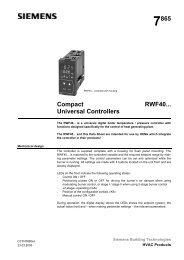
7 422<br />
<strong>Burner</strong> <strong>controls</strong><br />
<strong>LMG</strong>...<br />
<strong>Burner</strong> <strong>controls</strong> for the supervision of 1- or 2-stage gas or forced draft gas / oil<br />
burners of small to medium capacity (typically up to 350 kW) in intermittent operation.<br />
The <strong>LMG</strong>… and this Data Sheet are intended for OEMs which integrate the burner<br />
<strong>controls</strong> in their products.<br />
Use<br />
<strong>LMG</strong>... are designed for the startup and supervision of 1- or 2-stage gas or forced draft<br />
gas / oil burners in intermittent operation. The flame is supervised with an ionization<br />
probe or a UV flame detector QRA…. (with ancillary unit AGQ2 …A27). <strong>LMG</strong>21... /<br />
<strong>LMG</strong>22... in the same housing replace burner <strong>controls</strong> LGB21... / LGB22... (refer to<br />
«Type summary») and – with the help of the relevant adapters – burner <strong>controls</strong> LFI7...<br />
and LFM1... (refer to «Ordering»).<br />
Application-specific<br />
features<br />
- Detection of undervoltages<br />
- Air pressure supervision with functional check of the air pressure switch during<br />
startup and operation (only <strong>LMG</strong>2...)<br />
- Electrical remote reset<br />
- Display of error code and flame signal by signal lamps in the lockout reset button<br />
- Accurate control sequence thanks to digital signal processing<br />
CC1N<strong>7422</strong>en<br />
21.12.2004<br />
Siemens Building Technologies<br />
HVAC Products
Warning notes<br />
To avoid injury to persons, damage to property or the environment, the following<br />
warning notes should be observed!<br />
Do not open, interfere with or modify the unit!<br />
• All activities (mounting, installation and service work, etc.) must be carried out by<br />
qualified staff<br />
• Before performing any wiring changes in the connection area of the <strong>LMG</strong>…, completely<br />
isolate the burner control from the mains supply (all-polar disconnection)<br />
• Ensure protection against electric shock hazard by providing adequate protection<br />
for the burner control’s connection terminals<br />
• Check to ensure that wiring is in an orderly state<br />
• Check the connecting lines of the air pressure switch for short-circuits (connection<br />
terminals 3, 6 and 11)<br />
• Press the lockout reset button / operation button only manually (applying a force of<br />
no more than 10 N), without using any tools or pointed objects<br />
• Fall or shock can adversely affect the safety functions. Such units must not be put<br />
into operation, even if they do not exhibit any damage<br />
Engineering notes<br />
• On applications with actuators, the actuator does not deliver a position feedback<br />
signal to the burner control<br />
• The actuator’s running times must be matched to the burner control’s program. An<br />
additional safety check of the burner together with the actuator must be made<br />
Mounting notes<br />
• Ensure that the relevant national safety regulations are complied with<br />
2/18<br />
Siemens Building Technologies<br />
CC1N<strong>7422</strong>en<br />
HVAC Products 21.12.2004
Installation notes<br />
• Always run the high-voltage ignition cables separate from the unit and other cables<br />
while observing the greatest possible distance<br />
• Do not mix up live and neutral conductors<br />
• Install switches, fuses, earthing, etc., in compliance with local regulations<br />
• The connection diagrams shown apply to burner <strong>controls</strong> with an earthed neutral<br />
conductor. In the case of ionization current supervision in networks with non-earthed<br />
neutral conductor, terminal 2 must be connected to the earth conductor via an RC<br />
unit (part no. ARC 4 668 90660). It must be made certain that local regulations are<br />
complied with (e.g. protection against electric shock hazard) since AC 230 V / 50 Hz<br />
mains voltage produces peak leakage currents of 2.7 mA<br />
• Make certain that the maximum permissible current rating of the connection terminals<br />
will not be exceeded<br />
• Do not feed external mains voltage to the control outputs of the burner control.<br />
When testing the devices controlled by the <strong>LMG</strong>... (fuel valves, etc.), the burner control<br />
must never be plugged in<br />
• In the case of burners with no fan motor, an AGK25 must be connected to terminal<br />
3 of the unit, or else the burner cannot reliably be started up<br />
• For safety reasons, feed the neutral conductor to terminal 2. As shown below, the<br />
burner components (fan, ignition transformer and gas valves) must be connected to<br />
the neutral distributor. The connection between neutral distributor and terminal 2 is<br />
prewired in the base of the unit<br />
Example<br />
2 3 7 4 5<br />
M Z<br />
BV2<br />
BV1<br />
Legend<br />
BV...<br />
M<br />
Z<br />
Fuel valve<br />
Fan motor<br />
Ignition transformer<br />
N<br />
<strong>7422</strong>a01/0300<br />
Correct wiring of neutral conductors<br />
Electrical connection of flame detector<br />
It is important to achieve practically disturbance- and loss-free signal transmission:<br />
• Never run the detector cable together with other cables<br />
– Line capacitance reduces the magnitude of the flame signal<br />
– Use a separate cable<br />
• Observe the permissible length of the detector cables (refer to «Technical data»)<br />
• The ionization probe is not protected against electric shock hazard<br />
• Locate the ignition electrode and ionization probe such that the ignition spark cannot<br />
arc over to the ionization probe (risk of electrical overloads) and that it cannot<br />
adversely affect the supervision of ionization<br />
• Insulation resistance<br />
– Must be a minimum of 50 MΩ between ionization probe and ground<br />
– Soiled detector holders reduce the insulation resistance, thus supporting creepage<br />
currents<br />
• Earth the burner in compliance with the relevant regulations; earthing the boiler<br />
alone does not suffice<br />
3/18<br />
Siemens Building Technologies<br />
CC1N<strong>7422</strong>en<br />
HVAC Products 21.12.2004
Commissioning notes<br />
• Prior to commissioning, check to ensure that wiring is in an orderly state<br />
• When commissioning the plant or when doing maintenance work, make the following<br />
safety checks:<br />
Safety check<br />
a) <strong>Burner</strong> startup with open-circuit to the ionization<br />
probe<br />
b) <strong>Burner</strong> operation with simulated loss of<br />
flame; for that purpose, cut off the gas supply<br />
c) <strong>Burner</strong> operation with simulated air pressure<br />
failure (not with atmospheric burners)<br />
Anticipated response<br />
Lockout at the end of «TSA»<br />
Immediate lockout<br />
Only with<br />
<strong>LMG</strong>25.../<strong>LMG</strong>49.031...:<br />
Restart followed by lockout<br />
at the end of «TSA»<br />
Immediate lockout<br />
Standards and certificates<br />
Conformity to EEC directives<br />
- Electromagnetic compatibility EMC (immunity)<br />
- Directive for gas-fired appliances<br />
- Low-voltage directive<br />
89 / 336 EEC<br />
90 / 396 EEC<br />
73 / 23 EEC<br />
ISO 9001: 2000<br />
Cert. 00739<br />
ISO 14001: 1996<br />
Cert. 38233<br />
Type reference<br />
<strong>LMG</strong>21.130B27 x x x x<br />
<strong>LMG</strong>21.230B27 x x x x<br />
<strong>LMG</strong>21.330B27 x x x x<br />
<strong>LMG</strong>21.350B27 x x x x<br />
<strong>LMG</strong>21.530B27 x x x ---<br />
<strong>LMG</strong>21.550B27 x x x x<br />
<strong>LMG</strong>22.130B27 x x x x<br />
<strong>LMG</strong>22.230B27 x x x x<br />
<strong>LMG</strong>22.233B27 x x x x<br />
<strong>LMG</strong>22.330B27 x x x x<br />
<strong>LMG</strong>25.230B27 x x x x<br />
<strong>LMG</strong>25.330B27 x x x x<br />
<strong>LMG</strong>25.350B27 x x x x<br />
<strong>LMG</strong>49.030B27 --- --- x ---<br />
<strong>LMG</strong>49.031B27 --- --- x ---<br />
• Identification code to EN 298<br />
- <strong>LMG</strong>21... / <strong>LMG</strong>22... F T L L X N<br />
- <strong>LMG</strong>25... F T C L X N<br />
- <strong>LMG</strong>49... A T L L X N<br />
Service notes<br />
• Every time a unit has been replaced, check to ensure that wiring is in an orderly<br />
state and make the safety checks as specified in «Commissioning notes»<br />
• Use service adapter KF8872 for short periods of time only<br />
4/18<br />
Siemens Building Technologies<br />
CC1N<strong>7422</strong>en<br />
HVAC Products 21.12.2004
Disposal notes<br />
The unit contains electrical and electronic components and may not be disposed of<br />
together with domestic waste.<br />
Local and currently valid legislation must be observed.<br />
Mechanical design<br />
<strong>LMG</strong>...<br />
Versions<br />
• Units of plug-in design like their predecessor types LGB2… (refer to «Dimensions»)<br />
• Housing made of impact-proof and heat-resistant plastic<br />
• The housing accommodates:<br />
– The microcontroller with the PCB relay for load control<br />
– The electronic flame signal amplifier (ionization)<br />
– The lockout reset button with the integrated red signal lamp and the green flame<br />
signal lamp<br />
• <strong>LMG</strong>21... / <strong>LMG</strong>22... <strong>Burner</strong> capacity unlimited (thermal output on startup<br />
≤ 120 kW)<br />
Lockout in the event of loss of flame during operation<br />
• <strong>LMG</strong>25... <strong>Burner</strong> capacity ≤ 120 kW<br />
3 repetitions in the event of loss of flame during operation<br />
• <strong>LMG</strong>49.030B27 Lockout in the event of loss of flame during operation<br />
• <strong>LMG</strong>49.031B27 1 repetition in the event of loss of flame during operation<br />
5/18<br />
Siemens Building Technologies<br />
CC1N<strong>7422</strong>en<br />
HVAC Products 21.12.2004
Type summary<br />
The type references given below refer to the <strong>LMG</strong>… with no plug-in base and with no flame detector.<br />
For ordering information on the plug-in bases and other accessories, refer to «Ordering».<br />
Type of flame detector Type reference of<br />
burner control<br />
tw<br />
min.<br />
¹)<br />
t1<br />
min.<br />
TSA<br />
max.<br />
t3n<br />
approx.<br />
t3<br />
approx.<br />
t4<br />
approx.<br />
t10<br />
min.<br />
¹)<br />
t11<br />
max.<br />
²)<br />
t12<br />
max.<br />
²)<br />
Behavior in the event<br />
of loss of flame during<br />
operation<br />
<strong>Burner</strong> <strong>controls</strong> for prepurging with low-fire air volume, without actuator control<br />
Ionization probe (ION) <strong>LMG</strong>21.130B27 ³) 2.5 s 7 s 3 s 2 s 2 s 8 s 5 s --- --- Lockout<br />
or UV flame detector <strong>LMG</strong>21.230B27 4) 2.5 s 20 s 3 s 2 s 2 s 8 s 5 s --- --- Lockout<br />
QRA…. (with ancillary <strong>LMG</strong>21.330B27 4) 2.5 s 30 s 3 s 2 s 2 s 8 s 5 s --- --- Lockout<br />
unit AGQ2 …A27) <strong>LMG</strong>21.350B27 4) 2.5 s 30 s 5 s 4 s 2 s 10 s 5 s --- --- Lockout<br />
<strong>LMG</strong>21.530B27 2.5 s 50 s 3 s 2 s 2 s 8 s 5 s --- --- Lockout<br />
<strong>LMG</strong>21.550B27 4) 2.5 s 50 s 5 s 4 s 2 s 10 s 5 s --- --- Lockout<br />
<strong>Burner</strong> <strong>controls</strong> for prepurging with nominal air volume, with actuator control<br />
Ionization probe (ION) <strong>LMG</strong>22.130B27 ³) 2.5 s 7 s 3 s 2 s 3 s 8 s 3 s 12 s 12 s Lockout<br />
or UV flame detector <strong>LMG</strong>22.230B27 4) 2.5 s 20 s 3 s 2 s 3 s 8 s 3 s 16.5 s 16.5 s Lockout<br />
QRA…. (with ancillary <strong>LMG</strong>22.233B27 2.5 s 20 s 3 s 2 s 3 s 8 s 3 s 30 s 30 s Lockout<br />
unit AGQ2 …A27) <strong>LMG</strong>22.330B27 4) 2.5 s 30 s 3 s 2 s 3 s 8 s 3 s 12 s 11 s Lockout<br />
<strong>Burner</strong> <strong>controls</strong> for prepurging with low-fire air volume, without actuator<br />
Ionization probe (ION) <strong>LMG</strong>25.230B27 2.5 s 20 s 3 s 2 s 2 s 8 s 5 s --- --- Max. 3 repetitions<br />
or UV flame detector <strong>LMG</strong>25.330B27 2.5 s 30 s 3 s 2 s 2 s 8 s 5 s --- --- Max. 3 repetitions<br />
QRA…. (with ancillary <strong>LMG</strong>25.350B27 2.5 s 30 s 5 s 4 s 2 s 10 s 5 s --- --- Max. 3 repetitions<br />
unit AGQ2 …A27)<br />
<strong>Burner</strong> <strong>controls</strong> for atmospheric burners<br />
Ionization probe (ION) <strong>LMG</strong>49.030B27 5) 3.5 s --- 3 s 2 s 0.5 s 0.5 s --- --- --- Lockout<br />
or UV flame detector<br />
QRA…. (with ancillary<br />
unit AGQ2 …A27)<br />
<strong>LMG</strong>49.031B27 3.5 s --- 3 s 2 s 0.5 s 1 s --- --- --- Max. 1 repetition<br />
Legend<br />
TSA Ignition safety time t10 Specified time for air pressure signal<br />
tw Waiting time t11 Programmed opening time for actuator «SA»<br />
t1 Prepurge time t12 Programmed closing time for actuator «SA»<br />
t3 Preignition time<br />
t3n Postignition time<br />
t4 Interval between release of «BV1» and release<br />
of «BV2»<br />
1) Max. 65 s 3) Also suited for use with flash-steam generators<br />
2) Max. running time available for actuators «SA»; 4) Also suited for use with direct fired air heaters<br />
the actuator’s running time must be shorter 5) Unit without «LP» supervision, for burners without fan<br />
up to 120 kW<br />
6/18<br />
Siemens Building Technologies<br />
CC1N<strong>7422</strong>en<br />
HVAC Products 21.12.2004
Ordering<br />
<strong>Burner</strong> control (without plug-in base)<br />
Connection accessories for small burner <strong>controls</strong><br />
- Plug-in base AGK11...<br />
- Cable holders AGK65..., AGK66, and AGK67...<br />
- Cable strain relief elements for AGK67...<br />
Connection accessories for small burner <strong>controls</strong><br />
- Plug-in base AGK13...<br />
- Plug-in housing AGK56...<br />
- Cover AGK68...<br />
refer to «Type summary»<br />
refer to Data Sheet N7201<br />
refer to Data Sheet N7203<br />
Flame detectors<br />
- Ionization probe supplied by thirds<br />
- UV detectors QRA... refer to Data Sheet N7712<br />
Actuators SQN3...<br />
Actuators SQN7...<br />
Actuators SQN9...<br />
refer to Data Sheet N7808<br />
refer to Data Sheet N7804<br />
refer to Data Sheet N7806<br />
Pedestal (empty housing)<br />
For increasing the height to that of the LFM... or LFI7... (refer to «Dimensions»)<br />
AGK21<br />
RC unit ARC 4 668 9066 0<br />
For supervising the ionization current in networks with non-earthed neutral conductor<br />
PTC resistor (AC 230 V)<br />
For producing a burden on terminal 3 (on burners with no fan motor,<br />
e.g. atmospheric gas burners)<br />
AGK25<br />
Ancillary unit for UV supervision<br />
- Cable length 500 mm AGQ2.1A27<br />
- Cable length 300 mm AGQ2.2A27<br />
Can be fitted under the plug-in base (for size, refer to «Dimensions»)<br />
Test adapter<br />
KF8872<br />
- For checking the functioning of the burner on the plant<br />
- Functional check with the signal lamps<br />
Note: With no load on the output terminals, the respective signal lamp may light up<br />
- Detector current measurement with jacks of 4 mm diameter<br />
Adapters / replacement types<br />
No rewiring required<br />
New type of burner control Type of adapter Type of predecessor unit<br />
<strong>LMG</strong>21... with adapter KF8853-K LFI7...<br />
KF8880 ¹)<br />
LFM1... / LFM1...-F<br />
<strong>LMG</strong>2... with adapter KF8853-K LFI7...<br />
KF8880 ¹)<br />
LFM1...<br />
¹) Not for use with atmospheric burners!<br />
For UV supervision, AGQ2... with additional external wiring is also required.<br />
7/18<br />
Siemens Building Technologies<br />
CC1N<strong>7422</strong>en<br />
HVAC Products 21.12.2004
Technical data<br />
General unit data<br />
Environmental<br />
conditions<br />
Mains voltage AC 230 V +10/−15 %<br />
Mains frequency 50...60 Hz ±6 %<br />
<strong>Power</strong> consumption<br />
12 VA<br />
Primary fuse<br />
max. 10 A (slow)<br />
Built-in fuse T6.3H250V to DIN 60 127<br />
Perm. mounting position<br />
optional<br />
Input current at terminal 12<br />
max. 5 A<br />
Weight<br />
approx. 160 g<br />
Degree of protection<br />
IP 40, to be ensured through mounting<br />
Perm. cable length terminal 1<br />
max. 1 m at 100 pF / m<br />
(max. 3 m at 15 pF / m)<br />
Perm. cable length terminals 8 and 10 max. 20 m at 100 pF / m<br />
Perm. cable length other terminals max. 3 m at 100 pF / m<br />
Storage DIN EN 60721-3-1<br />
Climatic conditions<br />
class 1K3<br />
Mechanical conditions<br />
class 1M2<br />
Temperature range -20...+60 °C<br />
Humidity<br />
< 95 % r.h.<br />
Transport DIN EN 60 721-3-2<br />
Climatic conditions<br />
class 2K3<br />
Mechanical conditions<br />
class 2M2<br />
Temperature range -20...+60 °C<br />
Humidity<br />
< 95 % r.h.<br />
Operation DIN EN 60 721-3-3<br />
Climatic conditions<br />
class 3K3<br />
Mechanical conditions<br />
class 3M2<br />
Temperature range -20...+60 °C<br />
Humidity<br />
< 95 % r.h.<br />
Condensation, formation of ice and ingress of water are not permitted!<br />
Perm. amperage At cosϕ ≥ 0.6 At cosϕ = 1<br />
- Terminal 3 Max. 2.7 A (15 A during max. 0.5 s) Max. 3 A<br />
- Terminals 4, 5 and 7 Max. 1.7 A Max. 2 A<br />
- Terminal 10 Max. 1 A Max. 1 A<br />
Flame supervision<br />
with ionization probe<br />
Note<br />
At mains voltage<br />
UN = AC 230 V<br />
Detector voltage across terminals 1 and 2 or ground<br />
≤ UN<br />
(AC voltmeter, Ri ≥ 10 MΩ)<br />
Switching thresholds (limit values)<br />
Switching on (flame on) (DC ammeter, Ri ≤ 5 kΩ)<br />
≥ 2 µA<br />
Switching off (flame off) (DC ammeter, Ri ≤ 5 kΩ)<br />
≤ 1.6 µA<br />
Detector current required for reliable operation ≥ 3 µA<br />
Possible detector current during operation Max. 40 µA<br />
Short-circuit current across terminals 1 and 2 or ground<br />
Max. 100 µA<br />
(AC ammeter, Ri ≤ 5 kΩ)<br />
With the same quality of flame, the detector current with the <strong>LMG</strong>… may be lower<br />
than that with the LGB2….<br />
Flame supervision is accomplished by making use of the conductivity and rectifying<br />
effect of the flame.<br />
The flame signal amplifier only responds to the DC current component of the flame signal.<br />
A short-circuit between ionization probe and ground causes the burner to initiate lockout.<br />
8/18<br />
Siemens Building Technologies<br />
CC1N<strong>7422</strong>en<br />
HVAC Products 21.12.2004
Technical data (cont´d)<br />
Measuring circuit<br />
<strong>LMG</strong>... 1<br />
<strong>7422</strong>v01/0703<br />
M<br />
+ -<br />
+<br />
C<br />
ION<br />
Legend<br />
C Electrolytic capacitor 100...470 µF; DC 10...25 V<br />
ION Ionization probe<br />
M Microammeter, Ri max. 5,000 Ω<br />
For detector currents, refer to «Technical data».<br />
Flame supervision<br />
with AGQ2...A27 and<br />
UV detector QRA...<br />
Mains voltage AC 230 V +10 % / -15 %<br />
Mains frequency 50...60 Hz ±6 %<br />
Perm. cable length from QRA... to max. 20 m<br />
AGQ2...A27 (lay separate cable)<br />
Perm. cable length from<br />
max. 2 m<br />
AGQ2...A27 to <strong>LMG</strong>...<br />
Weight of AGQ2...A27<br />
approx. 140 g<br />
Perm. mounting position<br />
optional<br />
Degree of protection<br />
IP 40, to be ensured through mounting<br />
<strong>Power</strong> consumption<br />
4.5 VA<br />
At mains voltage UN<br />
AC 220 V AC 240 V<br />
Detector voltage at QRA... (with no load)<br />
Until the end of «t10» and after controlled shutdown DC 400 V DC 400 V<br />
From the start of «t1» DC 300 V DC 300 V<br />
Detector voltage<br />
Load by DC measuring instrument Ri > 10 MΩ<br />
Until the end of «t10» and after controlled shutdown DC 380 V DC 380 V<br />
From the start of «t1» DC 280 V DC 280 V<br />
DC current detector signals with UV detector Min. required Max. possible<br />
QRA...<br />
Measurement at the UV detector 200 µA 500 µA<br />
9/18<br />
Siemens Building Technologies<br />
CC1N<strong>7422</strong>en<br />
HVAC Products 21.12.2004
Technical data (cont´d)<br />
Ancillary unit<br />
AGQ2...A27<br />
In connection with burner <strong>controls</strong> <strong>LMG</strong>..., use of UV ancillary unit AGQ2...A27 is mandatory.<br />
Using circuitry (A) or (B), the quench test on aging UV detectors can be made in 2 different<br />
ways:<br />
1. (A) Operation with a permanent line.<br />
UV test with a higher supply voltage across the UV cell on startup and after the<br />
controlled shutdown.<br />
2. (B) Operation with a controlled line.<br />
UV test with a higher supply voltage only on startup during the interval between<br />
controlled startup and air pressure signal.<br />
- No voltage at UV cell after the controlled shutdown<br />
- No full substitute for mode (A) described above since an aged UV cell<br />
can regenerate itself<br />
Connection diagram<br />
Measuring circuit for measuring the UV<br />
detector current<br />
GP/SB<br />
R/W<br />
L<br />
L<br />
N<br />
<strong>LMG</strong>...<br />
12 2 11 1<br />
(B)<br />
(A)<br />
<strong>7422</strong>a02/0602<br />
br bl rt sw AGQ2...A27<br />
sw bl<br />
AGQ2...A27<br />
br bl rt sw<br />
sw bl<br />
QRA<br />
<strong>7422</strong>a21/0702<br />
QRA<br />
+<br />
-<br />
Measurement made at the UV detector<br />
Legend<br />
C Electrolytic capacitor 100...470 µF; DC 10...25 V bl Blue<br />
M Microammeter Ri max. 5,000 Ω br Brown<br />
QRA... UV detector gr Grey<br />
GP Gas pressure switch rt Red<br />
SB Safety limit thermostat sw Black<br />
R Control thermostat or pressurestat<br />
W Limit thermostat or pressure switch<br />
10/18<br />
Siemens Building Technologies<br />
CC1N<strong>7422</strong>en<br />
HVAC Products 21.12.2004
Function<br />
<strong>LMG</strong>21...<br />
Legend<br />
A B B´ C D<br />
SB / R / W / GP<br />
AL<br />
M<br />
Z<br />
BV1<br />
BV2<br />
12<br />
10<br />
3<br />
7<br />
4<br />
5<br />
LP<br />
11<br />
FS<br />
EK2<br />
1<br />
8<br />
tw t10 t1 t3 t3n<br />
TSA<br />
400 ms<br />
t4<br />
<strong>LMG</strong>22...<br />
A B B´ C D<br />
SB / R / W / GP<br />
AL<br />
I<br />
LK<br />
M<br />
Z<br />
<strong>7422</strong>d01/0700<br />
12<br />
10<br />
3<br />
7<br />
A<br />
B-B´<br />
C<br />
C-D<br />
D<br />
AL<br />
BV...<br />
EK2<br />
FS<br />
GP<br />
LP<br />
LR<br />
M<br />
R<br />
SA<br />
SB<br />
W<br />
Z<br />
Start command (switching on by «R»)<br />
Interval for establishment of flame<br />
Operating position of burner reached<br />
<strong>Burner</strong> operation (generation of heat)<br />
Controlled shutdown by «R»<br />
• <strong>Burner</strong> will immediately be shut down<br />
• <strong>Burner</strong> control will immediately be ready for a new<br />
startup<br />
Error message (alarm)<br />
Fuel valve<br />
Remote reset button<br />
Flame signal<br />
Gas pressure switch<br />
Air pressure switch<br />
Load controller<br />
Fan motor<br />
Control thermostat or pressurestat<br />
Actuator<br />
Safety limit thermostat<br />
Limit thermostat or pressure switch<br />
Ignition transformer<br />
SA<br />
BV1<br />
9<br />
4<br />
I<br />
Cam I actuator<br />
(LR) BV2<br />
LP<br />
FS<br />
EK2<br />
<strong>LMG</strong>49...<br />
SB / R / W / GP<br />
AL<br />
Z<br />
5<br />
11<br />
1<br />
8<br />
t10<br />
tw t1 t3 t3n 400 ms<br />
t12<br />
TSA t4<br />
<strong>7422</strong>d03/0700<br />
t11<br />
A B B´ C D<br />
12<br />
10<br />
7<br />
<strong>7422</strong>d06/0301<br />
t1<br />
t3<br />
t3n<br />
t4<br />
t10<br />
t11<br />
t12<br />
TSA<br />
tw<br />
Prepurge time<br />
Preignition time<br />
Postignition time<br />
Interval between establishment of flame and release of «BV2»<br />
Specified time for air pressure signal<br />
Programmed opening time for actuator «SA»<br />
Programmed closing time for actuator «SA»<br />
Ignition safety time<br />
Waiting time<br />
BV1<br />
4<br />
BV2<br />
5<br />
FS<br />
1<br />
EK2<br />
tw + t1<br />
t3<br />
t3n<br />
TSA<br />
400 ms<br />
t4<br />
8<br />
11/18<br />
Siemens Building Technologies<br />
CC1N<strong>7422</strong>en<br />
HVAC Products 21.12.2004
Function (cont´d)<br />
Prerequisites for<br />
startup<br />
Undervoltage<br />
Controlled intermittent<br />
operation<br />
Reversed polarity<br />
protection<br />
Control program in the<br />
event of fault<br />
Lockout<br />
Resetting the <strong>LMG</strong>...<br />
• <strong>Burner</strong> control is reset<br />
• All contacts in the line are closed<br />
• Fan motor «M» or AGK25 is connected<br />
• Air pressure switch «LP» is in the normal position<br />
• No undervoltage<br />
• Fuel valve «BV1» is connected<br />
Safety shutdown is the event<br />
- mains voltage is lower than AC 180 V (typically)<br />
- a restart is made when mains voltage exceeds AC 195 V<br />
After no more than 24 hours of continuous operation, the burner control will initiate<br />
automatic safety shutdown followed by a restart.<br />
If the connections of line (terminal 12) and the neutral conductor (terminal 2) have been<br />
mixed up, the burner control will initiate lockout at the end of «TSA».<br />
• If a fault occurs, all outputs will immediately be deactivated (< 1 second)<br />
• On restoration of power, a restart will be made with the full control sequence<br />
• If mains voltage drops below the undervoltage threshold (for threshold, refer to<br />
«Functions»), a restart will be made with the full control sequence<br />
• If there is a premature faulty flame signal during «t1», the burner control will initiate<br />
lockout<br />
• If the contacts of the air pressure switch «LP» have welded in their working position,<br />
startup will be prevented and, after 65 seconds, lockout initiated<br />
• If there is no air pressure on completion of «t10», the burner control will initiate<br />
lockout<br />
• If the burner does not ignite during «TSA», lockout will be initiated<br />
• If the flame is lost during operation:<br />
→ <strong>LMG</strong>21... / <strong>LMG</strong>22... / <strong>LMG</strong>49.030B27<br />
lockout<br />
→ <strong>LMG</strong>25...<br />
3 repetitions<br />
→ <strong>LMG</strong>49.031B27<br />
1 repetition<br />
Lockout cannot be changed and takes place 10 seconds after safety shutdown.<br />
A mains voltage failure during that period a time will lead to a restart.<br />
Whenever lockout occurs, the burner control can immediately be reset.<br />
Press lockout reset button and keep it depressed for 0.5... 3 seconds.<br />
The <strong>LMG</strong>... can be reset only when all contacts in the line are closed and when there is<br />
no undervoltage.<br />
12/18<br />
Siemens Building Technologies<br />
CC1N<strong>7422</strong>en<br />
HVAC Products 21.12.2004
Connection diagram<br />
<strong>LMG</strong>21... / <strong>LMG</strong>25...<br />
<strong>LMG</strong>21.../25...<br />
12 2 10 8 3 6 11 7 9 4 5 1<br />
1)<br />
ION<br />
R/W<br />
1) Wire link required only with the LGB21..., not with the <strong>LMG</strong>21... /<br />
<strong>LMG</strong>25...<br />
GP/SB<br />
HS<br />
0 I<br />
L<br />
N<br />
Si<br />
AL<br />
EK2<br />
M<br />
LP<br />
Z<br />
BV1<br />
BV2<br />
<strong>7422</strong>a03/0404<br />
Application examples<br />
<strong>LMG</strong>2...<br />
Control of actuators of 2-stage or 2-stage modulating burners.<br />
Controlled pre-purging «t1» with low-fire air volume. Same low-fire actuator<br />
position during startup and operation.<br />
For information about actuators «SA»:<br />
SQN3... refer to Data Sheet N7808<br />
SQN7… refer to Data Sheet N7804<br />
SQN9... refer to Data Sheet N7806<br />
L<br />
5<br />
LR<br />
ON/OFF<br />
12 4<br />
SA<br />
SB/R/W<br />
<strong>7422</strong>a04/0300<br />
BV1<br />
RV<br />
BV2<br />
<strong>LMG</strong>21.../25...<br />
12 2 10 8 3 6 11 9 7 4 5 1<br />
(*)<br />
EK2<br />
ION<br />
LP<br />
AL M<br />
Z<br />
BV1<br />
GP/SB<br />
<strong>LMG</strong>21.../25...<br />
12 2 10 8 3 6 11 9 7 4 5 1<br />
AL<br />
EK2<br />
M<br />
LP<br />
GP/<br />
SB<br />
Z<br />
BV1<br />
ION<br />
R/W<br />
LR<br />
R/W<br />
LR<br />
HS<br />
0 I<br />
N<br />
L<br />
Si<br />
BV2<br />
(*)<br />
*<br />
N 1 2 6 7 5 4 3<br />
b1 b2 B<br />
a<br />
a3<br />
II<br />
III<br />
a b<br />
b<br />
MS<br />
I<br />
a b<br />
a2<br />
a<br />
IV<br />
b<br />
A<br />
V<br />
a b<br />
<strong>7422</strong>a05/0404<br />
RV<br />
LK<br />
LKP<br />
NL<br />
KL<br />
IV<br />
III<br />
Zu<br />
II<br />
SQN3...121... / 2-stage control<br />
* Note:<br />
With 2-stage modulating burners (with gas regulation damper «RV»),<br />
«BV2» and the dotted connection between terminals (*) are not<br />
required.<br />
t1<br />
I<br />
IV IV<br />
III<br />
<strong>7422</strong>d04/0300<br />
HS<br />
0 I N N 1 2 5 3 6 4<br />
Si<br />
K2<br />
N L<br />
+<br />
IV<br />
III<br />
t<br />
SA<br />
a b<br />
D<br />
a b<br />
- +<br />
K1<br />
C3<br />
C31<br />
II I<br />
V<br />
MS<br />
a b a b R32 R1 a b<br />
SQN91.140... / 2-stage control<br />
BV2<br />
<strong>7422</strong>a06/0404<br />
LK<br />
<strong>LMG</strong>21.../25...<br />
12<br />
2 10 8 3<br />
6 11 7 4<br />
5 1<br />
LP<br />
ION<br />
EK2<br />
Z<br />
AL<br />
M<br />
GP/<br />
SB<br />
BV1<br />
R/W<br />
LR<br />
BV2<br />
HS<br />
N 8 4<br />
1<br />
5 3 2 7 6<br />
0<br />
I<br />
N<br />
L<br />
Si<br />
a1<br />
c1<br />
b2<br />
LKP<br />
NL<br />
I<br />
I<br />
B<br />
A<br />
b1<br />
I<br />
M<br />
a2<br />
II III<br />
C<br />
IV<br />
<strong>7422</strong>a07/0404<br />
KL<br />
zu<br />
II<br />
III<br />
t1<br />
TSA<br />
t4<br />
IV<br />
IV<br />
III<br />
t<br />
SQN7...244 / 2-stage control<br />
13/18<br />
Siemens Building Technologies<br />
CC1N<strong>7422</strong>en<br />
HVAC Products 21.12.2004
Connection diagram (cont´d)<br />
<strong>LMG</strong>22...<br />
<strong>LMG</strong>22... / <strong>LMG</strong>29...<br />
12 2 10 8 3 6 11 7 4 5 9 1<br />
R/W<br />
SA<br />
ION<br />
GP/SB<br />
HS<br />
0 I<br />
L<br />
N<br />
Si<br />
AL<br />
EK2<br />
M<br />
LP<br />
Z<br />
BV1<br />
BV2<br />
<strong>7422</strong>a08/0404<br />
Application examples<br />
12<br />
<strong>LMG</strong>2...<br />
5<br />
9<br />
4<br />
<strong>7422</strong>a09/0300<br />
Control of actuators of 2-stage or 2-stage modulating burners.<br />
Controlled prepurging «t1» with nominal load air volume.<br />
LR<br />
SA<br />
RV<br />
For information about actuators «SA»:<br />
SQN3... refer to Data Sheet N7808<br />
SQN7... refer to Data Sheet N7804<br />
SQN9... refer to Data Sheet N7806<br />
L<br />
SB/R/W<br />
BV1<br />
BV2<br />
<strong>LMG</strong>22... / <strong>LMG</strong>29...<br />
12 2 10 8 3 6 11 9 5 7 4 1<br />
<strong>LMG</strong>22... / <strong>LMG</strong>29...<br />
12 2 10 8 3 6 11 9 5 7 4 1<br />
GP<br />
R/W<br />
AL<br />
EK2<br />
M<br />
LP<br />
Z<br />
S1)<br />
LR<br />
BV1<br />
ION<br />
R/W<br />
AL<br />
EK2<br />
LP<br />
LR<br />
Z<br />
BV1<br />
ION<br />
GP/SB<br />
M<br />
HS<br />
0 I<br />
BV2<br />
SB<br />
N 1 8 2 7 5 6 3 4 9 2)<br />
R1<br />
Si<br />
B b1 b2<br />
N L<br />
A a1 a2<br />
R3<br />
M<br />
LK<br />
I<br />
II III V 1)<br />
5<br />
RV<br />
*<br />
*<br />
<strong>7422</strong>a22/0404<br />
LKP<br />
t1<br />
NL<br />
I<br />
KL<br />
III<br />
Zu<br />
II<br />
SQN3...151... or SQN3...251...<br />
* Note:<br />
With 2-stage modulating burners (with gas regulation damper<br />
«RV»), «BV2» and the dotted connection between terminals (*)<br />
are not required.<br />
t4<br />
TSA<br />
III<br />
<strong>7422</strong>d05/0300<br />
t<br />
HS<br />
0 I<br />
Si<br />
N L<br />
SA<br />
6 8 10 2 1 3 7 9<br />
R3<br />
R1<br />
K2<br />
C2<br />
K1<br />
+<br />
D<br />
- +<br />
C3<br />
III RV<br />
R2<br />
I<br />
II<br />
MS<br />
C1<br />
LK<br />
SQN90.220... / 2-stage modulating control<br />
<strong>7422</strong>a11/0404<br />
<strong>LMG</strong>22... / <strong>LMG</strong>29...<br />
<strong>LMG</strong>22... / <strong>LMG</strong>29...<br />
12<br />
2<br />
10<br />
8<br />
3<br />
6 11<br />
5<br />
9<br />
7<br />
4 1<br />
12<br />
2 10 8 3 6 11 9 5 7<br />
4 1<br />
R/W<br />
GP/SB<br />
AL<br />
EK2<br />
LP<br />
M<br />
LR<br />
Z<br />
BV1<br />
ION<br />
R/W<br />
GP/SB<br />
AL<br />
EK2<br />
LP<br />
M<br />
LR<br />
1 2<br />
Z<br />
BV1<br />
ION<br />
BV2<br />
BV2<br />
HS<br />
N 5 4 1 3 2 8 6 7<br />
HS<br />
N 4 5 1<br />
3 2 8 6 7<br />
0<br />
I<br />
N<br />
Si<br />
L<br />
C<br />
a1<br />
A<br />
b1<br />
I<br />
b2<br />
c1<br />
a2<br />
M<br />
II III<br />
B<br />
IV<br />
<strong>7422</strong>a12/0404<br />
LKP<br />
NL I<br />
I<br />
IV<br />
KL<br />
III<br />
zu<br />
II t1 TSA<br />
t4<br />
IV<br />
III<br />
0<br />
I<br />
t<br />
N<br />
Si<br />
L<br />
A<br />
a1<br />
b1<br />
I<br />
M<br />
b2<br />
a2<br />
II III<br />
B<br />
IV<br />
<strong>7422</strong>a13/0404<br />
SQN7...454 / 2-stage control, 1-wire control<br />
SQN7...424 / 2-stage control, 2-wire control<br />
14/18<br />
Siemens Building Technologies<br />
CC1N<strong>7422</strong>en<br />
HVAC Products 21.12.2004
Connection diagram (cont´d)<br />
<strong>LMG</strong>49...<br />
<strong>LMG</strong>49...<br />
12 2 10 8 3 6 11 7 9 4 5 1<br />
ION<br />
R/W<br />
AGK25<br />
GP/SB<br />
HS<br />
0 I<br />
L<br />
N<br />
Si<br />
AL<br />
EK2<br />
Z<br />
BV1<br />
BV2<br />
<strong>7422</strong>a19/0404<br />
Other application examples<br />
<strong>Burner</strong> without fan and without «LP»<br />
2 3 11 6<br />
AGK25<br />
<strong>7422</strong>a15/0300<br />
*<br />
* Note: Different from LGB...<br />
Only for <strong>LMG</strong>21... / <strong>LMG</strong>22... / <strong>LMG</strong>25...<br />
<strong>Burner</strong> with fan control via auxiliary contactor «HS» with<br />
«LP»<br />
GP/SB<br />
R/W<br />
L<br />
N<br />
12 2 3 11 6<br />
M<br />
HS AGK25 LP<br />
<strong>7422</strong>a14/0300<br />
Legend<br />
AGK25... PTC resistor LR Load controller<br />
AL Error message (alarm) M Fan motor<br />
BV... Fuel valve MS Synchronous motor<br />
Dbr... Wire link NL Nominal load<br />
EK2 Remote lockout reset button QRA... UV detector<br />
ION Ionization probe R Control thermostat / pressurestat<br />
FS Flame signal RV Gas regulation damper<br />
GP Gas pressure switch SA Actuator SQN...<br />
HS Auxiliary contactor, relay SB Safety limit thermostat<br />
K1...4 Internal relays Si External fuse<br />
KL Low-fire t Time<br />
LK Air damper W Limit thermostat / pressure switch<br />
LKP Air damper position Z Ignition transformer<br />
LP<br />
Air pressure switch<br />
Operating concept<br />
• <strong>Burner</strong> control has initiated lockout<br />
→ Red signal lamp illuminated<br />
<strong>7422</strong>z01/0300<br />
AL<br />
• <strong>Burner</strong> control in operation<br />
→ Green flame signal lamp<br />
illuminated<br />
• Reset<br />
Press lockout reset button for 0.5...3 s<br />
• Diagnostics of cause of fault<br />
- Wait > 10 s<br />
- Press lockout reset button for > 3 s<br />
- Read blink code of red signal lamp<br />
→ «Error code table»<br />
• Restart<br />
Press lockout reset button for 0.5...3 s<br />
FS<br />
<strong>7422</strong>z02/0300<br />
15/18<br />
Siemens Building Technologies<br />
CC1N<strong>7422</strong>en<br />
HVAC Products 21.12.2004
Diagnostics of cause of fault<br />
FS<br />
Steady on<br />
AL<br />
<strong>7422</strong>z03e/0301<br />
After lockout, the red signal lamp is steady on.<br />
For reading the cause of fault, refer to the blink code given in the following table:<br />
~<br />
Illuminated phase<br />
(waiting time > 10 s)<br />
Press lockout<br />
reset button<br />
for > 3 s<br />
Blink code<br />
Fault Approx. 3 s<br />
<strong>7422</strong>z04e/0902<br />
Off<br />
Blink code<br />
~<br />
Error code table<br />
Blink code<br />
2 blinks<br />
hh<br />
3 blinks<br />
hhh<br />
4 blinks<br />
hhhh<br />
5 blinks<br />
hhhhh<br />
7 blinks<br />
hhhhhhh<br />
8...17 blinks<br />
hhhhhhhh<br />
.................<br />
hhhhhhhhhh<br />
hhhhhhh<br />
18 blinks<br />
hhhhhhhhhh<br />
hhhhhhhh<br />
19 blinks<br />
hhhhhhhhhh<br />
hhhhhhhhh<br />
20 blinks<br />
hhhhhhhhhh<br />
hhhhhhhhhh<br />
Possible cause<br />
• No establishment of flame at the end of «TSA»<br />
- Faulty or soiled ionization probe<br />
- Faulty or soiled fuel valves<br />
- Poor adjustment of burner<br />
• Air pressure switch does not close<br />
- «LP» faulty<br />
- «LP» incorrectly adjusted<br />
- Fan motor does not run<br />
• Air pressure switch does not open or extraneous light<br />
on burner startup<br />
- «LP» faulty<br />
- «LP» incorrectly adjusted<br />
• Extraneous light during prepurging<br />
- Or internal device fault<br />
• Loss of flame during operation<br />
- Poor adjustment of burner<br />
- Faulty or soiled fuel valves<br />
- Short-circuit between ionization probe and ground<br />
• Free<br />
• Air pressure switch opens during prepurging or operation<br />
- «LP» incorrectly adjusted<br />
- 4 times loss of flame during operation (<strong>LMG</strong>25...)<br />
- 2 times loss of flame during operation<br />
(<strong>LMG</strong>49.031...)<br />
• Faulty output contact<br />
- Wiring error<br />
- External power supply on output terminal<br />
• Internal device fault<br />
During the time the cause of fault is diagnosed, the control outputs are deactivated.<br />
- The burner remains shut down<br />
- Exception: Error message «AL» at terminal 10<br />
The burner is switched on only after a reset is made<br />
- Press lockout reset button for 0.5...3 s<br />
16/18<br />
Siemens Building Technologies<br />
CC1N<strong>7422</strong>en<br />
HVAC Products 21.12.2004
Internal diagram<br />
<strong>LMG</strong>21... / <strong>LMG</strong>25...<br />
NT<br />
Control of mircocontroller<br />
EK<br />
RESET<br />
<strong>7422</strong>a17e/0404<br />
AL red<br />
FS green<br />
K4<br />
FSV<br />
R/W/<br />
GP/SB<br />
H<br />
AS<br />
12 2<br />
10<br />
AL<br />
K1<br />
K2<br />
7<br />
Z<br />
3<br />
M<br />
K3<br />
4 5<br />
BV1<br />
BV2<br />
EK2<br />
8 6<br />
11<br />
LP<br />
1<br />
ION<br />
Si<br />
L<br />
N<br />
<strong>LMG</strong>22...<br />
NT<br />
Control of microcontroller<br />
EK<br />
RESET<br />
<strong>7422</strong>a18e/0404<br />
AL red<br />
FS green<br />
K4<br />
FSV<br />
AS<br />
12 2<br />
10<br />
K1<br />
K2<br />
7<br />
3<br />
9<br />
K3<br />
4 5<br />
8 6<br />
11<br />
1<br />
R/W/<br />
GP/SB<br />
H<br />
Si<br />
AL<br />
Z<br />
M<br />
BV1<br />
BV2<br />
LR<br />
EK2<br />
LP<br />
ION<br />
L<br />
SA<br />
N<br />
M<br />
BV2<br />
<strong>LMG</strong>49...<br />
NT<br />
Control of microcontroller<br />
EK<br />
RESET<br />
<strong>7422</strong>a20e/0404<br />
AL red<br />
FS green<br />
K4<br />
FSV<br />
R/W/<br />
GP/SB<br />
AS<br />
12 2<br />
10<br />
AL<br />
K1<br />
K2<br />
7<br />
Z<br />
3<br />
K3<br />
4 5<br />
BV1<br />
BV2<br />
EK2<br />
8 6 11<br />
1<br />
ION<br />
H<br />
Si<br />
L<br />
N<br />
AGK25<br />
Legend<br />
AL Alarm LR Load controller<br />
AS Unit fuse M Fan motor<br />
BV... Fuel valve NT <strong>Power</strong> section<br />
EK... Lockout reset button (built-in) R Control thermostat or pressurestat<br />
FS Flame signal SA Actuator<br />
FSV Flame signal amplifier SB Safety limit thermostat<br />
GP Gas pressure switch Si External fuse<br />
H Main switch W Limit thermostat or pressure switch<br />
ION Ionization probe Z Ignition transformer<br />
LP Air pressure switch<br />
17/18<br />
Siemens Building Technologies<br />
CC1N<strong>7422</strong>en<br />
HVAC Products 21.12.2004
Dimensions<br />
Dimensions in mm<br />
<strong>LMG</strong>...<br />
22<br />
5,5<br />
Plug-in base AGK11... / AGK13...<br />
62,5<br />
<strong>7422</strong>m06/1204<br />
88<br />
91<br />
9<br />
41,5<br />
47<br />
62,5<br />
Ancillary unit<br />
AGQ2...A27<br />
27,5<br />
90,5<br />
60<br />
Type<br />
reference<br />
Dimensions<br />
A B<br />
220 69 6<br />
AGQ2.1A27 500 19<br />
AGQ2.2A27 300 34<br />
18<br />
65,6<br />
4<br />
5,4 5,4<br />
13<br />
<strong>7422</strong>m03/0400<br />
A B 6<br />
18/18<br />
© 2004 Siemens Building Technologies HVAC Products GmbH<br />
Subject to change!<br />
Siemens Building Technologies<br />
CC1N<strong>7422</strong>en<br />
HVAC Products 21.12.2004
Represented By:<br />
POWER EQUIPMENT COMPANY<br />
2011 Williamsburg Road<br />
Richmond, VA 23231<br />
Ph. 804-236-3800<br />
Fx. 804-236-3882<br />
www.peconet.com


