750-333; PROFIBUS DPV1 12 MBd - WAGO
750-333; PROFIBUS DPV1 12 MBd - WAGO
750-333; PROFIBUS DPV1 12 MBd - WAGO

Create successful ePaper yourself
Turn your PDF publications into a flip-book with our unique Google optimized e-Paper software.
0 1 2 3 4 5 6 7 8 9<br />
1<br />
40<br />
<strong>750</strong>-<strong>333</strong><br />
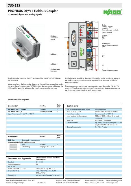
<strong>PROFIBUS</strong> DP/V1 Fieldbus Coupler<br />
<strong>12</strong> Mbaud; digital and analog signals<br />
Fieldbus<br />
connection<br />
D-Sub<br />
Address<br />
ADDRESS<br />
x1<br />
0 91 8<br />
2<br />
7<br />
3<br />
6 5 4<br />
<strong>PROFIBUS</strong><br />
RUN<br />
BF<br />
DIA<br />
BUS<br />
I/O<br />
W<br />
<strong>750</strong>-<strong>333</strong><br />
A<br />
B<br />
01 02<br />
24V 0V<br />
+ +<br />
— —<br />
C<br />
D<br />
Status<br />
voltage supply<br />
-System<br />
-Power jumper contacts<br />
Data Contacts<br />
Supply<br />
24 V<br />
0 V<br />
Supply via<br />
power jumper contacts<br />
24 V<br />
0 V<br />
Address<br />
x10<br />
Configuration<br />
interface<br />
Power jumper contacts<br />
This buscoupler interfaces the I/O modules of the <strong>WAGO</strong>-I/O-SYSTEM to<br />
<strong>PROFIBUS</strong> DP.<br />
When initializing, the buscoupler determines the module structure of the node,<br />
to create the process image in <strong>PROFIBUS</strong>. In order to optimize addresses, the<br />
I/O modules with a bit width smaller than 8 are grouped in one byte.<br />
It is furthermore possible to deactive I/O modules and to modify the image of<br />
the node according to the connected signals without having to modify the<br />
existing application.<br />
The diagnosis concept is based on diagnostics according to the EN 50170<br />
standard. Therefore the programming of modules is not necessary to interpret<br />
the diagnostic information from each manufacturer.<br />
Notice: GSD files required<br />
Pack.<br />
Description<br />
Item No.<br />
Unit<br />
<strong>PROFIBUS</strong> DP/V1 <strong>12</strong><strong>MBd</strong> <strong>750</strong>-<strong>333</strong> 1<br />
<strong>PROFIBUS</strong> DP/V1/T <strong>750</strong>-<strong>333</strong>/025-000 1<br />
Operating temperature -20 °C ... +60 °C<br />
System Data<br />
No. of couplers connected to Master 96 with repeater<br />
Max. no. of I/O points<br />
approx. 6000 (depends on master)<br />
Transmission medium Cu cable acc. to EN 50170<br />
Max. length of fieldbus segment 100 m ... <strong>12</strong>00 m (depends on baud<br />
rate/cable)<br />
Baud rate<br />
9.6 Kbaud ... <strong>12</strong> Mbaud<br />
Transmission time<br />
typ. 1 ms (10 couplers; 32 digital I/Os per<br />
coupler at <strong>12</strong> Mbaud) max. 3.3 ms<br />
Buscoupler connection<br />
1 x D-Sub 9; socket<br />
Pack.<br />
Accessories<br />
Item No.<br />
Unit<br />
GSD files Download: www.wago.com<br />
Miniature WSB Quick marking system<br />
plain 248-501 5<br />
with marking see pages 304 ... 305<br />
(Approvals for product variations<br />
Standards and Approvals upon request)<br />
Standard EN 50170<br />
Conformity marking 1<br />
r UL 508<br />
4 r ANSI/ISA <strong>12</strong>.<strong>12</strong>.01 Class I, Div. 2, Grp. ABCD, T4<br />
4 EN 60079-15 I M2 / II 3 GD Ex nA nL IIC T4<br />
BR-Ex nA II T4<br />
Shipbuilding see "Approvals Overview" in section 1<br />
<strong>WAGO</strong> Kontakttechnik GmbH & Co. KG<br />
Subject to design changes 18.02.2010<br />
Postfach 2880 - D-32385 Minden<br />
Hansastr. 27 - D-32423 Minden<br />
Phone: +49(0)571/887-0<br />
Fax: +49(0)571/887-169<br />
E-Mail: info@wago.com<br />
www.wago.com
1<br />
41<br />
1<br />
FIELDBUS<br />
INTERFACE<br />
1<br />
2<br />
5<br />
6<br />
24 V /0 V<br />
24 V<br />
24 V<br />
0 V<br />
24 V<br />
10 nF<br />
24 V<br />
5 V<br />
5 V<br />
I/O<br />
modules<br />
ELECTRONICS<br />
ELECTRONICS<br />
3<br />
4<br />
7<br />
8<br />
0 V<br />
0 V<br />
10 nF<br />
FIELDBUS<br />
INTERFACE<br />
<strong>750</strong>-<strong>333</strong><br />
Technical Data<br />
Number of I/O modules 63<br />
Fieldbus<br />
Max. input process image<br />
244 bytes<br />
Max. output process image<br />
244 bytes<br />
Configuration<br />
via PC or PLC<br />
Voltage supply 24 V DC (-25 % ... +30 %)<br />
Max. input current (24 V)<br />
500 mA<br />
Efficiency of the power supply 87 %<br />
Internal current consumption (5 V) 200 mA<br />
Total current for I/O modules (5 V) 1800 mA<br />
Isolation<br />
500 V system/supply<br />
Voltage via power jumper contacts 24 V DC (-25 % ... +30 %)<br />
Current via power jumper contacts (max.) 10 A DC<br />
General Specifications<br />
Operating temperature 0 °C ... +55 °C<br />
Wire connection CAGE CLAMP ®<br />
Cross sections 0.08 mm² ... 2.5 mm² / AWG 28 ... 14<br />
Stripped lengths<br />
8 ... 9 mm / 0.33 in<br />
Dimensions (mm) W x H x L 51 x 65 x 100<br />
Height from upper-edge of DIN 35 rail<br />
Weight<br />
182 g<br />
Storage temperature -25 °C ... +85 °C<br />
Relative air humidity (no condensation) 95 %<br />
Vibration resistance acc. to IEC 60068-2-6<br />
Shock resistance acc. to IEC 60068-2-27<br />
Degree of protection<br />
IP20<br />
EMC 1-Immunity to interference acc. to EN 61000-6-2 (2005)<br />
EMC 1-Emission of interference acc. to EN 61000-6-4 (2007)<br />
EMC marine applications - Immunity to<br />
interference acc. to Germanischer Lloyd (2003)<br />
EMC marine applications - Emission of<br />
interference acc. to Germanischer Lloyd (2003)