Download this Article as PDF-File
Download this Article as PDF-File
Download this Article as PDF-File

You also want an ePaper? Increase the reach of your titles
YUMPU automatically turns print PDFs into web optimized ePapers that Google loves.
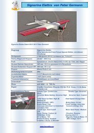
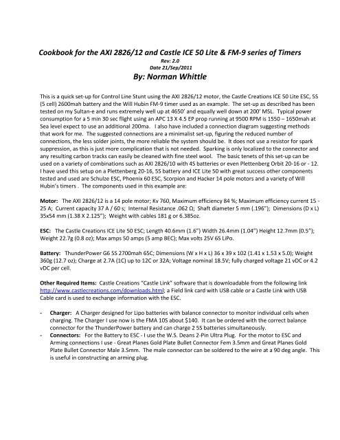
Cookbook for the AXI 2826/12 and C<strong>as</strong>tle ICE 50 Lite & FM-9 series of Timers<br />
Rev: 2.0<br />
Date 21/Sep/2011<br />
By: Norman Whittle<br />
This is a quick set-up for Control Line Stunt using the AXI 2826/12 motor, the C<strong>as</strong>tle Creations ICE 50 Lite ESC, 5S<br />
(5 cell) 2600mah battery and the Will Hubin FM-9 timer used <strong>as</strong> an example. The set-up <strong>as</strong> described h<strong>as</strong> been<br />
tested on my Sultan-e and runs extremely well up at 4650’ and equally well down at 200’ MSL. Typical power<br />
consumption for a 5 min 30 sec flight using an APC 13 X 4.5 EP prop running at 9500 RPM is 1550 – 1650mah at<br />
Sea level expect to use an additional 200ma. I also have included a connection diagram suggesting methods<br />
that work for me. The suggested connections are a minimalist set-up, figuring the reduced number of<br />
connections, the less solder joints, the more reliable the system should be. It does not use a resistor for spark<br />
suppression, <strong>as</strong> <strong>this</strong> is just more complication that is not needed. Sparking is only localized to the connector and<br />
any resulting carbon tracks can e<strong>as</strong>ily be cleaned with fine steel wool. The b<strong>as</strong>ic tenets of <strong>this</strong> set-up can be<br />
used on a variety of combinations such <strong>as</strong> AXI 2826/10 with 4S batteries or even Plettenberg Orbit 20-16 or - 12.<br />
I have used <strong>this</strong> setup on a Plettenberg 20-16, 5S battery and ICE Lite 50 with great success other components<br />
tested and used are Schulze ESC, Phoenix 60 ESC, Scorpion and Hacker 14 pole motors and a variety of Will<br />
Hubin’s timers . The components used in <strong>this</strong> example are:<br />
Motor: The AXI 2826/12 is a 14 pole motor; Kv 760, Maximum efficiency 84 %; Maximum efficiency current 15 -<br />
25 A; Current capacity 37 A / 60 s; Internal Resistance .062 Ω; Shaft diameter 5 mm (.196”); Dimensions (D x L)<br />
35x54 mm (1.38 X 2.125”); Weight with cables 181 g or 6.385oz.<br />
ESC: The C<strong>as</strong>tle Creations ICE Lite 50 ESC; Length 40.6mm (1.6”) Width 26.4mm (1.04”) Height 12.7mm (0.5”);<br />
Weight 22.7g (0.8 oz); Max amps 50 amps (5 amp BEC); Max volts 25V 6S LiPo.<br />
Battery: ThunderPower G6 5S 2700mah 65C; Dimensions (W x H x L) 36 x 39 x 102 (1.41 x 1.53 x 5.0); Weight<br />
360g (12.7 oz); Charge at 2.7A (1C) up to 12C or 32A; Voltage nominal 18.5V; fully charged voltage 21 vDC or 4.2<br />
vDC per cell.<br />
Other Required Items: C<strong>as</strong>tle Creations “C<strong>as</strong>tle Link” software that is downloadable from the following link<br />
http://www.c<strong>as</strong>tlecreations.com/downloads.html; a Field link card with USB cable or a C<strong>as</strong>tle Link with USB<br />
Cable card is used to exchange information with the ESC.<br />
- Charger: A Charger designed for Lipo batteries with balance connector to monitor individual cells when<br />
charging. The Charger I use now is the FMA 10S about $140. It can be ordered with the correct balance<br />
connector for the ThunderPower battery and can charge 2 5S batteries simultaneously.<br />
- Connectors: For the Battery to ESC - I use the W.S. Deans 2-Pin Ultra Plug. For the motor to ESC and<br />
Arming connections I use - Great Planes Gold Plate Bullet Connector Fem 3.5mm and Great Planes Gold<br />
Plate Bullet Connector Male 3.5mm. The male connector can be soldered to the wire at a 90 deg angle. This<br />
is useful in constructing an arming plug.
Interconnection diagram Fig 1.<br />
Now that you have everything connected, let’s connect the ESC via USB port to the computer. The “Connection<br />
Status” in the bottom left hand corner of the C<strong>as</strong>tle Link software should turn green. The software will<br />
recognize the type controller and firmware installed in it. It may <strong>as</strong>k you to update the firmware to the latest<br />
version. Eventually you will need to do it so let’s click OK. Firmware will update.<br />
Now click on the “Throttle” Tab; we want to go to Control Line for “Vehicle Type” <strong>this</strong> will enable both the<br />
Governor and Brake simultaneously. “Throttle Type” = Governor Mode. No need for Throttle response.<br />
Dropping down to the box labeled “Vehicle Setup Information” click on “Calculate Battery Volt” it will <strong>as</strong>k you<br />
volt per cell and the number of cells. Input 3.7 v and 5 cells respectively. Now click “Enter Motor/Gearing<br />
Inform” it will <strong>as</strong>k for number of Poles = 14 and input 1/1 gearing also it will <strong>as</strong>k for the Kv rating – in our<br />
example it is 760Kv.<br />
I have input three samples of “Desired Head SP” in RPM’s. These will be useful when programming the timer.<br />
Now back to the box labeled “Governor Mode”. Since we are using the AXI 2826/12 and it h<strong>as</strong> 14 poles, we will<br />
use “Governor H”. If we were using, for example, a Plettenberg 20-16 with 10 poles we would need to set to<br />
“Governor L”; <strong>this</strong> in effect evokes a different throttle curve. “Governor Gain” is next in the example - I have<br />
selected High (35) gain. I have tested <strong>this</strong> set-up using Custom (45) governor gain with excellent result. This<br />
function is really how hard the governor will try to hold the set RPM. One thing to watch for is the motor<br />
oscillating if the gain is set too high.<br />
“Head Speed Change” <strong>this</strong> is the governor response speed setting – be careful here and move slowly up in gain,<br />
Custom (15) is still safe on my airplane listen to the Governor coming out of a hard corner, again listen for the<br />
governor oscillating or ch<strong>as</strong>ing its tail <strong>as</strong> I have heard it described.<br />
“Initial Spool-up Rate” is how f<strong>as</strong>t the motor will reach full power from start – could be useful for setting up<br />
take-off speed and acceleration to take-off. Also see “Motor Start Up power”<br />
It should be noted that several folks use “Set RPM” with great results and find that <strong>this</strong> function makes the ICE<br />
ESC. The C<strong>as</strong>tle Creations folks have a set-up procedure for <strong>this</strong> on their Web page.<br />
http://www.c<strong>as</strong>tlecreations.com/support/documents/set_rpm_governor_mode.pdf
Fig 2.INE Order no. 282612<br />
Let’s go to the Tab labeled “Brake”. I have tried different brake settings and found these to work best on the<br />
Sultan-e. Quick clean cut off - prop stopped.<br />
Fig 3.<br />
Let’s go to the Tab labeled “Cutoffs”. “Cutoff Volt” is set to Auto Li-Po - <strong>this</strong> is a safe setting. “ Auto Li-Po<br />
Volts/Cell” 3.2 Volts/Cell is good (it shows 3.0 Volts/Cell but 3.2 is safer). With us using only about 1500ma we<br />
should never hit either of those voltages. “Current Limiting” I payed for 70 amps - I’m getting it - but you could<br />
pay for that in a prop strike. If I w<strong>as</strong> flying on gr<strong>as</strong>s I would change the Current Limiting to "Sensitive (xxA)" or<br />
Very Sensitive (xxA). Another solution is to not tighten the prop collet <strong>as</strong> tight <strong>as</strong> you can. So in c<strong>as</strong>e you get a<br />
prop strike, prop slipage will keep from burning down your ESC.
Fig 4.<br />
Let’s go to the Tab labeled “Motor”. “Motor Start Up power” not a real critical item - medium is a good staring<br />
point. Do be careful that it is not too low, <strong>as</strong> problems with power on takeoff will manifest themselves. You<br />
should be at full power at 12-15 feet after start of role. This function also interrelates with “Initial Spool-up<br />
Rate”.<br />
“Motor Timing” The ICE controller uses an advanced timing method where the timing is adjusted automatically<br />
b<strong>as</strong>ed on load and RPM. The way the principle designer (Patrick del C<strong>as</strong>tillo) suggests setting our timing is… “I'd<br />
suggest you bump the timing up slightly from "low" (using custom setting) until you get the power you want.<br />
The lower timing will give you a much more efficient and cooler running system (less wear and tear on the<br />
motor too!)”<br />
What you see is my end result; I went from Custom (2) and stepped up incrementally to Custom (4). “Medium<br />
(5)” equates to approximately 18 deg from ZCO (EMF crossing zero). I have heard the guys in the Czech Republic<br />
recommend 12 deg so a setting of 2-4 is somewhere in the right area.<br />
“Direction” <strong>this</strong> is self explanatory.<br />
“PWM Rate” set to 8 KHz but others have used 12 KHz successfully. 8 KHz is the most efficient settings for a<br />
medium size outrunner. The general rule is the lower the motor’s inductivity, the higher the switching<br />
frequency should be. Incre<strong>as</strong>ing the switching frequency reduces the ripple in the current flow in part-load<br />
mode; but at the same time causes a rise in eddy current losses in the motor and switching losses in the<br />
controller. These losses do create heat in both the motor and the ESC. So if you run a higher PWM frequency<br />
expect to spend a little more current and generate a little more heat. As rule of thumb for selecting PWM for<br />
the motor - try <strong>this</strong> formula – Motor Kv x Magnetic Pole Count of the Motor x Nominal Volts used then divide by<br />
a factor of 20. Then round the answer down to the nearest setting on the ESC PWM Rate.<br />
1) Motor Kv 760 x Magnetic Pole Count 14 = (760 x 14 = 10,640 )<br />
2) Times Nominal Volts 18.5 vDC = (10,640 x 18.5 =196,840)<br />
3) Then divide by a factor of 20 = (196840/20 =9842)<br />
4) Round down 9842 = 8000 or 8K
Fig 5.<br />
Let’s go to the Tab labeled “Other”. “Power-On Beep” One nice feature is that the ESC beeps every 20 sec<br />
when powered up or “armed”; since I set a delay of 27sec on my Will Hubin timer, the ESC will beep 7 sec before<br />
the motor spools-up. Also, after landing and your helper forgets to “disarm” the ESC will beep every 20 sec until<br />
it is “disarmed”.<br />
“BEC Voltage” <strong>this</strong> provides voltage to the timer, 5V is correct unless you have a timer that requires more or<br />
maybe retracts that could use a higher voltage. Word of caution most timer’s maximum voltage is 5.5 vDC so<br />
stay under that.<br />
Fig 6.
Let’s go to the Tab labeled “Logging”. This is the section that you set what you want to record. I would suggest<br />
on a new airplane you would set to record all you can and set the “Sample Frequency” to much higher sample<br />
rate so you don’t miss any information. Maybe 5 or 10Hz but notice the recording time will be only about one<br />
flight if sample everything at 10Hz. Of course I would suggest that the first 3-4 flights are of 2 min duration. This<br />
will keep you from w<strong>as</strong>ting time if it’s not “just right”.<br />
Another solution to getting more “Data Time” is to sample at high rates such <strong>as</strong> 10Hz but to reduce the items to<br />
sample. Experienced folks have told me that sampling Current, Battery Voltage, RPM and % Throttle should<br />
suffice. Do note, logging data could slow down the main function of the ESC that is controlling the motor so high<br />
sampling rates could slow down ESC response/effectiveness.<br />
“Logged Data” Click “<strong>Download</strong> Logged Data” and save the data to a folder on your computer then click “Clear<br />
Logged Data” to make room for more recording.<br />
Fig 7.<br />
Another example of using incre<strong>as</strong>ed sample rates is to fine tune individual maneuvers. The example below is<br />
from Mr. Peter Germann fine tuning his Wingover by looking at the time it took the aircraft to complete the<br />
maneuver (3.6 sec @ a sample rate of 5Hz). Of course <strong>this</strong> could have a direct correlation to overhead tension if<br />
the airplane became slack on the line; current would also vary. As you start looking at the data more and more<br />
creative uses will become evident.<br />
Fig 8.
Let’s go to the Tab labeled “Software”. “Available Firmware version” - This window is updated when you<br />
download the latest version of “C<strong>as</strong>tle Link”. C<strong>as</strong>tle Creations use “C<strong>as</strong>tle Link” software to distribute their<br />
Firmware. So you need to log into their Web Site occ<strong>as</strong>ionally to check for Software updates that contain<br />
Firmware updates applicable for your ESC type. What did he just say<br />
http://www.c<strong>as</strong>tlecreations.com/downloads.html<br />
Just a note: Firmware is what drives or controls the internal working of you ESC. The Software “C<strong>as</strong>tle Link” is<br />
used to program the parameters that the Firmware uses in its program execution.<br />
Fig 9.<br />
Don’t forget to update settings on the bottom right of the ESC screen<br />
“Setting Control”<br />
“Update” = send all the changes you just made to the ESC. If you don’t tell it to update it won’t do so<br />
automatically.<br />
“Default “= Set all settings back to the factory settings.<br />
The bottom left side of the ESC screen<br />
“Connection Status”<br />
USB is connected - If Green - the USB board or Field controller is connected. Red = not connected.<br />
Device Connection Status - If Green - the ESC is talking to the Computer. Red = not talking.<br />
Note: Also click on any “Blue” to get additional info on that function<br />
FM-9 Timer: Ok, let’s look at the Timer setup. The primary function of the Timer is to send a pulse-width signals<br />
to the ESC for a given duration (flight time); thus, simulating an RC receiver input.<br />
Will Hubin, the manufacturer of the timer used in our set-up, provides very good instructions with his timer and<br />
h<strong>as</strong> recently updated his controller box with a new eeROM. If you don’t have the latest chip (eeROM) you can<br />
order one from him for a nominal charge.<br />
For our b<strong>as</strong>eline setup you have several options to program in the RPM. The simplest is just to use the direct<br />
RPM input. If you are using C<strong>as</strong>tle Creations Firmware 3.20 or earlier you can use the ESC MODE: “Phoenix High<br />
RPM”. If you have updated your Firmware to 3.29 or later (higher number) you would use the ESC MODE:
“Phoenix new High RPM” mode to set RPM’s directly. I have found on my motor these settings are within 20-30<br />
RPM tached.<br />
Then there is the ESC MODE: “Phoenix Set RPM” <strong>this</strong> is a very popular option used by many of the E<strong>as</strong>t Co<strong>as</strong>t<br />
fliers, although I have very limited experience with <strong>this</strong> mode. In the “Throttle” section above I have provided a<br />
link to the CC page that explains the procedure. The FM-9 timer, in the ESC MODE: Phoenix Set RPM allows you<br />
to select one of three RPM that you can program into the ESC.<br />
One other function is the ESC MODE: “Throttle Mode” you can program the RPM <strong>as</strong> a function of the percentage<br />
of power. This % of power closely correlates to the pulse-width information shown in Figure 3 under “Vehicle<br />
Setup Information”. Looking at the second example the “Desired Head SP” = 9562 RPM the ESC calculates that<br />
you need a throttle setting of 1.430ms (milliseconds) the .430 portion of the number very closely equals to a<br />
power setting 43%. In practical application on my Controller/ESC I noticed that the power percentage is about a<br />
1% high in the throttle setting; so I would start a percent low and me<strong>as</strong>ure my RPM. Example – My desired RPM<br />
is 9562 the ESC needs a pulse-width input of 1.430ms. So, using my Will Hubin Timer Controller I select ESC<br />
MODE: “Throttle Mode” set my controller to 42% power and check my RPM. The RPM should be within 75 RPM<br />
of desired, if not bump it up or down 0.5% and recheck. Once you get a feel for your combination <strong>this</strong> is a<br />
matter of routine and you will quickly get to the required RPM.<br />
One other new development for the FM-9 series of timers is the “Retract version”. I recently received one for<br />
testing and it works very well. I plan to use <strong>this</strong> version even if I don’t use Retracts. If you do use Retracts – <strong>this</strong><br />
timer gives you the ability to pull up the gear from 4-59 seconds after spool-up. I would think for dramatic effect<br />
you would want to pull the gear up after takeoff and two level laps. The Retracts then come down at the 5 sec<br />
warning that you get near the end of flight. One nice thing about <strong>this</strong> timer it allows you to set additional time,<br />
from 0 – 59 seconds, to maintain power after the 5 seconds warning; thus giving the Retracts ample time to fully<br />
extend. Of course <strong>this</strong> l<strong>as</strong>t function can also be used without the retracts so if a 5 seconds warning is too short<br />
for your t<strong>as</strong>te then you can dial in a few additional seconds.<br />
NOTE: Always hold down the “Start” button when turning on the Controller for programming the timer. Will<br />
states <strong>this</strong> in his instructions in bold.<br />
Let’s talk about Lipo Batteries with 7 B<strong>as</strong>ic questions:<br />
Define the common Lipo terms. 2S, 3S, 4S etc. 20C, 30C etc.<br />
2S, 3S refers to how many cells are wired in series. “S” refers to series - so 2S means 2 cells are<br />
wired in series 3S means 3 cells in series. The result is the voltage is an “S” multiple of cell<br />
voltage (nominal 3.7 vDC Lipo batteries cell voltage times “S” or 7.4 volts for 2S and 3S equals<br />
11.1 volts). 20C, 30C is a rating that the manufactures place on their batteries to reflect the<br />
discharge capability of their batteries. So, on a 20C rated battery you could discharge an 1800<br />
mah capacity battery at 36 amperes. On a 30C 1800 mah rated battery, the maximum discharge<br />
rate could be 54 amperes. Note: On some low end batteries <strong>this</strong> rating is unreliable and caution<br />
should be used in discharging at the full rates.<br />
Fully charged what is the voltage of a Lipo cell Standard Lipo batteries are charged to 4.2 vDC<br />
per cell. So if you run a 5S pack, meaning 5 cells in series, the fully charged pack is 21 vDC,<br />
although the nominal rating is 18.5 vDC. 5 X 3.7 equaling 18.5 vDC and a fully charged pack is 5<br />
X 4.2 equaling 21 vDC.<br />
Can Lipo cells be run in series and parallel Yes, they are run in series most of the time but the<br />
Pattern Fliers run parallel pack often to gain capacity. Note that the packs are run in parallel but<br />
disconnected and charged individually. If you have two 4S packs with 1800 mah capacity and you<br />
want to maintain the 14.8 vDC nominal voltage, but incre<strong>as</strong>e duration, you could construct a
connector that allowed the two packs to be plugged into the ESC in parallel. The capacity would<br />
then be 3600mah<br />
As a rule of thumb what is the f<strong>as</strong>test charge rate for a Lipo pack The short answer is 1C which<br />
means 1 times the rated mah rate of the battery pack. Example if you have a 5S 1800 battery pack<br />
then you can charge it at 1800 ma or 1.8 amperes be sure to set the charger to the correct<br />
number of cells (5 in <strong>this</strong> c<strong>as</strong>e) and then set charge current to 1.8 a. Some high performance<br />
battery cells allow higher charge rates; ThunderPower just came out with cells rated at 12C charge<br />
rates and discharge rates at 65C. Meaning that an 1800 mah battery can be charged at 21.6<br />
Amperes and the battery can be discharged at 117 amperes. Wow!<br />
What is the lowest safe discharge voltage of a Lipo cell Standard Lipo batteries should only be<br />
discharged to 3.0 vDC per cell. So, 3.0 vDC X numbers of cells equals 15 vDC. Example on a 5S<br />
1800 battery; 3.0 x 5 or 15 vDC. Many folks set the low voltage cutoff on their ESC to 3.2 vDC per<br />
cell - <strong>this</strong> is conservative but I think prudent.<br />
What is the proper way to store Lipo cells - long term, short term Short term storage meaning<br />
from flying session to flying session (less than a month, normally a week). I store mine charged<br />
and ready to go from session to session. Long term meaning over the winter storage store the<br />
battery at 3.8 to 3.9 vDC per cell. Check voltage with voltmeter and maintain the charge at 3.8-<br />
3.9 vDC for the duration of storage time. Best to keep temperature of batteries at 70-75F.<br />
How real are the fire/explosion dangers of Lipo cells What is a safe setup to charge Lipo packs<br />
unattended Always think safety. L<strong>as</strong>t question first – don’t leave your batteries to charge<br />
unattended. Many batteries have gone up in flames, 99% of the time it is operator error. The<br />
most often cause is the wrong kind of charger or wrong settings programmed by the operator.<br />
Here are some common sense things to think about, maybe they will save your car or house from<br />
going up with your batteries.<br />
<br />
Get a reliable charger that is purpose built for the job of charging Lipo batteries. Learn<br />
how to use the charger properly. I know 99% of the folks reading <strong>this</strong> are male and “we<br />
don’t need no stink’ in instructions” but for once read the instructions.<br />
<br />
Get a Lipo charge bag or fireproof container to place your batteries into during charging.<br />
<br />
<br />
To transport your batteries follow Paul Walker’s lead and get a fireproof “Safety Box”<br />
from Lowes or Home Depot. They are about $25 from Lowe’s.<br />
Check for bad connections on all parts of your electrical system often.<br />
Hope <strong>this</strong> “Cookbook” helps some of the new guys and it may even clarify some points for the experienced.<br />
Notice <strong>this</strong> is version 2.0 <strong>this</strong> of course reflects 10 major revisions with input and data collected from some very<br />
knowledgeable folks. So if you have some information or corrections ple<strong>as</strong>e feel free to e-mail me at<br />
WhittleN@msn.com your information will happily be received.