HI200 Wood Cast Insert - Regency Fireplace Products
HI200 Wood Cast Insert - Regency Fireplace Products
HI200 Wood Cast Insert - Regency Fireplace Products

You also want an ePaper? Increase the reach of your titles
YUMPU automatically turns print PDFs into web optimized ePapers that Google loves.
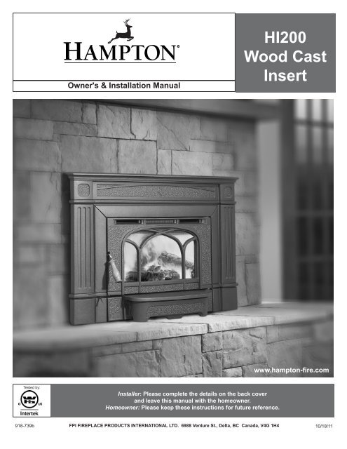
Owner's & Installation Manual<br />
<strong>HI200</strong><br />
<strong>Wood</strong> <strong>Cast</strong><br />
<strong>Insert</strong><br />
www.hampton-fire.com<br />
Tested by:<br />
Installer: Please complete the details on the back cover<br />
and leave this manual with the homeowner.<br />
Homeowner: Please keep these instructions for future reference.<br />
918-739b<br />
FPI FIREPLACE PRODUCTS INTERNATIONAL LTD. 6988 Venture St., Delta, BC Canada, V4G 1H4<br />
10/18/11
Thank-you for purchasing a<br />
HAMPTON FIREPLACE PRODUCT.<br />
The pride of workmanship that goes into each of our products will give you years of trouble-free enjoyment.<br />
Should you have any questions about your product that are not covered in this manual, please<br />
contact the HAMPTON DEALER in your area.<br />
Keep those HAMPTON FIRES burning.<br />
SAFETY NOTE: If this <strong>Insert</strong> is not properly installed, a house fire may result. For your safety, follow the<br />
installation instructions, contact local building or fire officials about restrictions and<br />
installation inspection requirements in your area.<br />
The authority having jurisdiction (such as municipal building department, fire department, fire<br />
prevention bureau, etc.) should be consulted before installation to determine the need to obtain<br />
a permit.<br />
2<br />
<strong>HI200</strong> Hampton <strong>Wood</strong> <strong>Cast</strong> <strong>Insert</strong>
TABLE OF CONTENTS<br />
SAFETY LABEL<br />
Copy of Safety Label......................................................4<br />
DIMENSIONS<br />
Unit Dimensions.............................................................5<br />
Standard Flue Adaptor...................................................5<br />
INSTALLATION<br />
Before Installing Your <strong>Insert</strong>...........................................7<br />
Chimney Specifications..................................................7<br />
<strong>Fireplace</strong> Specifications.................................................7<br />
Masonry And Factory Built <strong>Fireplace</strong> Clearances .........8<br />
How To Determine Floor Protection Materials................8<br />
Installing Your <strong>Insert</strong>.......................................................9<br />
Installation Into a Factory Built <strong>Fireplace</strong>..................... 11<br />
Installation Into a Masonry <strong>Fireplace</strong>........................... 11<br />
Fan & <strong>Cast</strong> Faceplate Installation................................12<br />
Brick Flue Baffle & Secondary Air Tube Installation.....14<br />
Firebrick Assembly.......................................................14<br />
Draft Control.................................................................14<br />
First Fire.......................................................................15<br />
Fan Operation..............................................................15<br />
MAINTENANCE<br />
Door Gasket.................................................................17<br />
Glass Cleaning.............................................................17<br />
Door Removal..............................................................17<br />
Glass Replacement......................................................17<br />
Handle Replacement...................................................18<br />
Latch Adjustment.........................................................18<br />
Annual Maintenance....................................................20<br />
PARTS LIST<br />
Main Assembly.............................................................21<br />
<strong>Cast</strong> Faceplate.............................................................22<br />
Firebrick.......................................................................22<br />
WARRANTY<br />
Warranty.......................................................................23<br />
OPERATING INSTRUCTIONS<br />
First Fire.......................................................................16<br />
Fan Operation..............................................................16<br />
Ash Disposal................................................................16<br />
Safety Guidelines.........................................................16<br />
Creosote......................................................................16<br />
http://oee.nrcan.gc.ca/residential/personal/retrofit-homes/retrofit-qualify-grant.cfm<br />
<strong>HI200</strong> Hampton <strong>Wood</strong> <strong>Cast</strong> <strong>Insert</strong><br />
3
339<br />
4<br />
SAFETY LABEL<br />
This is a copy of the label that accompanies each<br />
<strong>HI200</strong> <strong>Wood</strong> <strong>Insert</strong>. We have printed a copy of<br />
the contents here for your review.<br />
NOTE: Hampton units are constantly being<br />
improved. Check the label on the unit and if<br />
there is a difference, the label on the unit is<br />
the correct one.<br />
COMPONEN<br />
OFFSET AD<br />
OPTIONAL C<br />
DO NOT REM<br />
FIRE. BUILD<br />
WITH CERA<br />
MAY OCCUR<br />
CAUTION<br />
DO NOT REMOVE THIS LABEL<br />
339<br />
LISTED FACTORY BUILT FIREPLACE INSERT<br />
CERTIFIED FOR USE IN CANADA AND U.S.A.<br />
MODEL: <strong>HI200</strong><br />
TESTED TO:<br />
ULC S628-M93 / UL 1482-1998 / ULC S627-00 / UL 737-2000 REPORT NO. 632-3198 (SEPT.1993)<br />
INSTALL AND USE ONLY IN ACCORDANCE WITH THE MANUFACTURER'S INSTALLATION AND OPERATING INSTRUCTIONS. INSTALL AND USE ONLY<br />
IN MASONRY FIREPLACE OR FACTORY BUILT FIREPLACE.<br />
CONTACT LOCAL BUILDING OR FIRE OFFICIALS ABOUT RESTRICTIONS AND INSTALLATION INSPECTION IN YOUR AREA.<br />
UNITED STA<br />
AGENCY CE<br />
PARTICULA<br />
MINIMUM CLEARANCES TO COMBUSTIBLE MATERIALS (MEASURED FROM INSERT BODY)<br />
DATE O<br />
MANUFACT<br />
HOT WHILE IN OPERATION<br />
DO NOT TOUCH. KEEP CHILDREN,<br />
CLOTHING AND FURNITURE AWAY.<br />
CONTACT MAY CAUSE SKIN BURNS.<br />
READ ABOVE INSTRUCTIONS.<br />
INSTALL ONLY ON A NON-COMBUSTIBLE HEARTH RAISED (F) 1.5IN / 38MM<br />
ABOVE AN ADJACENT COMBUSTIBLE FLOOR. COMBUSTIBLE FLOOR MUST<br />
BE PROTECTED BY NON-COMBUSTIBLE MATERIAL EXTENDING<br />
(E) 16 IN / 405MM (US), 18 IN / 457MM (CAN) TO FRONT AND (G) 8 IN / 205MM<br />
TO SIDES FROM FUEL DOOR.<br />
ADJACENT SIDEWALL A) 15in / 380mm<br />
MANTLE B) 20in / 510mm<br />
TOP FACING C 14in / 355 mm<br />
SIDE FACING D) 7.375in / 185mm<br />
918-740<br />
THIS LABEL COMPONENTS REQUIRED FOR INSTALLATION: 5.5" (140mm) or 6" (152MM) STAINLESS STEEL LINER. STANDARD ADAPTOR (171-932) OR<br />
OFFSET ADAPTOR (171-936), FAN (210-911 or 210-915), ELECTRICAL RATING: VOLTS 115, 60 HZ, 0.6 AMPS<br />
OPTIONAL COMPONENT: SCREEN DOOR (846-101)<br />
DO NOT REMOVE BRICKS OR MORTAR IN MASONRY FIREPLACE. FOR USE WITH SOLID WOOD FUEL ONLY. DO NOT USE GRATE OR ELEVATE<br />
FIRE. BUILD WOOD FIRE DIRECTLY ON HEARTH. OPERATE WITH FEED DOOR CLOSED, OPEN TO FEED FIRE ONLY. REPLACE GLASS ONLY<br />
WITH CERAMIC GLASS (5MM). INSPECT AND CLEAN CHIMNEY FREQUENTLY. UNDER CERTAIN CONDITIONS OF USE CREOSOTE BUILDUP<br />
L AND USE ONLY<br />
MAY OCCUR RAPIDLY. DO NOT OVERFIRE, IF INSERT GLOWS YOU ARE OVER-FIRING.<br />
CAUTION<br />
Part #: 918-740<br />
Colour: Black on grey, except for selected items wh<br />
MADE IN CANADA<br />
Size: 15.75" W x 2" H (File at 100%)<br />
MANUFACTURED BY:<br />
FPI FIREPLACE PRODUCTS INTERNATIONAL LTD.<br />
6988 VENTURE ST.<br />
DELTA, BC V4G 1H4<br />
UNITED STATES ENVIRONMENTAL PROTECTION<br />
AGENCY CERTIFIED TO COMPLY WITH JULY 1990,<br />
PARTICULATE EMISSION STANDARDS.<br />
(Duplicate<br />
Serial #)<br />
JAN FEB MAR APR MAY JUN JUL AUG SEPT OCT NOV DEC<br />
2011 2012 2013<br />
DATE OF<br />
MANUFACTURE<br />
HOT WHILE IN OPERATION<br />
DO NOT TOUCH. KEEP CHILDREN,<br />
CLOTHING AND FURNITURE AWAY.<br />
CONTACT MAY CAUSE SKIN BURNS.<br />
READ ABOVE INSTRUCTIONS.<br />
(F) 1.5IN / 38MM<br />
LE FLOOR MUST<br />
ING<br />
(G) 8 IN / 205MM<br />
Mar. 13/08: Approved by ITS.<br />
Mar. 2/10: updated manufacture dates/ITS logo<br />
Apr. 4/11: updated manufacture dates/add 5.5" liner<br />
<strong>HI200</strong> Hampton <strong>Wood</strong> <strong>Cast</strong> <strong>Insert</strong><br />
: 918-740
DIMENSIONS<br />
UNIT DIMENSIONS WITH<br />
STANDARD FLUE ADAPTOR<br />
25”<br />
21-1/4”<br />
15-1/16”<br />
9-5/8”<br />
6-3/8”<br />
39-13/16” 2-7/8”<br />
27-1/4”<br />
19”<br />
to top of Door<br />
19-9/16”<br />
38-5/16”<br />
6" (152mm) Diameter<br />
24”<br />
STANDARD FLUE ADAPTOR (171-932)<br />
Door Width<br />
4-9/16”<br />
NOTE:<br />
Before assembling your <strong>Insert</strong>,<br />
use these dimensions to ensure<br />
appropriate clearances<br />
will be met (refer to Masonry<br />
and Factory Built <strong>Fireplace</strong><br />
Clearances section).<br />
<strong>HI200</strong> Hampton <strong>Wood</strong> <strong>Cast</strong> <strong>Insert</strong><br />
5
DIMENSIONS<br />
UNIT DIMENSIONS WITH<br />
OFFSET FLUE ADAPTOR<br />
25”<br />
21-1/4”<br />
17-11/16”<br />
15-1/16”<br />
14-1/8”<br />
6-3/8”<br />
39-13/16” 2-7/8”<br />
27-1/4”<br />
19-9/16”<br />
38-5/16”<br />
6" (152mm) Diameter<br />
OFFSET FLUE ADAPTOR (171-936)<br />
14-1/8” from flue centerline to rear of faceplate<br />
16-15/16” (430mm)<br />
4-9/16”<br />
NOTE:<br />
Before assembling your <strong>Insert</strong>,<br />
use these dimensions to ensure<br />
appropriate clearances<br />
will be met (refer to Masonry<br />
and Factory Built <strong>Fireplace</strong><br />
Clearances section).<br />
6<br />
<strong>HI200</strong> Hampton <strong>Wood</strong> <strong>Cast</strong> <strong>Insert</strong>
INSTALLATION<br />
Hampton <strong>Insert</strong>s are constructed with the highest<br />
quality materials and assembled under strict<br />
quality control procedures that ensure years of<br />
trouble free and reliable performance.<br />
It is important that you read this manual thoroughly<br />
and fully understand the installation and<br />
operating procedures. Failure to follow instructions<br />
may result in property damage, bodily injury<br />
or even death. The more you understand the way<br />
your Hampton <strong>Insert</strong> operates, the more enjoyment<br />
you will experience from knowing that your<br />
unit is operating at peak performance.<br />
BEFORE INSTALLING<br />
YOUR INSERT<br />
1) Read all instructions before installing and<br />
using your fireplace insert. Install and use<br />
only in accordance with manufacturer’s<br />
installation and operating instructions.<br />
2) Check your local building codes - Building<br />
Inspection Department. You may<br />
require a permit before installing your<br />
insert. Be aware that local codes and<br />
regulations may override some items in<br />
the manual.<br />
WARNING: Careless installation is the<br />
major cause of safety hazard. Check all<br />
local building and safety codes before<br />
installation of unit.<br />
3) Notify your home insurance company that<br />
you plan to install a fireplace insert.<br />
4) Your fireplace insert is heavy and requires<br />
two or more people to move it safely. The<br />
insert and surrounding structure can be<br />
badly damaged by mishandling.<br />
5) If your existing fireplace damper control<br />
will become inaccessible once you have<br />
installed your Hampton <strong>Insert</strong>, you should<br />
either remove or secure it in the open position.<br />
6) Inspect your fireplace and chimney prior<br />
to installing your insert to determine that it<br />
is free from cracks, loose mortar or other<br />
signs of damage. If repairs are required,<br />
they should be completed before installing<br />
your insert. Do not remove bricks or mortar<br />
from your masonry fireplace.<br />
7) Do not connect the insert to a chimney<br />
flue servicing another appliance or an air<br />
distribution duct.<br />
CHIMNEY<br />
SPECIFICATIONS<br />
Before installing, check and clean your chimney<br />
system thoroughly. If in doubt about its condition,<br />
seek professional advice. Your Hampton<br />
<strong>Insert</strong> is designed for installation into a masonry<br />
fireplace that is constructed in accordance with<br />
the requirements of "The Standard for Chimneys,<br />
<strong>Fireplace</strong>s, Vents, and Solid Fuel Burning Appliance",<br />
N.F.P.A. 211, the National Building<br />
Code of Canada, or the applicable local code<br />
requirements.<br />
The appliance, when installed, must be electrically<br />
grounded in accordance with local codes or,<br />
in the absence of local codes, with the National<br />
Electrical Code, ANSI/NFPA 70, or the Canadian<br />
Electrical code, CSA C22.1.<br />
Hampton <strong>Insert</strong>s are designed to use either a<br />
5.5" (140mm) or 6" (152mm) flue.<br />
This insert must be connected to a code-approved<br />
masonry chimney or listed factory-built<br />
fireplace chimney with a direct flue connector<br />
into the first chimney liner section. The chimney<br />
size should not be less than or more than three<br />
times greater than the cross-sectional area of<br />
the flue collar.<br />
Requirements for Installing<br />
Solid-fuel <strong>Insert</strong>s in Factory-built<br />
<strong>Fireplace</strong>s.<br />
1) The insert must be tested and meet the<br />
requirements of UL 1482 (U.S.) and or ULC<br />
S628 (Canada) when tested in a masonry<br />
fireplace built per ULC S628.<br />
2) The factory-built fireplace must be listed per<br />
UL 127 or ULC S610.<br />
3) Clearances obtained from the masonry fireplace<br />
tests are also relevant for installation<br />
in factory-built fireplaces.<br />
4) Installation must include a full height listed<br />
chimney liner type HT requirements (2100<br />
degree F.) per UL 1777 (U.S.) or ULC<br />
S635 (Canada). The liner must be securely<br />
attached to the insert flue collar and the<br />
chimney top.<br />
5) Means must be provided to prevent room<br />
air passage to the chimney cavity of the<br />
fireplace. This may be accomplished by<br />
sealing the damper area around the chimney<br />
liner, or sealing the fireplace front.<br />
6) Alteration of the fireplace in any manner is<br />
not permitted with the following exceptions;<br />
a. external trim pieces which do not affect<br />
the operation of the fireplace may be<br />
removed providing they can be stored on<br />
or within the fireplace for re-assembly if<br />
the insert is removed.<br />
b. the chimney damper may be removed to<br />
install the chimney liner.<br />
7) Circulating air chambers (i.e. in a steel fireplace<br />
liner or metal heat circulator) shall not<br />
be blocked.<br />
8) Means must be provided for removal of the<br />
insert to clean the chimney flue.<br />
9) <strong>Insert</strong>s that project in front of the fireplace<br />
must be supplied with appropriate supporting<br />
means.<br />
10) Installer must mechanically attach the supplied<br />
label to the inside of the firebox of the<br />
fireplace into which the insert is installed.<br />
"WARNING: This fireplace has been converted<br />
for use with a wood insert only and cannot be<br />
used for burning wood or solid fuels unless<br />
all original parts have been replaced, and the<br />
fireplace re-approved by the authority having<br />
jurisdiction."<br />
FIREPLACE<br />
SPECIFICATIONS<br />
Your fireplace opening requires the following<br />
minimum sizes:<br />
Height:<br />
Width:<br />
Depth:<br />
(w/ standard flue adaptor)<br />
(w/ offset flue adaptor)<br />
Faceplate Dimensions:<br />
Height<br />
Width<br />
19-5/8" (499mm)<br />
25" (635mm)<br />
15-1/16" (383mm)<br />
17-11/16" (449mm)<br />
27-1/4" (692mm)<br />
38-5/16" (973mm)<br />
Emissions from burning wood or gas could<br />
contain chemicals known to the State of California<br />
to cause cancer, birth defects or other<br />
reproductive harm.<br />
<strong>HI200</strong> Hampton <strong>Wood</strong> <strong>Cast</strong> <strong>Insert</strong><br />
7
INSTALLATION<br />
MASONRY AND FACTORY BUILT FIREPLACE CLEARANCES<br />
The minimum required clearances to combustible materials when installed into a masonry or factory built fireplace are listed below.<br />
Adjacent Mantle** Top Side Minimum Minimum Minimum<br />
Side Wall (to Top) Facing Facing Hearth Hearth Hearth Side<br />
(to Side) (to Top) (to Side) Extension Thickness* Extension<br />
A B C D E F G<br />
15" (381mm) 20" (508mm) 14" (356mm) 7-3/8"(187mm) 16" (406mm) [US] 1-1/2" (38mm) 6" (152mm) [US]<br />
18" (457mm) [CAN] 8" (203mm) [CAN]<br />
Side and Top facing is a maximum of 1.5" thick.<br />
Floor protection must non-combustible, insulative<br />
material with an R value of 1.1 or greater.<br />
* If the hearth extension is flush with the floor (F)<br />
it must extend 19.5" in front of the body face<br />
(E).<br />
B<br />
C<br />
Note: Hearth Extension Width (G) is measured<br />
from edge of fuel door to side of<br />
hearth.<br />
** A non-combustible mantel may be installed<br />
at a lower height if the framing is made of<br />
metal studs covered with a non-combustible<br />
board.<br />
A<br />
D<br />
E<br />
Thermal floor protection is not required if the unit is<br />
raised 3.5" minimum (measured from the bottom of<br />
the stove). However, standard ember floor protection<br />
is required. It will need to be a non-combustible material<br />
that covers 16" (406 mm) in the US and 18" (450<br />
mm) in Canada to the front of the unit and 8" (200<br />
mm) to the sides.<br />
If the unit is not raised, thermal floor protection required<br />
is 18" (450 mm) in the US and Canada.<br />
F<br />
Clearance diagram for installations<br />
Floor Protection<br />
Please check to ensure that your floor protection and hearth will meet the standards for clearance<br />
to combustibles. Your hearth extension must be made from a non-combustible material.<br />
G<br />
HOW TO DETERMINE IF ALTERNATE<br />
FLOOR PROTECTION MATERIALS ARE ACCEPTABLE<br />
The specified floor protector should be 3/8"<br />
(18mm) thick material with a K - factor of<br />
0.84.<br />
The proposed alternative is 4" (100mm) brick<br />
with a C-factor of 1.25 over 1/8" (3mm) mineral<br />
board with a K-factor of 0.29.<br />
Step (a):<br />
Use formula above to convert specification<br />
to R-value.<br />
R = 1/k x T = 1/0.84 x .75 = 0.893.<br />
Step (b):<br />
Calculate R of proposed system.<br />
4" brick of C = 1.25, therefore<br />
Rbrick = 1/C = 1/1.25 = 0.80<br />
1/8" mineral board of k = 0.29, therefore<br />
Rmin.bd. = 1/0.29 x 0.125 = 0.431<br />
Total R = Rbrick + Rmineral board =<br />
0.8 + 0.431 = 1.231.<br />
Step (c):<br />
Compare proposed system R of 1.231 to<br />
specified R of 0.893. Since proposed system<br />
R is greater than required, the system is<br />
acceptable.<br />
DEFINITIONS<br />
Thermal Conductance:<br />
C = Btu = W<br />
(hr)(ft 2 )( o F) (m 2) )(K)<br />
Thermal Conductivity:<br />
k = (Btu)(inch) = W = Btu<br />
(hr)(ft 3 )( o F) (m)(K) (hr)(ft)( o F)<br />
Thermal Resistance:<br />
R = (ft 2 )(hr)( o F) = (m 2 )(K)<br />
Btu W<br />
8<br />
<strong>HI200</strong> Hampton <strong>Wood</strong> <strong>Cast</strong> <strong>Insert</strong>
INSTALLATION<br />
INSTALLING YOUR INSERT<br />
STOP! PLEASE READ CAREFULLY.<br />
CAST COMPONENTS ARE VERY FRAGILE.<br />
USE EXTREME CARE WHEN HANDLING.<br />
3) Lift the unit up onto the Hearth and slide into the fireplace opening.<br />
Be sure to leave the unit out at least 3 to 4 inches in order to make<br />
the necessary flue connections and to install the fan and faceplate.<br />
Be sure to protect your hearth extension during the installation,<br />
ie. with a heavy blanket.<br />
Your insert is very heavy and will require two or three people to<br />
move it into position.<br />
1) Remove the Door to make the insert easier to handle.<br />
To remove the Door, open fully and release the push pin at the top<br />
of the door and lift out from the bottom.<br />
NOTE: You will be required to purchase either the standard or offset<br />
6" diameter (152mm) flue adaptor that is best suited for the specific<br />
installation.<br />
List of Tools needed;<br />
- Pull Rod (included with insert)<br />
- 1/2” socket / ratchet<br />
- 3/8 open face wrench<br />
4) Install flex liner into existing chimney as per liner manufacturer’s<br />
specifications. See diagram 1.<br />
Push Pin<br />
5) Install the required flue adaptor onto the end of the flex liner. Secure<br />
the adaptor using 3 screws - 1 on the front, left and right side as<br />
shown in diagram 2.<br />
Alignment of the flue adaptor can be critical during the install, it is<br />
recommended that the flex liner be left as compressed as possible.<br />
Before inserting the unit the adaptor should hang, when level, slightly<br />
above the required height.<br />
Diagram 1<br />
Flex Liner<br />
2) NOTE: For Masonry installation make sure that the firebox is level<br />
with the hearth using non-combustible materials and no more than<br />
1/2 to 1 inch of the leveling bolt.<br />
Diagram 2<br />
Flue Adaptor<br />
Secure adaptor using 3 screws - 1 in the front<br />
and 1 each on the left and right side.<br />
<strong>HI200</strong> Hampton <strong>Wood</strong> <strong>Cast</strong> <strong>Insert</strong><br />
9
INSTALLATION<br />
6) Install the unit by first setting the rear of the unit into the fireplace. See<br />
diagram 3. Ensure that the unit is centered in the existing fireplace<br />
and lined up with the flue adaptor.<br />
10) Ensure that the unit is still level.<br />
11) To complete the installation and to ensure a secure fit and connection<br />
of the flue adaptor to the insert, it is essential that the two bolts,<br />
flat washers and lock washers (supplied with packaged manual) be<br />
installed and tightened using a 1/2" socket as shown in diagram 6.<br />
This prevents the possibility of creosote drip and exhaust gas leakage.<br />
Diagram 3<br />
7) Slide the unit back until the flue adaptor is slightly engaged.<br />
8) At this point it is recommended to level the unit and ensure that the<br />
leveling bolts rest on the surface of the fireplace. This will keep the<br />
adaptor from binding as the unit is slid into position.<br />
9) <strong>Insert</strong> the provided pull rod through the hole in the top center of<br />
the unit. Secure the threaded end into the flue adaptor as shown in<br />
diagram 4. While sliding the unit into place pull on the rod to ensure<br />
that the flue adaptor is properly engaged. See diagram 5.<br />
Diagram 6<br />
12) Remove the pull rod from the top center of the fireplace. See<br />
diagram 7.<br />
Diagram 4<br />
Pull Rod<br />
Pull Rod<br />
Diagram 7<br />
NOTE: The pull rod should not be thrown away. It should be kept if<br />
the stove is ever needed to be removed from the fireplace.<br />
Diagram 5: Pull Rod In Place<br />
10<br />
<strong>HI200</strong> Hampton <strong>Wood</strong> <strong>Cast</strong> <strong>Insert</strong>
INSTALLATION<br />
INSTALLATION INTO A<br />
MASONRY FIREPLACE<br />
When referencing installation or connection<br />
to masonry fireplaces or chimneys, the<br />
masonry construction must or shall be code<br />
complying.<br />
The insert must be installed as per the requirements<br />
of your local inspection authority. Three<br />
methods of flue connection are acceptable in<br />
most areas, these include:<br />
1) Positive flue connection, where a large<br />
blocking plate and a short connector pipe<br />
is used.<br />
2) Direct flue connection, where a smaller<br />
blocking plate and a connector pipe to the<br />
first flue liner tile is used.<br />
3) Full flue liner, where a stainless steel rigid<br />
or flexible liner pipe is routed from the insert<br />
outlet collar to the top of the chimney.<br />
Hampton highly recommends the use of a full<br />
liner as the safest installation and provides the<br />
most optimum performance. Your retailer should<br />
be able to help you decide which system would<br />
be the best for your application.<br />
In Canada this fireplace insert must be<br />
installed with a continuous chimney liner<br />
of 5.5" or 6" diameter extending from the<br />
fireplace insert to the top of the chimney.<br />
The chimney liner must conform to the<br />
Class 3 requirements of CAN/ULC-S635<br />
or CAN/ULC-S640, Standard for Lining<br />
Systems for New Masonry Chimneys.<br />
Note: A clean-out door is sometimes<br />
required, by your inspector, to be<br />
installed when either the Positive flue<br />
connection or Direct flue connection<br />
method is used.<br />
The use of one of the connection methods listed<br />
on this page not only increases the safety of your<br />
insert by directing the hot gases up the flue, but<br />
will also help increase the unit's efficiency and<br />
decrease creosote deposits in the chimney.<br />
When a connected flue or liner is in use, the<br />
insert is able to “breathe” better by allowing a<br />
greater draft to be created. The greater draft can<br />
decrease problems such as, difficult start-ups,<br />
smoking out the door, and dirty glass.<br />
INSTALLATION INTO A<br />
FACTORY BUILT<br />
FIREPLACE<br />
1) When installed in a factory built fireplace, a<br />
full stainless steel rigid or flexible flue liner<br />
is mandatory, for both safety and performance<br />
purposes. When a flue or liner is in<br />
use, the insert is able to breathe better by<br />
allowing a greater draft to be created. The<br />
greater draft can decrease problems such<br />
as, difficult start-ups, smoking out the door,<br />
and dirty glass.<br />
4) If the floor of your fireplace is below the<br />
level of the fireplace opening, adjust the<br />
insert's levelling bolts to accommodate the<br />
difference. When additional shimming is<br />
required, use non-combustible masonry or<br />
steel shims.<br />
5) Measure approximately the alignment of the<br />
flue liner with the position of the smoke outlet<br />
hole on the insert to check for possible offset.<br />
If an offset is required, use the appropriate<br />
offset adaptor in your installation.<br />
6) Once the above items have been checked,<br />
slide your insert into position after first positioning<br />
and securing the flue liner to the<br />
offset adaptor.<br />
Attach the rod to the adaptor and slide the<br />
adaptor onto the unit as the unit is slid into<br />
position. Ensure a positive connection.<br />
Secure the adaptor to the unit by using 2<br />
bolts, flat washers, lock washers and one<br />
screw in the front.<br />
Re-install raincap at completion of installation.<br />
1) Positive Flue<br />
Connection<br />
with Cleanout<br />
2) Direct Flue<br />
Connection<br />
with Cleanout<br />
2) In order to position the flue liner, the existing<br />
rain cap must be removed from your<br />
chimney system. In most cases the flue<br />
damper should also be removed to allow<br />
passage of the liner.<br />
3) In most cases opening the existing spark<br />
screens fully should give enough room for<br />
the insert installation. If it does not, remove<br />
and store.<br />
Installer: Please record unit serial number here before installing blower.<br />
3a) Full Flue Liner<br />
(No Cleanout<br />
Required)<br />
Serial No.______________________________<br />
<strong>HI200</strong> Hampton <strong>Wood</strong> <strong>Cast</strong> <strong>Insert</strong><br />
11
INSTALLATION<br />
<strong>HI200</strong><br />
FAN<br />
FAN &<br />
CAST<br />
CAST<br />
FACEPLATE<br />
FACEPLATE<br />
INSTALLATION<br />
INSTALLATION<br />
Stop! Read Carefully.<br />
Enamel & <strong>Cast</strong> components are very fragile. Use extreme care when handling.<br />
Note: The liner and flue adaptor should be installed prior to<br />
reading these instructions.<br />
1) With door already removed - place fan in front of unit as shown below,<br />
Loosen 2 fl ange bolts - adjust fl ange to rest on fan assembly, once<br />
height has been determined .<br />
Leave 2" between fan and unit, tighten 2 fl ange bolts using 7/16"<br />
open end wrench.<br />
Fan assembly can now be secured to the unit using 2 bolts on both<br />
left and right side - see Diagrams 1 & 2.<br />
2) Slide the unit into position leaving partially out to allow for installation<br />
of the left and right side surrounds.<br />
3) Install the left and right side surround to the mounting brackets on<br />
the unit using 2 bolts per side. See Diagram 3.<br />
Gasket<br />
Mounting Bracket<br />
Mounting Bracket<br />
Gasket<br />
Diagram 3<br />
4) Place a strip of gasket on top of the left and right side surround on<br />
the front lip of the side castings. See Diagram 3.<br />
5) Carefully slide the top surround in place by aligning the mounting<br />
plates with the two retainers in the left and right side surrounds.<br />
See Diagram 4.<br />
Diagram 1<br />
Diagram 2: Back View of<br />
Fan Installation<br />
Note: If screws do not lineup, loosen the 2 screws per side as shown in<br />
Diagram 2 and adjust left side and right side facia. Tighten the 2 screws<br />
per side and install the fan on the unit.<br />
Diagram 4<br />
12<br />
918-745b 1<br />
<strong>HI200</strong> Hampton <strong>Wood</strong> 02/19/09 <strong>Cast</strong> <strong>Insert</strong>
<strong>HI200</strong><br />
INSTALLATION<br />
6) Place ashlip over fan by fi tting it onto the fl ange on the fi rebox.<br />
See Diagram 5 and 6.<br />
7) Install door and close with caution - adjustments may be<br />
necessary.<br />
Diagram 7<br />
Diagram 5<br />
8) Surround adjustments can be made up or down, loosen 4 bolts<br />
shown on face of unit (Diagram 7) and adjust.<br />
Surround can also be adjusted left or right, loosen 4 bolts shown in<br />
Diagram 3 - adjust surround left or right and retighten bolts.<br />
Check that gaps around door are even and door closes properly.<br />
9) Completely slide unit into place - after all adjustments have been<br />
made.<br />
DO NOT ROUTE THE FAN POWER CORD<br />
UNDER OR IN FRONT OF THE UNIT.<br />
Ashlip<br />
Do not turn the fan ON until your insert has reached<br />
operating temperature or at least 30 minutes after<br />
starting fire.<br />
Diagram 6<br />
13<br />
<strong>HI200</strong> Hampton <strong>Wood</strong> <strong>Cast</strong> <strong>Insert</strong><br />
918-745b 2<br />
02/19/09
INSTALLATION<br />
FIREBRICK ASSEMBLY<br />
Firebrick is included to extend the life of your<br />
insert and radiate heat more evenly. Check to<br />
see that all firebricks are in their correct positions<br />
and have not become misaligned during<br />
shipping.<br />
Side View<br />
3) Tilt the left baffle brick up on top of the side<br />
channel and it will leave enough room to<br />
position the right baffle brick in the same<br />
manner as Step 1) above. Then reposition<br />
the left baffle brick flat on the air tube.<br />
DRAFT CONTROL<br />
Before establishing your first fire, it is important<br />
that you fully understand the operation of draft<br />
control. The draft control rod is on the left side<br />
of the <strong>Insert</strong> and it controls the intensity of the<br />
fire by increasing or decreasing the amount<br />
of air allowed into the firebox. To increase the<br />
draft, slide the rod to the left and to decrease<br />
the draft, slide the rod to the right.<br />
BRICK FLUE BAFFLE &<br />
SECONDARY AIR TUBE<br />
INSTALLATION<br />
The flue baffle system located in the upper area<br />
of the firebox is removable to make cleaning<br />
your chimney system easier. The brick baffles<br />
must be installed prior to your first fire. Smoke<br />
spillage and draft problems may occur if the<br />
baffles are improperly positioned. Check the<br />
position of the brick baffles on a regular basis as<br />
they can be dislodged if too much fuel is forced<br />
into the firebox.<br />
1) If the two air tubes are installed continue<br />
on to Step 2), if not, follow the instructions<br />
below. Install the air tube into the holes in the<br />
side channels. The notch goes on the right<br />
hand side with the air holes facing toward<br />
the door. Slide the tube into the left hand<br />
side, as far as possible and then bring it back<br />
into the hole on the right hand side until it<br />
locks into position. If the tube will not slide<br />
in easily simply use a pair of vise grips or<br />
pliers and tap it into place with a hammer. A<br />
tighter fit will ensure the tube will not move<br />
when the unit is burning.<br />
2) Slide the left baffle brick over the front air<br />
tube and then slide it back over the rear air<br />
tube.<br />
Front View<br />
4) Important: push both baffle bricks so<br />
they are tight against the side walls and<br />
to the back.<br />
Front View<br />
Note: When getting the chimney cleaned,<br />
remove the baffle bricks for access<br />
to the flue, then replace them when<br />
cleaning is completed.<br />
Slide Left to<br />
Increase Draft<br />
Slide Right to<br />
Decrease Draft<br />
As well as a primary and glass wash air system,<br />
the unit has a full secondary draft system that<br />
allows air to the induction ports at the top of the<br />
firebox, just below the flue baffle.<br />
WARNING: To build a fire in ignorance or to<br />
disregard the informa tion contained in this<br />
section can cause serious permanent damage<br />
to the unit and void your warranty.<br />
14<br />
<strong>HI200</strong> Hampton <strong>Wood</strong> <strong>Cast</strong> <strong>Insert</strong>
OPERATING INSTRUCTIONS<br />
INSTALLATION<br />
FIRST FIRE<br />
When your installation is completed and inspected,<br />
you are ready for your first fire.<br />
1) Open draft control fully.<br />
2) Open firebox door and build a small fire using<br />
paper and dry kindling, wait a few minutes<br />
for a good updraft in the flue to establish the<br />
fire. Leaving the door slightly open will help<br />
your fire start more rapidly.<br />
CAUTION: Never leave unit unattended<br />
if door is left open. This procedure is for<br />
fire start-up only, as unit may over-heat<br />
if door is left open for too long.<br />
3) With the draft still in the fully open position,<br />
add two or three seasoned logs to your fire.<br />
Form a trench in the ash bed to allow air to<br />
reach the rear of the firebox prior to closing<br />
the door.<br />
4) After about 15 to 20 minutes, when your<br />
wood has begun to burn strongly, adjust<br />
your draft control down to keep the fire at a<br />
moderate level.<br />
WARNING: Never build a roaring fire in<br />
a cold stove. Always warm your stove<br />
up slowly!<br />
5) Once a bed of coals has been established,<br />
you may adjust the draft control to a low<br />
setting to operate the unit in its most efficient<br />
mode.<br />
6) During the first couple of hours, keep the<br />
combustion rate at a moderate level and<br />
avoid a large fire until the paint is cured.<br />
Only then can you operate the insert at its<br />
maximum setting, and only after the metal<br />
has been warmed.<br />
7) For the first few hours, the insert will give<br />
off an odour from the paint. This is to be<br />
expected as the high temperature paint<br />
becomes seasoned. Windows and/or doors<br />
should be left open to provide adequate<br />
ventilation while this temporary condition<br />
exists. Burning the insert at a very high<br />
temperature the first few times may damage<br />
the paint. Burn fires at a moderate level the<br />
first few days.<br />
8) Do not place anything on the insert top<br />
during the curing process. This may result<br />
in damage to your paint finish.<br />
9) During the first few hours it may be more difficult<br />
to start the fire. As you dry out your fire<br />
brick and your masonry flue (if applicable),<br />
your draft will increase.<br />
10) For those units installed at higher elevations<br />
or into sub-standard masonry fireplaces,<br />
drafting problems may occur. Consult an<br />
experienced dealer or mason on methods<br />
of increasing your draft.<br />
11) Some cracking and popping noises may be<br />
experienced during the heating up process.<br />
These noises will be minimal when your unit<br />
reaches temperature.<br />
12) Before opening your door to reload, open<br />
draft fully for approximately 10 to 15 seconds<br />
until fire has been re-established. This will<br />
minimize any smoking.<br />
13) All fuel burning appliances consume oxygen<br />
during operation. It is important that you<br />
supply a source of fresh air to your unit<br />
while burning. A slightly opened window is<br />
sufficient for this purpose.<br />
CAUTION: If the body of your unit starts<br />
to glow you are overfiring. Stop loading<br />
fuel immediately and close the draft<br />
control until the glow has completely<br />
subsided.<br />
14) Green or wet wood is not recommended for<br />
your unit. If you must add wet or green fuel,<br />
open the draft control fully until all moisture<br />
has been dispersed by the intense fire.<br />
Once all moisture has been removed, the<br />
draft control may be adjusted to maintain<br />
the fire.<br />
15) If you have been burning your insert on a<br />
low draft, use caution when opening the<br />
door. After opening the damper, open the<br />
door a crack, and allow the fire to adjust<br />
before fully opening the door.<br />
16) The controls of your unit should not be<br />
altered to increase firing for any reason.<br />
FAN OPERATION<br />
The fan is to be operated only with the draft<br />
control rod pulled out at least 1/2" from the<br />
fully closed position. The fan is not to be<br />
operated when the draft control rod is in the<br />
closed position (pushed in). The fully closed<br />
position is the low burn setting.<br />
The fan must not be turned on until a fire has<br />
been burning for at least 30 minutes. Also note<br />
it is recommended that the fan be turned off<br />
before each fuel loading and again wait for 30<br />
minutes before the fan is turned on again. This<br />
is too allow the stove to reach it's optimum<br />
temperature.<br />
To operate fan automatically, push switch on the<br />
right side of fan housing to "Auto" and second<br />
switch, on the left to either "High" or "Low" for<br />
fan speed. The automatic temperature sensor<br />
will engage the blower when the unit is at<br />
temperature and will shut off the blower once<br />
the fire has gone out and the unit has cooled to<br />
below a useful heat output range.<br />
Auto|Man Switch<br />
Fan Control Location<br />
High|Low|Off Switch<br />
To manually operate the fan system, push the<br />
switch on the left to "Man" and switch on the<br />
right to either "high" or "Low". This will bypass<br />
the sensing device and allow full control of the<br />
fan. Switching from "Auto" to "Manual" or "High"<br />
to "Low" may be done at any time.<br />
Fan Wiring Diagram<br />
<strong>HI200</strong> Hampton <strong>Wood</strong> <strong>Cast</strong> <strong>Insert</strong><br />
15
OPERATING INSTRUCTIONS<br />
ASH DISPOSAL<br />
During constant use, ashes should be removed<br />
every few days. Please take care to prevent the<br />
build-up of ash around the start-up air housing<br />
located inside the firebox, under the loading<br />
door lip.<br />
DO NOT ALLOW ASHES TO BUILD UP TO<br />
THE LOADING DOORS.<br />
Only remove ashes when the fire has died down.<br />
Even then, expect to find a few hot embers.<br />
Always leave 1 to 2 inches of ash in the bottom<br />
of the firebox. This helps in easier starting and<br />
a more uniform burn of your fire.<br />
Ashes should be placed in a metal container with<br />
a tight fitting lid. The closed container of ashes<br />
should be placed on a noncombustible floor or<br />
on the ground, well away from all combustible<br />
materials, pending final disposal. If the ashes<br />
are disposed of by burial in soil or otherwise<br />
locally dispersed, they should be retained in the<br />
closed container until all cinders have thoroughly<br />
cooled. Other waste should not be placed in<br />
the ash container.<br />
SOME SAFETY<br />
GUIDELINES<br />
1) Never use gasoline, gasoline type lantern fuels,<br />
kerosene, charcoal lighter fuel, or similar<br />
liquids or chemicals to start or ‘freshen up’ a<br />
fire in your insert. Keep all such liquids well<br />
away from the heater while it is in use.<br />
2) Never use alternate fuels such as charcoal<br />
that have the possibility of generating carbon<br />
monoxide.<br />
3) Keep the door closed during operation and<br />
maintain all seals in good condition.<br />
4) Do not burn large quantities of paper in your<br />
insert.<br />
5) Do not burn garbage or flammable fluids.<br />
6) If you have smoke detectors, prevent smoke<br />
spillage as this may set off a false alarm.<br />
7) Do not overfire your insert. If the insert or its<br />
flue baffle begin to glow, you are overfiring.<br />
Stop adding fuel and close the draft control.<br />
Overfiring can cause extensive damage to<br />
your stove including warpage and premature<br />
steel corrosion. Overfiring will void your<br />
warranty.<br />
8) Do not permit creosote or soot buildup in the<br />
chimney system. Check and clean chimney<br />
at regular intervals.<br />
9) Your Hampton <strong>Insert</strong> can be very hot. You<br />
may be seriously burned if you touch the<br />
insert while it is operating. Warn children of<br />
the burn hazard. Keep furniture and clothing<br />
away.<br />
10) The insert consumes air while operating,<br />
provide adequate ventilation with an air duct<br />
or open a window while the insert is in use.<br />
11) Do not use grates, irons or other methods<br />
for supporting fuel. Burn directly on the<br />
bricks.<br />
12) Open the draft control fully for 10 to 15<br />
seconds prior to slowly opening the door<br />
when refuelling the fire.<br />
13) Do not connect your unit to any air distribution<br />
duct.<br />
14) Your insert should burn dry, standard firewood<br />
only. The use of “mill ends” is discouraged<br />
as this fuel can easily overheat your<br />
insert. Evidence of excessive overheating<br />
will void your warranty. As well, a large portion<br />
of sawmill waste is chemically treated<br />
lumber, which is illegal to burn in many areas.<br />
Chemically treated fire logs also must not<br />
be burned in your insert.<br />
15) Do not store any fuel closer than 2 feet from<br />
your unit.<br />
16) Do not burn salt drift wood as it will corrode<br />
your unit and void the warranty.<br />
17) Do not strike or slam the glass door shut as<br />
this may cause the glass to break.<br />
18) Do not operate the unit if the glass is broken<br />
or missing. Do not operate the unit if the<br />
gasketing is worn out and not sealing the<br />
door or the glass.<br />
It is very important to carefully maintain your<br />
insert, including burning seasoned wood and<br />
maintaining a clean stove and chimney system.<br />
Have the chimney cleaned before the burning<br />
season and as necessary during the season, as<br />
creosote deposits may build up rapidly. Moving<br />
parts of your insert require no lubrication.<br />
CREOSOTE<br />
When wood is burned slowly, it produces tar and<br />
other organic vapors, which form creosote when<br />
combined with moisture. The creosote vapors<br />
condense in the relatively cool chimney flue of a<br />
slow-burning fire. As a result, creosote residue<br />
accumulates on the flue lining. When ignited,<br />
this creosote can make an extremely hot fire.<br />
Removal for Cleaning etc.<br />
Removal of your insert for cleaning purposes is<br />
usually not required if a proper installation has<br />
been done. In the event that removal is required,<br />
be sure not to damage any parts needed for<br />
re-installation. In most cases removal and<br />
replacement of the baffle system should allow<br />
full access for cleaning.<br />
WARNING: Things to remember in<br />
case of chimney fire:<br />
1) Close draft control<br />
2) Call the Fire Department<br />
Ways to Prevent and<br />
Keep Unit Free of Creosote<br />
1) Burn insert with draft control wide open for<br />
about 15 minutes every morning during<br />
burning season. This helps to prevent creosote<br />
deposits within the heating system.<br />
2) Burn insert with draft control wide open for<br />
about 10 - 15 minutes every time you add<br />
fresh wood. This allows the wood to achieve<br />
the charcoal stage faster and burns up any<br />
wood vapors which might otherwise be<br />
deposited within the system.<br />
3) Only burn seasoned wood! Avoid burning<br />
wet or green wood. Seasoned wood has<br />
been dried at least one year.<br />
4) A small hot fire is preferable to a large<br />
smouldering one that can deposit creosote<br />
within the system.<br />
5) Check the chimney at least twice a month<br />
during the burning season for creosote<br />
build-up.<br />
6) Have chimney system and unit cleaned by<br />
competent chimney sweeps twice a year<br />
during the first year of use and at least once<br />
a year thereafter or when needed.<br />
16<br />
<strong>HI200</strong> Hampton <strong>Wood</strong> <strong>Cast</strong> <strong>Insert</strong>
MAINTENANCE<br />
DOOR GASKET<br />
If the door gasket requires replacement, 7/8" diameter material must be<br />
used. A proper high temperature gasket adhesive is required. A gasket<br />
repair kit, Part # 846-570 is available from your local Hampton dealer.<br />
GLASS CLEANING<br />
Only clean your glass window when it is cool. Your local retailer can<br />
supply you with special glass cleaner if plain water and a soft cloth does<br />
not remove all deposits.<br />
DOOR REMOVAL<br />
When handling enamel parts, please handle with care as they can<br />
be damaged.<br />
1) Remove door from unit.<br />
GLASS<br />
REPLACEMENT<br />
2) To replace the glass remove the 4 screws highlighted in the diagram<br />
below.<br />
3) Lift off the glass retainer and carefully remove the glass.<br />
4) Place new glass in the door, make sure that the glass gasketing will<br />
properly seal your unit.<br />
5) Re-install the glass retainer. Ensure that it rests on the gasket and<br />
not the glass.<br />
6) Secure glass retainer using the 4 screws. Do not wrench down on<br />
the glass as this may cause the glass to break.<br />
7) Place door back on unit.<br />
1) Open door fully.<br />
2) Release the push pin at the top of the door and slide out while lifting<br />
up and out from the bottom.<br />
Please be careful when removing the Door and do not drop<br />
onto the Ashlip, it may chip.<br />
Push Pin<br />
Remove 4 screws.<br />
Avoid impact on glass doors such<br />
as striking or slamming shut.<br />
DOOR INSTALLATION NOTE<br />
After re-installing the door, carefully<br />
swing open and check the clearance<br />
to the Right Hand <strong>Cast</strong> Side. If tight or<br />
rubbing, loosen the 7/16 nuts and adjust<br />
the clearance and then re-tighten.<br />
<strong>HI200</strong> Hampton <strong>Wood</strong> <strong>Cast</strong> <strong>Insert</strong><br />
17
MAINTENANCE<br />
HANDLE<br />
REPLACEMENT<br />
1) Remove handle by undoing the hex head bolt using a 7/16" socket<br />
wrench.<br />
2) Fit new door handle over door latch and secure.<br />
Assemble handle by:<br />
a) Placing lock washer and split lock washer over hex head bolt.<br />
b) Place hex head bolt into handle.<br />
c) Place spacer over hex head bolt threads.<br />
d) Screw handle into door latch.<br />
LATCH ADJUSTMENT<br />
The door latch may require adjustment as the door gasket material compresses<br />
over time. Removal of spacers will allow the latch to be moved<br />
closer to the door frame, causing a tighter seal.<br />
1) Remove the Latch Assembly from the unit by undoing the 2 outer hex<br />
bolts.<br />
2) Remove the Latch from the Mounting Bracket by undoing the 2 inner<br />
hex bolts.<br />
3) Remove the necessary amount of spacers sitting on the Mounting<br />
Bracket. Ensure an equal amount of spacers are removed from both<br />
top and bottom.<br />
4) Re-secure the Latch to the Mounting Bracket using 2 inner hex<br />
bolts.<br />
5) Re-secure the Latch Assembly to the unit using the 2 outer hex<br />
bolts.<br />
18<br />
<strong>HI200</strong> Hampton <strong>Wood</strong> <strong>Cast</strong> <strong>Insert</strong>
MAINTENANCE<br />
LATCH ADJUSTMENT<br />
The door latch or door alignment may require adjustment as the door gasket material compresses after a few fires. Removal of spacers will allow<br />
the latch to be moved closer to the door frame, causing a tighter seal and the ability to raise or lower the latch assembly.<br />
1) Raise or lower the latch by undoing the inner 2 bolts. Adjust to<br />
desired location and retighten the 2 bolts, make sure the door catch<br />
closes freely and makes a good seal. Do a paper test to confirm seal.<br />
3) Remove necessary amount of spacers sitting on the Mounting<br />
Bracket.<br />
Ensure an equal amount of spacers are removed from both<br />
top and bottom.<br />
Mounting<br />
Bracket<br />
Spacers<br />
Latch<br />
Mounting<br />
Bracket<br />
2) For Door Gasket Seal, remove the Latch Assembly from the unit by<br />
undoing the outer 2 bolts.<br />
4) Re-secure Latch to Mounting Bracket using 2 bolts<br />
Latch Assembly re-assembled with<br />
spacers removed.<br />
Latch<br />
Assembly<br />
Latch Assembly<br />
removed from unit.<br />
5) Re-secure the Latch Assembly to the unit using 2 bolts.<br />
Confirm proper location of the door catch so that it closes tight,<br />
freely.<br />
<strong>HI200</strong> Hampton <strong>Wood</strong> <strong>Cast</strong> <strong>Insert</strong><br />
19
MAINTENANCE<br />
Completely clean out entire unit<br />
Inspect air tubes, baffles and bricks<br />
Adjust door catch / latch<br />
Inspect condition and seal of:<br />
Glass Gasket<br />
Door Gasket<br />
Paper Test<br />
Check and lubricate door hinge + latch<br />
Check glass for cracks<br />
Clean blower motor<br />
Inspect and clean chimney<br />
Annual Maintenance<br />
Annually<br />
Replace any damaged parts.<br />
If unable to obtain a tight seal on the door - replace door gasket seal.<br />
Readjust latch after new gasket installed.<br />
Perform paper test - replace gasket if required<br />
Test the seal on the loading door with a paper bill.<br />
Place a paper bill in the gasketed area of the door on a cold stove–close<br />
the door.<br />
Try to remove the paper by pulling.<br />
The paper should not pull out easily, if it does, try adjusting the door latch,<br />
if that doesn't solve the problem replace the door gasket.<br />
Use only high temperature anti seize lube. (ie. never seize)<br />
Replace if required.<br />
Disconnect power supply.<br />
Remove and clean blower.<br />
*DO NOT LUBRICATE*<br />
Annual professional chimney cleaning recommended.<br />
20<br />
<strong>HI200</strong> Hampton <strong>Wood</strong> <strong>Cast</strong> <strong>Insert</strong>
PARTS LIST<br />
MAIN ASSEMBLY<br />
Part #<br />
Description<br />
1) 948-163 Cane Bolt Latch<br />
2) 940-356/P Glass - Replacement<br />
3) 948-467 Hinge Pin Lower<br />
4) 936-238 Adhesive Tape Gasket<br />
5) 210-554 Glass Retainer Clips / Screws (set of 4)<br />
6) * Screws - 10-24 x 3/8"<br />
9) 210-550 Door Handle Assembly<br />
10) 210-561 Door Assembly Metallic Black (no glass)<br />
210-565 Door Assembly Timberline Brown (no glass)<br />
846-570 Med. Density Door Gasket Kit<br />
20) 210-911 Fan / Blower Assembly (Metallic Black)<br />
210-915 Fan / Blower Assembly (Timberline Brown)<br />
910-157/P Blower/Fan Motor<br />
910-684 Power Cord (120 Volts)<br />
910-142 Fan Thermodisc<br />
910-140 Fan Speed Switch - HI/OFF/LOW (3-way)<br />
910-138 Switch - Auto/Manual (2-way)<br />
21) * Front Fan Fascia<br />
22) * Right Side Fan Fascia<br />
23) * Left Side Fan Fascia<br />
24) 210-111 Ashlip Metallic Black<br />
210-115 Ashlip Timberline Brown<br />
35) 074-954 Air Tube - 1" (Qty: 1)<br />
36) 033-953 Air Tube - 3/4" (Qty: 1)<br />
38) 073-955 Baffle (2/set)<br />
40) 171-932 Standard Flue Adaptor<br />
171-936 Offset Flue Adaptor<br />
918-739 Manual<br />
*Not available as a replacement part.<br />
<strong>HI200</strong> Hampton <strong>Wood</strong> <strong>Cast</strong> <strong>Insert</strong><br />
21
PARTS LIST<br />
CAST FACEPLATE<br />
Part #<br />
Description<br />
210-921 Metallic Black Faceplate<br />
210-925 Timberline Brown Faceplate<br />
1) * Top Surround<br />
2) * Left Side Surround<br />
3) * Right Side Faceplate<br />
* Not available as a replacement part.<br />
FIREBRICK<br />
Part #<br />
Description<br />
170-960 Complete Brick Set<br />
70) * Brick Regular Full Size: 1-1/4" x 4-1/2" x 9"<br />
76) * Brick Partial: 1-1/4" x 2" x 9"<br />
81) * Brick Partial: 1-1/4" x 1-1/4" x 9"<br />
84) * Brick Partial: 1-1/4" x 4-1/2" x 8"<br />
85) * Brick Partial: 1-1/4" x 4-1/4" x 8"<br />
*Not available as a replacement part.<br />
22<br />
<strong>HI200</strong> Hampton <strong>Wood</strong> <strong>Cast</strong> <strong>Insert</strong>
For Models: H300 HI300 H200<br />
WARRANTY<br />
WARRANTY<br />
Hampton <strong>Fireplace</strong> <strong>Products</strong> are designed with reliability and simplicity in mind. In addition, our internal Quality Assurance Team carefully inspects<br />
each unit thoroughly before it leaves our facility. FPI <strong>Fireplace</strong> <strong>Products</strong> International Ltd. is pleased to extend this limited lifetime warranty to<br />
the original purchaser of a Hampton Product. This warranty is not transferable.<br />
The Warranty: Limited Lifetime<br />
H200 / H300: Firebox castings on all Hampton <strong>Wood</strong> burning Appliances are covered against manufacturer defects for a period of three (3) years parts and<br />
subsidized labour* and a further two (2) years, parts only. Stainless steel baffl es are covered against manufacturer defects for a period of three (3) years<br />
parts and subsidized labour* and parts only thereafter.<br />
HI300: Steel fi reboxes to be free from defects in materials and workmanship, also covered are vermiculite baffles and air tubes (against warpage) against<br />
manufacturer's defects for a period of 3 years parts and subsidized labor and parts only thereafter.<br />
External casting, not directly in contact with the fi re, such as hobs, sides, side shelves, ash lips, legs, fronts, fi re doors and surrounds are covered against<br />
cracks and warps resulting from manufacturer defects, parts and subsidized labour* for three (3) years from the date of purchase and parts only thereafter.<br />
Glass is covered for lifetime against thermal breakage only, parts and subsidized labour* for three (3) years and parts only thereafter from date of purchase.<br />
Blowers and electrical are covered against manufacturer defect for two years parts and one year subsidized labour* from date of purchase. Replacement<br />
blowers are considered repairs and continue as if new with appliance. ie. twelve (12) months from original purchase date of appliance with a minimum of<br />
three (3) months coverage from date of replacement.<br />
Repair/replacement parts purchased by the consumer from FPI after the original coverage has expired on the unit will carry a 90 day warranty, valid with a<br />
receipt only. Any item shown to be defective will be repaired or replaced at our discretion. No labor coverage is included with these parts.<br />
Conditions:<br />
Porcelain/Enamel - Absolute perfection is neither guaranteed nor commercially possible. Any chips must be reported and inspected by an authorized dealer<br />
within three days of installation. Reported damage after this time will be subject to rejection.<br />
Any part or parts of this unit which in our judgement show evidence of such defects will be repaired or replaced at FPI's option, through an accredited distributor<br />
or agent provided that the defective part be returned to the distributor or agent Transportation Prepaid, if requested.<br />
It is the general practice of FPI to charge for larger, higher priced replacement parts and issue credit once the replaced component has been returned to FPI<br />
and evaluated for manufacturer defect.<br />
The authorized selling dealer is responsible for all in-fi eld service work carried out on your Hampton product. FPI will not be liable for results or costs of<br />
workmanship from unauthorized service persons or dealers.<br />
At all times FPI reserves the right to inspect product in the field which is claimed to be defective.<br />
Exclusions:<br />
This limited Lifetime Warranty does not extend to or include paint (charcoal units), porcelain (including pinholes, scratches and minor shade mismatch),<br />
door or glass gasketing or trim.<br />
At no time will FPI be liable for any consequential damages which exceed the purchase price of the unit. FPI has no obligation to enhance or modify any unit<br />
once manufactured. ie. as products evolve, field modifications or upgrades will not be performed.<br />
FPI will not be liable for travel costs for service work.<br />
Installation and environmental problems are not the responsibility of the manufacturer and therefore are not covered under the terms of this warranty<br />
policy.<br />
Refractory liners (firebrick), gaskets, door handles, paint are not covered under the terms of this warranty policy.<br />
Any unit which shows signs of neglect or misuse is not covered under the terms of this warranty policy.<br />
The warranty will not extend to any part which has been tampered with or altered in any way, or in our judgment has been subject to misuse, improper installation,<br />
negligence or accident, spillage or downdrafts caused by environmental or geographical conditions, inadequate ventilation, excessive offsets, negative<br />
air pressure caused by mechanical systems such as furnaces, fans, clothes dryer, etc.<br />
Freight damage to stoves and replacement parts is not covered by warranty and is subject to a claim against the freight carrier by the dealer.<br />
FPI will not be liable for acts of God, or acts of terrorism, which cause malfunction of the appliance.<br />
Performance problems due to operator error will not be covered by this warranty policy.<br />
* Subsidy according to job scale as predetermined by FPI.<br />
Revised: 01-04-07<br />
<strong>HI200</strong> Hampton <strong>Wood</strong> <strong>Cast</strong> <strong>Insert</strong><br />
23
Register your <strong>Regency</strong> ® warranty online<br />
www.regency-fire.com<br />
Reasons to register your product online today!<br />
• View and modify a list of all your registered products.<br />
• Request automatic email notification of new product updates.<br />
• Stay informed about the current promotions, events, and special<br />
offers on related products.<br />
Installer: Please complete the following information<br />
Dealer Name & Address:______________________________________________<br />
___________________________________________________________________<br />
Installer:____________________________________________________________<br />
Phone #:____________________________________________________________<br />
Date Installed:_______________________________________________________<br />
Serial No.:__________________________________________________________<br />
© Copyright 2011, FPI <strong>Fireplace</strong> <strong>Products</strong> International Ltd. All rights reserved.<br />
Printed in Canada