RHA - Ferroli
RHA - Ferroli
RHA - Ferroli

Create successful ePaper yourself
Turn your PDF publications into a flip-book with our unique Google optimized e-Paper software.
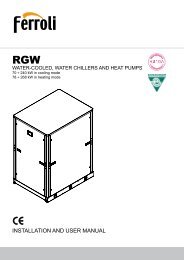
<strong>RHA</strong><br />
AIR COOLED WATER CHILLERS<br />
AND HEAT PUMPS WITH AXIAL FANS<br />
351 ÷ 625 kW in cooling mode<br />
370 ÷ 658 kW in heating mode<br />
ECO-FRIENDLY<br />
REFRIGERANT GAS<br />
TECNICAL MANUAL<br />
1
2<br />
The manufacturer declines all responsibility for any inaccuracies in this manual due to printing or typing errors.<br />
The manufacturer reserves the right to modify the products contents in this catalogue without previous notice.
TABLE OF CONTENTS<br />
THIS MANUAL IS DIVIDED INTO SECTIONS. THEIR NAMES APPEAR IN THE HEADING OF EACH PAGE.<br />
GENERAL SPECIFICATIONS . . . . . . . . . . . . . . . . . . . . . . . . 5<br />
Identification plate of the Unit . . . . . . . . . . . . . . . . . . . . . . 5<br />
Identification code of the unit . . . . . . . . . . . . . . . . . . . . . . 5<br />
Description of the components . . . . . . . . . . . . . . . . . . . . . 6<br />
Version with Desuperheater VD<br />
(available for both IR units and IP units) . . . . . . . . . . . . . 8<br />
ACCESSORIES AND OPTIONAL EQUIPMENT. . . . . . . . . . 9<br />
Mechanical accessories . . . . . . . . . . . . . . . . . . . . . . . . . . 9<br />
Electrical accessories . . . . . . . . . . . . . . . . . . . . . . . . . . . . 11<br />
Mechanical options . . . . . . . . . . . . . . . . . . . . . . . . . . . . . . 11<br />
Electrical options. . . . . . . . . . . . . . . . . . . . . . . . . . . . . . . . 11<br />
GENERAL TECHNICAL specification . . . . . . . . . . . . . . 12<br />
General technical specifications . . . . . . . . . . . . . . . . . . . . 12<br />
nominal performances . . . . . . . . . . . . . . . . . . . . . . . . 13<br />
Standard unit AB - MEDIUM TEMPERATURE PLANT. . . 13<br />
Standard unit AB - LOW TEMPERATURE PLANT . . . . . . 13<br />
Low noise unit AS - MEDIUM TEMPERATURE PLANT . 14<br />
Low noise unit AS - LOW TEMPERATURE PLANT . . . . . 14<br />
Extra low noise unit AX - MEDIUM TEMPERATURE PLANT 15<br />
Extra low noise unit AX - LOW TEMPERATURE PLANT . . . .15<br />
STANDARD PERFORMANCES - IR COOLING UNIT ONLY . .16<br />
Performances - Standard unit AB . . . . . . . . . . . . . . . . . . . 16<br />
Performances - Low noise unit AS . . . . . . . . . . . . . . . . . . 17<br />
Performances - Extra low noise unit AX . . . . . . . . . . . . . . 18<br />
STANDARD PERFORMANCES - IP HEAT PUMP UNITS . . 19<br />
Performances in cooling mode - Standard Unit AB . . . . . 19<br />
Performances in heating mode - Standard Unit AB . . . . . 20<br />
Performances in cooling mode - Low noise Unit AS. . . . . 21<br />
Performances in heating mode - Low noise Unit AS . . . . 22<br />
Performances in cooling mode - Extra low noise Unit AX 23<br />
Performances in heating mode - Extra low noise Unit AX 24<br />
Correction factor for the use of glycol . . . . 25<br />
Correction factor for the use of glycol IN HEATING MODE 25<br />
Correction factor for the use of glycol IN COOLING MODE 25<br />
GENERAL SPECIFICATIONS - BRINE UNIT BR - BP. . . . . 26<br />
Brine Unit BR - BP . . . . . . . . . . . . . . . . . . . . . . . . . . . . . . 26<br />
GENERAL SPECIFICATIONS - Version with Desuperheater<br />
(VD). . . . . . . . . . . . . . . . . . . . . . . . . . . . . . . . . 27<br />
IR COOLING UNIT ONLY . . . . . . . . . . . . . . . . . . . . . . . . . . . 27<br />
Acoustic Version: AB (Standard Unit) . . . . . . . . . . . . . . . 27<br />
Acoustic Version: AS (Low noise Unit) . . . . . . . . . . . . . . . 27<br />
Acoustic Version: AX (Extra low noise Unit) . . . . . . . . . . 27<br />
Performances Version with Desuperheater (VD) . . . . . . . 28<br />
GENERAL SPECIFICATIONS - Version with Desuperheater<br />
(VD) - IP HEAT PUMP UNIT. . . . . . . . . . . . . . 29<br />
Acoustic Version: AB (Standard Unit) . . . . . . . . . . . . . . . 29<br />
Acoustic Version: AS (Low noise Unit) . . . . . . . . . . . . . . . 29<br />
Acoustic Version: AX (Extra low noise Unit) . . . . . . . . . . 29<br />
Performances Version with Desuperheater (VD) . . . . . . . 30<br />
GENERAL SPECIFICATIONS - full heat recovery<br />
unit (Vr) - IP HEAT PUMP UNIT. . . . . . . . . . . . . . . . . . . . . 31<br />
Acoustic Version: AB (Basic Unit) . . . . . . . . . . . . . . . . . . 31<br />
Acoustic Version: AS (Low noise Unit) . . . . . . . . . . . . . . . 31<br />
Acoustic Version: AX (Extra Low noise Unit) . . . . . . . . . . 31<br />
Full Heat recovery unit performances (VR) . . . . . . . . . . . 32<br />
NOISE LEVELS . . . . . . . . . . . . . . . . . . . . . . . . . . . . . . . . . . . 33<br />
Standard Unit AB . . . . . . . . . . . . . . . . . . . . . . . . . . . . . . . 33<br />
Low noise unit AS . . . . . . . . . . . . . . . . . . . . . . . . . . . . . . . 33<br />
Extra low moise unit AX . . . . . . . . . . . . . . . . . . . . . . . . . . 33<br />
OPERATING RANGE . . . . . . . . . . . . . . . . . . . . . . . . . . . . . . 34<br />
Operating range . . . . . . . . . . . . . . . . . . . . . . . . . . . . . . . . 34<br />
Water pressure drop EVAPORATOR . . . . . . . . . . . . 35<br />
Operating range . . . . . . . . . . . . . . . . . . . . . . . . . . . . . . . . 35<br />
Water pressure drop DESUPERHEATER. . . . . . . . . 36<br />
Operating range . . . . . . . . . . . . . . . . . . . . . . . . . . . . . . . . 36<br />
WORKING HEAD OF THE PUMPING MODULE MP AM STD<br />
AND MP SS STD . . . . . . . . . . . . . . . . . . . . . . . . . . . . . . . . . . 37<br />
Operating range . . . . . . . . . . . . . . . . . . . . . . . . . . . . . . . . 37<br />
HIGH WORKING HEAD OF THE PUMPING MODULE MP AM<br />
HP1 AND MP SS HP1 . . . . . . . . . . . . . . . . . . . . . . . . . . . . . . 38<br />
Operating range . . . . . . . . . . . . . . . . . . . . . . . . . . . . . . . . 38<br />
DIMENSIONAL DATA . . . . . . . . . . . . . . . . . . . . . . . . . . . . . . 39<br />
Overall dimensions . . . . . . . . . . . . . . . . . . . . . . . . . . . . . . 39<br />
Description of the components . . . . . . . . . . . . . . . . . . . . . 39<br />
Weight during transport and oparation . . . . . . . . . . . . . . . 40<br />
Minimum space required for operation . . . . . . . . . . . . . . . 40<br />
3
GENERAL SPECIFICATIONS<br />
Identification plate of the Unit<br />
Codice<br />
Code B1 Rev<br />
<strong>Ferroli</strong> Spa<br />
Via Ritonda 78/A<br />
(VR) Italy<br />
The figure on the left depicts the identification plate of the unit, affixed to the outer left-hand side of<br />
the Electric Panel.<br />
A description of the data is given below:<br />
Standard versions<br />
A - Trademark<br />
B - Model<br />
B1- Code<br />
C - Serial number<br />
D - Cooling Capacity<br />
E - Heating Capacity<br />
F -<br />
G -<br />
H -<br />
I -<br />
L -<br />
M -<br />
N -<br />
O -<br />
P -<br />
Q -<br />
R -<br />
S -<br />
Power input in COOLING mode<br />
Power input in HEATING mode<br />
Reference standard<br />
Electric power supply<br />
Maximum load current<br />
Type of refrigerant and charge<br />
Shipping weight of the unit<br />
Sound pressure level at 1m<br />
IP Level Protection<br />
Maximum pressure - High Side<br />
Maximum pressure - Low Side<br />
PED certification authority<br />
Special versions<br />
A - Trademark<br />
B - Model<br />
B1- Code<br />
C - Serial number<br />
D - Cooling Capacity (same as Standard Version of the unit)<br />
E - Heating Capacity<br />
for IR unit, VD version, Recovered Heating Capacity<br />
for IP unit, VD version, Heating Capacity / Recovered Heating Capacity<br />
F - Power input in COOLING mode (same as Standard version of the unit)<br />
G - Power input in HEATING mode<br />
H - Reference standard<br />
I - Electric power supply<br />
L - Maximum load current<br />
M - Type of refrigerant and charge<br />
N - Shipping weight of the unit<br />
O - Sound pressure level at 1m<br />
P - IP Level Protection<br />
Q - Maximum pressure - High Side<br />
R - Maximum pressure - Low Side<br />
S - PED certification authority<br />
NOTE: The identification plate of the Brine Unit (BR - BP) is filled out as<br />
shown in the diagram for the Basic Version of the unit (VB).<br />
Identification code of the unit<br />
The codes that identify the units are listed below and include the sequences of letters that determine the meanings for the various<br />
versions and set-ups.<br />
<strong>RHA</strong> IP - 350.5 - VB - AB - 0 - M - 5<br />
Unit type<br />
IR- units suitable for hydronic plant<br />
installation operating as chillers.<br />
IP- units suitable for hydronic plant<br />
installation operating as heat pumps.<br />
BR- units suitable for hydronic plant<br />
installation with Brine solutions<br />
operating as chillers.<br />
BP- units suitable for hydronic plant<br />
installation with Brine solutions<br />
operating as heat pumps.<br />
Type of Refrigerant<br />
Power Supply<br />
5 - 400V-3ph~50Hz<br />
0 - R410A<br />
Unit model<br />
N° Compressor<br />
Unit version<br />
VB - Standard unit<br />
VD- Desuperheater unit<br />
VR- Full heat recovery unit<br />
Acoustic Version<br />
AB - Standard unit<br />
AS - Low noise unit<br />
AX - Extra low noise unit<br />
Operating range<br />
M - Medium temperature. Units are<br />
suitable to be installed in temperate<br />
climate sites.<br />
A - High temperature. Units are suitable<br />
to be installed in tropical climate sites.<br />
The available special versions are described below:<br />
VB: Standard unit.<br />
VD: Version with Desuperheater (available forboth IR units and IP units)<br />
Produces cold water in the same way as the standard version plus hot water from 30 to 70°C at the same time. This is achieved by installing a<br />
water-refrigerant gas heat exchanger between the compressor and coils in order to recover 20 to 25% of the heating capacity that would otherwise<br />
be dispersed in the air.<br />
It helps to remind that hot water production is possible only in combination with cold-hot water production in the main heat exchanger and it is<br />
subordinated by it.<br />
VR: Total Heat Recovery version<br />
Produces cold water as in the standard version plus hot water at a temperature of 35 to 55°C at the same time. This is achieved thanks to a waterrefrigerant<br />
gas heat exchanger that totally recovers the heating capacity that would otherwise be dispersed in the air. The total heat recovery<br />
function is enabled and disabled by means of a valve on the compressor delivery of each circuit: when the temperature of the water that enters<br />
the recuperator drops, the valve switches the hot gas flow from the condensing coils to the recovery heat exchanger. On the other hand, when the<br />
temperature of the water reaches the set-point, the valve shuts off the heat recuperator and switches the hot gas flow to the condensing coils.<br />
It helps to remind that hot water production is possible only in combination with cold water production in the main heat exchanger and it is subordinated<br />
by it.<br />
5
GENERAL SPECIFICATIONS<br />
Description of the components<br />
1. Fans. These are the helical type with scythe-shaped blades to increase the efficiency and reduce the noise level. The fans are<br />
directly coupled to the single-phase motor by means of an external rotor. Thermal protection against operating faults is installed inside<br />
the winding. As standard they are equipped with continuous adjustment of axial fans rotating speed in order to allow the units to<br />
operate both with low outdoor temperature in cooling mode and with high outdoor temperature in heating mode.<br />
2. Electric control and monitoring panel.<br />
It is housed in a cabinet made of adequately thick painted sheet metal suitable for outdoor installation (protection degree IP 54). The<br />
panel comprises the following main components:<br />
- Main door-locking circuit-breaker.<br />
- Fuse holders with protection fuses for each compressor.<br />
- Fuse holders with protection fuses for the antifreeze heater.<br />
- Fuse holders and protection fuses for the fans (accessories).<br />
- Fan control contactors.<br />
- Insulating and safety transformer to power the auxiliaries, protected with fuses.<br />
- Basic monitoring board with microprocessor<br />
Control system main functions:<br />
temperature control of the water produced by the unit, compressor and pump operating hour counter, timing and cycling of start-ups,<br />
input parameters by keyboard, alarms management, smart defrosting control and operating mode change (only IP unit), dynamic setpoint<br />
(climatic control), scheduling and integrative heaters control ATC. If you installed the hydronic kit these functions are enabled:<br />
antifreeze with pump, start-up cycle after prolonged inactivity (anti-sticking), if the hydronic kit installed has 2 pumps there is a cycling<br />
between each pump to ensure an equivalent lifetime.<br />
Digital input functions: low pressure, high pressure, high temperature on compressor supply, phase presence and sequence monitoring<br />
device on power supply, differential water pressure control, compressors thermal protection, fans thermal protection, pumps<br />
thermal protection (only if installed MP accessory), remote ON/OFF and remote operating mode change E/I (only IP unit), demand<br />
limit, double Set-point.<br />
Digital output functions: compressor start-up, pump start-up (only with MP accessory), plate heat exchanger electrical heater,<br />
remote general alarm, 4-way valve (only IP unit), additional heating management, available digital contact on compressors running.<br />
Analogic input functions: in and out water temperature, coil temperature probe, external air temperature probe.<br />
Analogic output functions: continuous adjustment of axial fans rotating speed (if installed).<br />
Moreover the controller allows:<br />
- Alarm history (max 50m alarms managed with FIFO logic)<br />
- Time scheduling (daily and weekly)<br />
- Precise control of the water leaving temperature<br />
- ATC (Advanced Temperature Control) prevention of the block of the unit: In case of critical conditions the machine does not stop<br />
but is able to regulate itself and provide the maximum power that can be generated in those conditions with the compressors working<br />
inside the admissible limits.<br />
-Demand Limit by Digital Input and/or by Analog Input (4-20mA)<br />
-Double Set Point by Digital Input<br />
-Connection to BMS (supervision systems) through serial port RS 485 and MODBUS protocol<br />
3. User interfacing terminal with display.<br />
Control panel: composed of the instrument’s front panel, equipped with an LCD display, three indicator LEDs, and one joystick buttons<br />
and three function button, it enables viewing and/or checking the operating mode and parameters, resources and complete alarm<br />
diagnostics.<br />
In particular, it enables:<br />
· Managing alarm situations<br />
· Checking the status of resources.<br />
KEY<br />
1.Display<br />
2. Alarms LED<br />
1 2 3 4<br />
3. LED for communication between the motherboard governing<br />
the unit and the keypad<br />
4. Power supply LED<br />
5. Joystick Menu Button<br />
6. Function Button<br />
6<br />
5<br />
4. Compressors. They are the SCROLL type with orbiting coil equipped with built-in thermal protection and oil heater. The version<br />
unit AS and AX includes: a soundproofing jacket for the compressors, acoustic cladding for the entire compressor compartment to<br />
reduce the noise level and continuous adjustment of axial fans rotating speed. All units are equipped with five/six compressors connected<br />
in parallel (2 cooling circuits) which can operate at the same time (100% cooling power) or individually (17-33-50-67-83-100%<br />
of the cooling power), thus adapting to the different thermal loads of the system supplied.<br />
5. Frame structure made of galvanized sheet metal panels coated with polyurethane powder paint to ensure maximun protection<br />
against adverse weather conditions.<br />
6. Evaporator made of brazed stainless steel plates (AISI 316). It is installed in a shell of heat-insulating material to prevent the<br />
formation of condensation and heat exchanges towards the outside. Standard supply also includes antifreeze heater a differential<br />
pressure switch on the water circuit to avoid the risk of freezing if the water flow is shut off for some reason.<br />
6
GENERAL SPECIFICATIONS<br />
7. Condensing coils, the aluminium finned pack type with shaped profile to increase the heat exchange coefficient and with copper<br />
pipes arranged in staggered rows. A sub-cooling section is integrated into the lower part.<br />
8. Covering panels, made of galvanized sheet metal coated with polyurethane powder paint to ensure maximun protection against<br />
adverse weather conditions<br />
9.One-way valves (IP unit only), allowing the coolant to pass into the appropriate exchangers, depending on the operating cycle.<br />
10. 4-way cycle reversal valve (IP unit only), reverses the flow direction of the gas as the summer/winter operating mode is changed.<br />
Hydraulic and cooling circuit components (per circuit)<br />
11. Safety valve. Installed on the delivery pipe of the compressors, this operates if extreme faults should occur in the plant.<br />
12. Fluid tap. Ball type, this allows the gas flow on the fluid line to be turned on and off. Along with the tap on the compressor delivery,<br />
it allows the components of the fluid line to be subjected to extraordinary maintenance work and the compressors to be replaced if<br />
necessary (without discharging the coolant from the unit): pump down.<br />
13. Compressor delivery tap. Ball type, allows the gas delivered to the compressors to be turned on and off.<br />
14. Dehydrator filter. Mechanical cartridge type. Retains impurities and traces of moisture in the circuit.<br />
15. Fluid and humidity indicator. Signals when fluid passes through the circuit, indicating that the coolant charge is correct. The<br />
fluid indicator light also indicates the amount of moisture in the coolant by changing colour.<br />
16. Low pressure switch. With fixed setting. It is installed on the suction pipe and blocks the compressors if the operating pressures<br />
drop below the tolerated values. Automatically resets as the pressure increases. If it activates frequently, the unit will block and can<br />
only be restarted by resetting via the user interface terminal.<br />
17. High pressure switch (n°3). With fixed setting. Are is installed on the delivery pipe and blocks the compressors if the operating pressures<br />
exceed the tolerated values. If it activates, the unit will block and can only be restarted by resetting via the user interface terminal.<br />
18. Electronic expansion valve. This supplies the evaporator correctly, keeping the selected superheating degree at a steady level.<br />
19. Pressure taps: 1/4 “ SAE (7/16” UNF) type with flow regulator. Allow the operating pressure of the system to be measured:<br />
compressor delivery, lamination component inlet, compressor intake.<br />
20. Pressure taps: 5/16 “ SAE type with flow regulator. Allow the charge/discharge of the gas from the system, precisely from compressor<br />
outlet an expansion valve inlet.<br />
21. Electrical heating elements to heat the compressor oil. “Belt” type. These activate when the compressor turns off and keep<br />
the temperature of the oil sufficiently high so as to prevent coolant from migrating during these pauses.<br />
22. Fluid receiver (IP unit only), this is a plenum tank that accounts for variations to the coolant charge the machine must supply<br />
as the summer/winter operating mode varies.<br />
23. Fluid separator (IP unit only), on the compressor intake to protect against possible fluid back-flows.<br />
24. Water differential pressure switch. This is standard supply and is installed on the connections between the water inlet and<br />
outlet of the exchanger. It stops the unit if it activates.<br />
7
GENERAL SPECIFICATIONS<br />
Version with Desuperheater VD (available for both IR units and IP units)<br />
Hydraulic and chilling circuit components:<br />
1. Desuperheater. Specially designed for the specific version. Plate type, made of stainless steel (AISI 316).<br />
It is installed within a shell of thermal barrier insulating material to prevent heat exchanges towards the outside. Standard supply also<br />
includes an electric antifreeze heater to prevent the parts from freezing during the winter, when the system remains at a standstill (if<br />
not drained).<br />
2. Water safety valve.On the heat recovery inlet pipe. It acts whenever faulty service leads to an operating pressure in the plumbing<br />
system that exceeds the valve opening value (Fig.1).<br />
3. Water drain cock for emptying the exchangers and pipes of the machine dedicated to heat recovery (Fig. 1).<br />
4. Air vent. Accessed by removing the front panels. It consists of a manually operated valve installed in the highest part of the water<br />
pipes. To use in conjunction with the water drain cocks situated in the rear part of the unit, for emptying the exchangers and pipes<br />
dedicated to heat recovery.<br />
8
ACCESSORIES AND OPTIONAL EQUIPMENT<br />
Mechanical accessories<br />
NOTE: The accessories can be of the following type:<br />
(M): only installed in the factory.<br />
(F): supplied for installation by the customer.<br />
MP. Hydronic Kit (M). Consists of:<br />
1 On-off ball valves. Turn components such as the water filter, surge chamber and pump on and off when they require routine or extraordinary<br />
maintenance.<br />
2 Metal gauze water filter. Can be turned on and off and inspected. It is installed on the pump delivery side. Prevents machining residues (dust,<br />
swarf, etc.) in the water pipes from entering the plate-type heat exchanger.<br />
3 Hydraulic pump. Circulates water around the system. The pumps have a low/high head and suit the majority of installation requirements. The<br />
pumps are safeguarded by a magnetothermics installed in the chiller’s electric panel.<br />
4 Surge chamber. This is a closed, diaphragm type chamber. It absorbs the variations in the volumes of water in the system caused by temperature<br />
variations.<br />
5 Water filling. Manual function with control positioned on the side of the unit opposite the electric panel and turned on and off by a cock that can<br />
be accessed by removing the rear panel.<br />
6 Water pressure gauge. Connected to the water fill pipe. Displays the pressure of the water in the system.<br />
7 Water safety valve.<br />
8 Water outlet.<br />
9 Air vent.<br />
10 Antifreeze heater connection (RAG accessory).<br />
To ensure a continuous operation, an anti-freeze with pump function (based on a reading from the output water probe) and starting cyclic (antisticking)<br />
after prolonged inactivity are enabled; if the hydronic kit has 2 pumps, the second, mounted in parallel to the first, can be activated in case<br />
of failure of the first and will also include a cycling period to guarantee to each pump an equivalent operating time.<br />
MP. Hydronic Kit.<br />
MP : Hydronic Kit with 1 (M1P) o 2 (M2P) Pumps: (The second pump, mounted in parallel to the first, allows to have a spare pump to be activated<br />
in case of failure of the first). Besides the pumps, this accessory is equipped with all the hydraulic components (water filter, expansion tank, on-off<br />
valves, water pressure gauge, air vent, water outlet) required for complete installation and easy maintenance.<br />
Different water accumulation tank configurations are therefore available in combination with the Hydronic Kit accessory:<br />
MP AM 2P STD: Accumulation on the Plant Delivery side (Standard) (A) : The pump draws water from the system, sends it to the plate exchanger<br />
and from thence to the inertial accumulation tank. During normal operating conditions, the pump in this configuration is able to provide a residue<br />
head from 86 to 150 kPa (from 9 to 15 m.w.c.) for the circulating water.<br />
MP AM 2P HP1: Accumulation on the Plant Delivery side (High) (B) .: The pump draws water from the system, sends it to the plate exchanger and<br />
from thence to the inertial accumulation tank. During normal operating conditions, the pump in this configuration is able to provide a residue head<br />
from 198 to 255 kPa (from 20 to 25 m.w.c.) for the circulating water.<br />
MP PS 2P STD: Accumulation pre-engineered for the primary and secondary circuit : The sole function of the pump is to circulate the water<br />
around the primary circuit: this circuit includes the accumulation tank and plate exchanger (chiller water circuit). The installer must mount the pumping<br />
section relative to the secondary circuit formed by the accumulation tank (with the pre-engineered wet connections) and the system served.<br />
No high working head version available.<br />
MP SS 2P STD: Hydronic Kit without Water Storage Tank (Standard) (A) . The pump draws water from the system, sends it to the plate heat exchanger<br />
and returns it to the system. During normal operating conditions, the pump in this configurations can provide a residue head from 86 to<br />
150 kPa (from 9 to 15 m w.c.).<br />
MP SS 2P HP1: Hydronic Kit without Water Storage Tank (High Working Head) (B) . The pump draws water from the system, sends it to the plate<br />
heat exchanger and returns it to the system. During normal operating conditions, the pump in this configurations can provide a residue head from<br />
198 to 255 kPa (from 20 to 25 m w.c.).<br />
Notes:<br />
(A): For the working head values depending on the water flow rate, consult the Standard Working Head MP AM STD graph.<br />
(B): For the working head values depending on the water flow rate, consult the High Working Head MP AM HP1 graph.<br />
SAA- Water Storage tank (M). Painted steel water storage tank reduces compressor startup frequency and temperature fluctuation on water side. It<br />
is coated with thermo insulated material to avoid air condensing and losses due to heat transfer. It is available on delivery side and also for primarysecondary<br />
hydraulic circuit interface.<br />
Water storage tank. It consists of:<br />
Water draining. On-off action by means of a cock that can be accessed by removing the rear panel, positioned on the side of the unit opposite<br />
to the electric panel.<br />
Air vent. Accessed by removing the rear panel positioned on the side of the unit opposite to the electric panel. It consists of a manually operated<br />
valve installed on the highest part of the wet pipes.<br />
Antifreeze heater connection. 1”1/4 female threaded connection pre-engineered for installation of the antifreeze heater (RAG accessory).<br />
Water safety valve, on the rear part of the tank. It acts whenever faulty service leads to an operating pressure in the hydraulic circuit that exceeds<br />
the valve opening value.<br />
KT - the following kits are available (this accessory is mandatory if the Hydronic Kit is not installed).<br />
- Victaulic connection kit. This accessory consists of steel pipes insulated with thermal barrier material and allows the water inlet/outlet to be<br />
connected straight inside the unit.<br />
- Complete pipe kit. This accessory consists of steel pipes insulated with thermal barrier material and allows the water inlet/outlet connection to<br />
be routed to the machine.<br />
- Water storage tank pipe kit. This accessory consists of steel pipes insulated with thermal barrier material and allows the water inlet/outlet connection<br />
to be routed to the machine.<br />
NB: YOU CAN CHOOSE ONLY ONE KIT.<br />
GP- Coil protection grid (M). Protects external surface of the finned coils.<br />
GM- Pressure gauges kit (M). 4 pressure gauges allow visualization of high and low refrigerant gas pressure.<br />
AVG- Rubber vibration dampers (F). Reduce vibrations transmitted to the floor by compressors and fans during normal operating conditions (until 85%).<br />
AVM- Spring vibration dampers (F).Reduce vibrations transmitted to the floor by compressors and fans during normal operating conditions (until 90%).<br />
9
ACCESSORIES AND OPTIONAL EQUIPMENT<br />
Victaulic connection kit COMPLETE PIPE KIT Water storage tank pipe kit<br />
M1P AM 2P STD M1P AM 2P HP1 M1P PS 2P STD<br />
M2P AM 2P STD M2P AM 2P HP1 M2P PS 2P STD<br />
M1P SS 2P STD<br />
M1P SS 2P HP1<br />
M2P SS 2P STD<br />
M2P SS 2P HP1<br />
10
ACCESSORIES AND OPTIONAL EQUIPMENT<br />
Electrical accessories<br />
TP - Low and High pressure transducers (M). Allow the display of the suction and discharge pressures of compressors. Their presence<br />
activates an advanced defrost and condensation control logic and the ATC (Advanced Temperature Control) to prevent high pressure alarm<br />
due to high external air temperature.<br />
RAG- Storage tank electrical heater (F). Keeps water in storage tank above freezing point to avoid risk of icing during winter stops it is<br />
activated together with plate heat exchanger electrical heater.<br />
TAT- High Temperature Thermostat (M). Two thermostats in series on compressors outlet pipes preserve operation not allowing temperature<br />
to rise up than a specified non adjustable value.<br />
CR- Remote control panel (F). Replies every control and visualization of the onboard control panel.<br />
INT- Serial interface (M). Allows serial communication on RS485 by MODBUS protocol.<br />
MTC - Magnetothermic switch (M). Magnetothermic switch on all loads place of fuses.<br />
SS - Soft Starter (M). Soft starter on compressors allow to reduce to about a 60% nominal inrush current.<br />
FLS - Flow switch (F). Paddle flow switch on the water circuit to avoid the risk of freezing if the water flow is shut off for some reason.<br />
RIF - Capacitors for power factor corrections (M). Capacitors for power factor corrections increase power factor cos φ (> 0.91) and reduce<br />
power input.<br />
CSF - Voltage monitor and sequence meter (M). The device enables control of the correct sequence of power phases and the lack of any<br />
phases.<br />
KOP - Programmer clock (M). Allows the unit to be turned on and off depending on the programmed time setting (up to 14 switching actions<br />
can be programmed as required throughout the 7 days of the week).<br />
DCC - Head pressure control (M). (as standard for Low Noise unit AS and for eXtra Low Noise unit AX).<br />
The device is made by 2 electrical drivers that, by means of phase cutting, control the fans speed rotation, with the scope of mantaining the<br />
condensation pressure inside the correct operating limits.<br />
Mechanical options<br />
Special finned heat exchangers<br />
• Coils with copper fins<br />
• Coils with tin-coated copper fins<br />
• Coils with aluminium fins with acrylic, epoxy or hydrofilic coating.<br />
Electrical options<br />
Other power source voltage rating (contact our technical department).<br />
11
GENERAL TECHNICAL specification<br />
General technical specifications<br />
MODELS 350.5 390.6 440.6 490.6 560.6 630.6 UM<br />
Power supply 400-3-50 V-ph-Hz<br />
Refrigerant type R410A -<br />
Refrigeration circuits 2 N°<br />
Compressor specifications<br />
Type scroll -<br />
Quantity 5 6 N°<br />
Oil charge CP1 6.8 6.8 6.8 6.3 6.3 6.3 l<br />
Oil charge CP2 6.8 6.8 6.8 6.3 6.3 6.3 l<br />
Oil charge CP3 6.8 6.8 6.8 6.3 6.3 6.3 l<br />
Oil charge CP4 6.3 6.8 6.3 6.3 6.3 6.3 l<br />
Oil charge CP5 6.3 6.8 6.3 6.3 6.3 6.3 l<br />
Oil charge CP6 - 6.8 6.3 6.3 6.3 6.3 l<br />
Load steps<br />
0 / 20 / 40 / 60<br />
/ 80 / 100<br />
0 / 16.7 / 33.3 / 50 / 66.7 / 83.3 / 100 %<br />
Heat Exchanger<br />
Type Brazed plates -<br />
Quantity 1 N°<br />
Total water capacity 27.5 27.5 34.7 34.7 53.6 53.6 l<br />
Coils specifications<br />
Type Aluminum fins and copper tubes -<br />
Quantity 2 N°<br />
Total area 9.28 9.28 9.28 9.28 11.14 11.14 m 2<br />
Fan specifications<br />
Type Axial -<br />
Quantity 8 8 10 10 12 12 N°<br />
Maximum rotation speed<br />
Total air flow rate<br />
Data referred to standard operating condition.<br />
(SAA): with storage tank<br />
AB<br />
AS<br />
AX<br />
AB<br />
AS<br />
AX<br />
900 rpm<br />
750 rpm<br />
600 rpm<br />
165840 159520 207300 199400 248760 239280 m 3 /h<br />
138200 132933 172750 166167 207300 199400 m 3 /h<br />
110560 106347 138200 132933 165840 159520 m 3 /h<br />
Power input 14.4 14.4 18.0 18.0 21.6 21.6 kW<br />
Water Storage Tank (SAA accessory)<br />
Water volume 700 l<br />
Surge chamber volume 24 l<br />
Safety valve setting 600 kPa<br />
Surge chamber default pressure 150 kPa<br />
Max. operating pressure 800 kPa<br />
Electrical specifications<br />
Units without pumping module<br />
MODELS 350.5 390.6 440.6 490.6 560.6 630.6 UM<br />
Total maximum load current [ FLA ] 233 302 355 399 451 494 A<br />
Total maximum power input [ FLI ] 139 182 211 237 272 304 kW<br />
Total maximum starting current [ MIC ] 422 529 605 649 771 815 A<br />
Units with pumping module MP PS STD (1 or 2 pumps)<br />
Total maximum load current [ FLA ] 245 314 376 420 472 515 A<br />
Total maximum power input [ FLI ] 146 189 224 250 285 317 kW<br />
Total maximum starting current [ MIC ] 434 541 626 670 792 835 A<br />
Units with pumping module MP AM STD and MP SS STD (1 or 2 pumps)<br />
Total maximum load current [ FLA ] 247 316 376 420 472 515 A<br />
Total maximum power input [ FLI ] 147 190 224 250 285 317 kW<br />
Total maximum starting current [ MIC ] 436 543 626 670 792 835 A<br />
Units with pumping module MP AM HP1 and MP SS HP1 (1 or 2 pumps)<br />
Total maximum load current [ FLA ] 254 323 382 426 478 521 A<br />
Total maximum power input [ FLI ] 152 195 227 253 288 320 kW<br />
Total maximum starting current [ MIC ] 442 550 632 676 798 842 A<br />
12
nominal performances<br />
Standard unit AB - MEDIUM TEMPERATURE PLANT<br />
IR<br />
IP<br />
MOD. 350.5 390.6 440.6 490.6 560.6 630.6 UM<br />
Cooling mode A35W7 (source: air 35°C d.b. / system: water in 12°C out 7°C)<br />
Cooling capacity (E) 351 374 439 494 558 625 kW<br />
Compressor power input 105 114 131 151 168 191 kW<br />
Total power input 120 128 149 169 189 213 kW<br />
EER (E) 2.93 2.92 2.95 2.92 2.95 2.93 -<br />
ESEER (E) 4.10 4.09 4.12 4.09 4.13 4.11 -<br />
Water flow rate 16.8 17.9 21.0 23.6 26.7 29.9 l/s<br />
Water pressure drop (E) 47 54 48 60 45 56 kPa<br />
Cooling mode A35W7 (source: air 35°C d.b. / system: water in 12°C out 7°C)<br />
Cooling capacity (E) 341 364 426 480 540 608 kW<br />
Compressor power input 104.0 112.0 130.0 149.0 166.0 189.0 kW<br />
Total power input 118.0 127.0 148.0 167.0 187.0 211.0 kW<br />
EER (E) 2.89 2.87 2.88 2.87 2.89 2.88 -<br />
ESEER (E) 4.05 4.01 4.03 4.02 4.04 4.03 -<br />
Water flow rate 16.3 17.4 20.4 22.9 25.8 29.0 l/s<br />
Water pressure drop (E) 45 51 45 57 42 53 kPa<br />
Heating mode A7W45 (source: air 7°C d.b. 6°C w.b. / system: water in 40°C out 45°C)<br />
Heating capacity (E) 370 393 456 516 576 658 kW<br />
Compressor power input 106.0 114.0 130.0 151.0 166.0 195.0 kW<br />
Total power input 120.0 128.0 148.0 169.0 188.0 217 kW<br />
COP (E) 3.08 3.07 3.08 3.05 3.06 3.03 -<br />
Water flow rate 17.7 18.8 21.8 24.7 27.5 31.4 l/s<br />
Water pressure drop (E) 53 59 51 66 48 62 kPa<br />
Heating mode A2W45 (source: air 2°C d.b. 1°C w.b. / system: water in 40°C out 45°C)<br />
Heating capacity 337 358 415 470 524 599 kW<br />
Compressor power input 104.4 112.3 128.1 148.7 163.5 192.1 kW<br />
Total power input 118.8 126.7 146.1 166.7 185.1 213.7 kW<br />
COP 2.84 2.83 2.84 2.82 2.83 2.80 -<br />
Water flow rate 16.1 17.1 19.8 22.4 25.0 28.6 l/s<br />
Water pressure drop 43 49 42 54 39 51 kPa<br />
(E): Data declared according to EUROVENT LCP certification programme. The values are for units without options and accessories.<br />
Standard unit AB - LOW TEMPERATURE PLANT<br />
IR<br />
IP<br />
MOD. 350.5 390.6 440.6 490.6 560.6 630.6 UM<br />
Cooling mode A35W18 (source: air 35°C d.b. / system: water in 23°C out 18°C)<br />
Cooling capacity 449 479 562 632 714 800 kW<br />
Compressor power input 111.3 120.8 138.9 160.1 178.1 202.5 kW<br />
Total power input 125.7 135.2 156.9 178.1 199.7 224 kW<br />
EER 3.57 3.54 3.58 3.55 3.58 3.57 -<br />
Water flow rate 21.5 22.9 26.8 30.2 34.1 38.2 l/s<br />
Water pressure drop 77 88 78 98 73 91 kPa<br />
Cooling mode A35W18 (source: air 35°C d.b. / system: water in 23°C out 18°C)<br />
Cooling capacity 436 466 545 614 691 778 kW<br />
Compressor power input 110.2 118.7 137.8 157.9 176.0 200.3 kW<br />
Total power input 124.6 133.1 155.8 175.9 197.6 222 kW<br />
EER 3.50 3.50 3.50 3.49 3.50 3.50 -<br />
Water flow rate 20.9 22.3 26.1 29.4 33.0 37.2 l/s<br />
Water pressure drop 73 83 74 93 68 87 kPa<br />
Heating mode A7W35 (source: air 7°C d.b. 6°C w.b. / system: water in 30°C out 35°C)<br />
Heating capacity 392 417 483 547 611 697 kW<br />
Compressor power input 90.1 96.9 110.5 128.4 141.1 165.8 kW<br />
Total power input 104.5 111.3 128.5 146.4 162.7 187.4 kW<br />
COP 3.75 3.75 3.76 3.74 3.76 3.72 -<br />
Water flow rate 18.7 19.9 23.1 26.1 29.2 33.3 l/s<br />
Water pressure drop 59 66 58 73 54 70 kPa<br />
Heating mode A2W35 (source: air 2°C d.b. 1°C w.b. / system: water in 30°C out 35°C)<br />
Heating capacity 350 372 432 488 545 623 kW<br />
Compressor power input 85.1 91.5 104.4 121.2 133.3 156.5 kW<br />
Total power input 99.5 105.9 122.4 139.2 154.9 178.1 kW<br />
COP 3.52 3.51 3.53 3.51 3.52 3.50 -<br />
Water flow rate 16.7 17.8 20.6 23.3 26.0 29.8 l/s<br />
Water pressure drop 47 53 46 59 43 56 kPa<br />
13
nominal performances<br />
Low noise unit AS - MEDIUM TEMPERATURE PLANT<br />
IR<br />
IP<br />
MODELLO 350.5 390.6 440.6 490.6 560.6 630.6 UM<br />
Cooling mode A35W7 (source: air 35°C d.b. / system: water in 12°C out 7°C)<br />
Cooling capacity (E) 337 359 421 474 536 600 kW<br />
Compressor power input 113.0 123.0 141.0 163.0 181.0 206.0 kW<br />
Total power input 127.0 137.0 159.0 181.0 203.0 228 kW<br />
EER (E) 2.65 2.62 2.65 2.62 2.64 2.63 -<br />
ESEER (E) 3.71 3.67 3.71 3.67 3.70 3.68 -<br />
Water flow rate 16.10 17.20 20.10 22.6 25.6 28.7 l/s<br />
Water pressure drop (E) 43 50 44 55 41 52 kPa<br />
Cooling mode A35W7 (source: air 35°C d.b. / system: water in 12°C out 7°C)<br />
Cooling capacity (E) 327 349 409 461 518 584 kW<br />
Compressor power input 112.0 121.0 140.0 161.0 179.0 204.0 kW<br />
Total power input 126.0 135.0 158.0 179.0 201.0 226 kW<br />
EER (E) 2.60 2.59 2.59 2.58 2.58 2.58 -<br />
ESEER (E) 3.63 3.62 3.62 3.61 3.61 3.62 -<br />
Water flow rate 15.60 16.70 19.50 22.00 24.7 27.9 l/s<br />
Water pressure drop (E) 41 47 41 52 38 49 kPa<br />
Heating mode A7W45 (source: air 7°C d.b. 6°C w.b. / system: water in 40°C out 45°C)<br />
Heating capacity (E) 355 377 438 495 553 632 kW<br />
Compressor power input 101.0 108.0 124.0 143.0 158.0 185.0 kW<br />
Total power input 115.0 122.0 142.0 161.0 180.0 207.0 kW<br />
COP (E) 3.09 3.09 3.08 3.07 3.07 3.05 -<br />
Water flow rate 17.00 18.00 20.9 23.7 26.4 30.2 l/s<br />
Water pressure drop (E) 48 54 47 61 44 57 kPa<br />
Heating mode A2W45 (source: air 2°C d.b. 1°C w.b. / system: water in 40°C out 45°C)<br />
Heating capacity 323 343 399 450 503 575 kW<br />
Compressor power input 99.5 106.4 122.1 140.9 155.6 182.2 kW<br />
Total power input 113.9 120.8 140.1 158.9 177.2 203.8 kW<br />
COP 2.84 2.84 2.85 2.83 2.84 2.82 -<br />
Water flow rate 15.43 16.39 19.04 21.52 24.0 27.5 l/s<br />
Water pressure drop 40 45 39 50 36 47 kPa<br />
(E): Data declared according to EUROVENT LCP certification programme. The values are for units without options and accessories.<br />
Low noise unit AS - LOW TEMPERATURE PLANT<br />
IR<br />
IP<br />
14<br />
MODELLO 350.5 390.6 440.6 490.6 560.6 630.6 UM<br />
Cooling mode A35W18 (source: air 35°C d.b. / system: water in 23°C out 18°C)<br />
Cooling capacity 431 460 539 607 686 768 kW<br />
Compressor power input 119.8 130.4 149.5 172.8 191.9 218 kW<br />
Total power input 134.2 144.8 167.5 190.8 213.5 240 kW<br />
EER 3.21 3.18 3.22 3.18 3.21 3.20 -<br />
Water flow rate 20.61 22.0 25.7 29.0 32.8 36.7 l/s<br />
Water pressure drop 71 81 71 91 68 84 kPa<br />
Cooling mode A35W18 (source: air 35°C d.b. / system: water in 23°C out 18°C)<br />
Cooling capacity 419 447 524 590 663 748 kW<br />
Compressor power input 118.7 128.3 148.4 170.7 189.7 216 kW<br />
Total power input 133.1 142.7 166.4 188.7 211.3 238 kW<br />
EER 3.15 3.13 3.15 3.13 3.14 3.14 -<br />
Water flow rate 20.00 21.3 25.0 28.2 31.7 35.7 l/s<br />
Water pressure drop 67 76 67 86 63 80 kPa<br />
Heating mode A7W35 (source: air 7°C d.b. 6°C w.b. / system: water in 30°C out 35°C)<br />
Heating capacity 376 400 464 525 586 670 kW<br />
Compressor power input 85.9 91.8 105.4 121.6 134.3 157.3 kW<br />
Total power input 100.3 106.2 123.4 139.6 155.9 178.9 kW<br />
COP 3.75 3.77 3.76 3.76 3.76 3.75 -<br />
Water flow rate 17.98 19.09 22.2 25.1 28.0 32.0 l/s<br />
Water pressure drop 54 61 53 68 49 64 kPa<br />
Heating mode A2W35 (source: air 2°C d.b. 1°C w.b. / system: water in 30°C out 35°C)<br />
Heating capacity 336 357 415 468 523 598 kW<br />
Compressor power input 81.1 86.7 99.5 114.8 126.8 148.5 kW<br />
Total power input 95.5 101.1 117.5 132.8 148.4 170.1 kW<br />
COP 3.52 3.53 3.53 3.52 3.52 3.52 -<br />
Water flow rate 16.05 17.05 19.80 22.4 25.0 28.6 l/s<br />
Water pressure drop 43 49 42 54 39 51 kPa
nominal performances<br />
Extra low noise unit AX - MEDIUM TEMPERATURE PLANT<br />
IR<br />
IP<br />
MODELLO 350.5 390.6 440.6 490.6 560.6 630.6 UM<br />
Cooling mode A35W7 (source: air 35°C d.b. / system: water in 12°C out 7°C)<br />
Cooling capacity (E) 330 352 413 464 525 588 kW<br />
Compressor power input 117.0 127.0 145.0 168.0 186.0 212.0 kW<br />
Total power input 131.0 141.0 163.0 186.0 208.0 234 kW<br />
EER (E) 2.52 2.50 2.53 2.49 2.52 2.51 -<br />
ESEER (E) 3.53 3.50 3.55 3.49 3.53 3.52 -<br />
Water flow rate 15.80 16.80 19.70 22.2 25.1 28.1 l/s<br />
Water pressure drop (E) 42 47 42 53 40 49 kPa<br />
Cooling mode A35W7 (source: air 35°C d.b. / system: water in 12°C out 7°C)<br />
Cooling capacity (E) 321 342 400 451 508 572 kW<br />
Compressor power input 115.0 124.0 144.0 165.0 184.0 210.0 kW<br />
Total power input 129.0 138.0 162.0 183.0 206.0 232 kW<br />
EER (E) 2.49 2.48 2.47 2.46 2.47 2.47 -<br />
ESEER (E) 3.48 3.47 3.46 3.45 3.45 3.45 -<br />
Water flow rate 15.30 16.30 19.10 21.50 24.3 27.3 l/s<br />
Water pressure drop (E) 39 45 39 50 37 47 kPa<br />
Heating mode A7W45 (source: air 7°C d.b. 6°C w.b. / system: water in 40°C out 45°C)<br />
Heating capacity (E) 352 373 433 490 547 625 kW<br />
Compressor power input 98.6 106.0 121.0 140.0 154.0 181.0 kW<br />
Total power input 113.0 120.0 139.0 158.0 176.0 203.0 kW<br />
COP (E) 3.12 3.11 3.12 3.10 3.11 3.08 -<br />
Water flow rate 16.80 17.80 20.70 23.4 26.1 29.9 l/s<br />
Water pressure drop (E) 47 53 46 59 43 56 kPa<br />
Heating mode A2W45 (source: air 2°C d.b. 1°C w.b. / system: water in 40°C out 45°C)<br />
Heating capacity (E) 320 339 394 446 498 569 kW<br />
Compressor power input 97.1 104.4 119.2 137.9 151.7 178.3 kW<br />
Total power input 111.5 118.8 137.2 155.9 173.3 199.9 kW<br />
COP (E) 2.87 2.85 2.87 2.86 2.87 2.85 -<br />
Water flow rate 15.30 16.22 18.83 21.30 23.8 27.2 l/s<br />
Water pressure drop (E) 39 44 38 49 36 46 kPa<br />
(E): Data declared according to EUROVENT LCP certification programme. The values are for units without options and accessories.<br />
Extra low noise unit AX - LOW TEMPERATURE PLANT<br />
IR<br />
IP<br />
MODELLO 350.5 390.6 440.6 490.6 560.6 630.6 UM<br />
Cooling mode A35W18 (source: air 35°C d.b. / system: water in 23°C out 18°C)<br />
Cooling capacity 422 451 529 594 672 753 kW<br />
Compressor power input 124.0 134.6 153.7 178.1 197.2 225 kW<br />
Total power input 138.4 149.0 171.7 196.1 219 246 kW<br />
EER 3.05 3.03 3.08 3.03 3.07 3.06 -<br />
Water flow rate 20.18 21.5 25.3 28.4 32.1 36.0 l/s<br />
Water pressure drop 68 77 69 87 65 81 kPa<br />
Cooling mode A35W18 (source: air 35°C d.b. / system: water in 23°C out 18°C)<br />
Cooling capacity 411 438 512 577 650 732 kW<br />
Compressor power input 121.9 131.4 152.6 174.9 195.0 223 kW<br />
Total power input 136.3 145.8 170.6 192.9 217 244 kW<br />
EER 3.02 3.00 3.00 2.99 3.00 3.00 -<br />
Water flow rate 19.63 20.92 24.5 27.6 31.1 35.0 l/s<br />
Water pressure drop 65 73 65 82 61 77 kPa<br />
Heating mode A7W35 (source: air 7°C d.b. 6°C w.b. / system: water in 30°C out 35°C)<br />
Heating capacity 373 395 459 519 580 663 kW<br />
Compressor power input 83.8 90.1 102.9 119.0 130.9 153.9 kW<br />
Total power input 98.2 104.5 120.9 137.0 152.5 175.5 kW<br />
COP 3.80 3.78 3.80 3.79 3.80 3.78 -<br />
Water flow rate 17.83 18.89 21.9 24.8 27.7 31.7 l/s<br />
Water pressure drop 53 60 52 66 48 63 kPa<br />
Heating mode A2W35 (source: air 2°C d.b. 1°C w.b. / system: water in 30°C out 35°C)<br />
Heating capacity 333 353 410 464 518 592 kW<br />
Compressor power input 79.2 85.1 97.1 112.4 123.6 145.3 kW<br />
Total power input 93.6 99.5 115.1 130.4 145.2 166.9 kW<br />
COP 3.56 3.55 3.56 3.56 3.57 3.55 -<br />
Water flow rate 15.92 16.87 19.58 22.2 24.7 28.3 l/s<br />
Water pressure drop 42 48 41 53 38 50 kPa<br />
15
STANDARD PERFORMANCES - IR COOLING UNIT ONLY<br />
Performances - Standard unit AB<br />
MOD.<br />
350.5<br />
390.6<br />
440.6<br />
490.6<br />
560.6<br />
630.6<br />
OUTDOOR AIR TEMPERATURE (°C D.B.)<br />
TW 20 25 30 35 40 45 50<br />
kWf kWa kWf kWa kWf kWa kWf kWa kWf kWa kWf kWa kWf kWa<br />
5 401 73.7 374 84.8 354 93.4 332 103 309 113 286 124 263 134<br />
6 412 74.4 384 85.6 363 94.3 341 104 317 115 294 125 270 135<br />
7 424 75.1 396 86.4 374 95.2 351 105 327 116 302 126 278 136<br />
8 436 76.0 407 87.4 385 96.3 361 106 336 117 311 128 - -<br />
9 448 76.7 418 88.3 395 97.3 371 107 345 118 320 129 - -<br />
10 460 77.5 429 89.1 406 98.2 381 108 354 119 328 130 - -<br />
11 471 78.2 440 90.0 416 99.2 390 109 363 121 336 131 - -<br />
12 484 79.0 452 90.9 427 100 401 110 373 122 346 133 - -<br />
5 427 80.0 398 92.0 377 101 354 112 329 123 305 134 280 145<br />
6 439 80.7 410 92.9 387 102 363 113 338 124 313 136 288 147<br />
7 452 81.6 421 93.8 399 103 374 114 348 126 322 137 296 148<br />
8 464 82.5 433 94.9 410 105 385 115 358 127 331 139 - -<br />
9 477 83.3 445 95.8 421 106 395 116 368 128 341 140 - -<br />
10 490 84.1 457 96.8 432 107 406 118 377 130 350 141 - -<br />
11 502 84.9 469 97.7 443 108 416 119 387 131 359 143 - -<br />
12 516 85.8 482 98.7 455 109 427 120 398 132 368 144 - -<br />
5 501 91.9 468 106 442 117 415 128 386 142 358 154 329 167<br />
6 515 92.8 481 107 455 118 427 130 397 143 368 156 338 168<br />
7 530 93.7 495 108 468 119 439 131 408 144 378 157 347 170<br />
8 545 94.8 509 109 481 120 451 132 420 146 389 159 - -<br />
9 560 95.7 523 110 494 121 464 134 432 147 400 161 - -<br />
10 575 96.7 537 111 507 123 476 135 443 149 410 162 - -<br />
11 590 97.6 550 112 520 124 488 136 454 150 421 164 - -<br />
12 606 98.6 565 113 535 125 502 138 467 152 432 166 - -<br />
5 564 106 526 122 498 134 467 148 435 163 402 178 370 192<br />
6 579 107 541 123 511 136 480 149 447 165 414 180 380 194<br />
7 596 108 557 124 526 137 494 151 460 166 426 181 391 196<br />
8 613 109 572 126 541 138 508 153 473 168 438 183 - -<br />
9 630 110 588 127 556 140 522 154 486 170 450 185 - -<br />
10 647 111 604 128 571 141 536 156 499 172 462 187 - -<br />
11 663 113 619 129 586 143 550 157 511 173 474 189 - -<br />
12 681 114 636 131 601 144 564 159 525 175 486 191 - -<br />
5 637 118 595 136 562 149 528 165 491 182 455 198 418 214<br />
6 655 119 611 137 578 151 542 166 504 183 467 200 429 216<br />
7 674 120 629 138 595 152 558 168 519 185 481 202 442 218<br />
8 693 122 647 140 611 154 574 170 534 187 494 204 - -<br />
9 712 123 664 141 628 156 590 172 549 189 508 206 - -<br />
10 731 124 682 143 645 157 605 173 563 191 522 208 - -<br />
11 749 125 699 144 661 159 621 175 578 193 535 210 - -<br />
12 770 126 718 145 679 160 638 177 593 195 549 212 - -<br />
5 713 134 666 154 630 170 591 187 550 206 509 225 468 243<br />
6 733 135 684 156 647 171 607 189 565 208 523 227 481 246<br />
7 755 137 704 157 666 173 625 191 581 211 539 230 495 248<br />
8 776 138 724 159 685 175 643 193 598 213 554 232 - -<br />
9 797 140 744 161 704 177 660 195 614 215 569 234 - -<br />
10 818 141 764 162 722 179 678 197 631 217 584 237 - -<br />
11 839 142 783 164 741 180 695 199 647 219 599 239 - -<br />
12 862 144 805 165 761 182 714 201 664 221 615 241 - -<br />
Tw= Outlet water temperature °C kWf = Cooling capacity (kW). kWa = Compressor power input (kW)<br />
The standard performances refer to a 5°C temperature difference between the water entering and leaving the heat exchanger and to operation of the unit with all fans at<br />
nominal or maximum speed. A 0.44 x 10 -4 m 2 K/W fouling factor has also been considered with the unit installed at zero meters above sea level (Pb = 1013mbar).<br />
16
STANDARD PERFORMANCES - IR COOLING UNIT ONLY<br />
Performances - Low noise unit AS<br />
MOD.<br />
350.5<br />
390.6<br />
440.6<br />
490.6<br />
560.6<br />
630.6<br />
OUTDOOR AIR TEMPERATURE (°C D.B.)<br />
TW 20 25 30 35 40 45 50<br />
kWf kWa kWf kWa kWf kWa kWf kWa kWf kWa kWf kWa kWf kWa<br />
5 385 79.3 359 91.2 340 101 319 111 296 122 275 133 252 144<br />
6 395 80.0 369 92.1 349 101 327 112 305 123 282 134 259 145<br />
7 407 80.8 380 93.0 359 102 337 113 314 125 290 136 267 147<br />
8 418 81.7 391 94.0 369 104 347 114 322 126 299 137 - -<br />
9 430 82.6 401 95.0 379 105 356 115 331 127 307 139 - -<br />
10 441 83.4 412 95.9 390 106 366 117 340 128 315 140 - -<br />
11 453 84.2 422 96.9 399 107 375 118 349 130 323 141 - -<br />
12 465 85.0 434 97.8 410 108 385 119 358 131 332 143 - -<br />
5 410 86.3 382 99.3 362 109 339 121 316 133 292 145 269 157<br />
6 421 87.1 393 100 372 110 349 122 325 134 301 146 276 158<br />
7 433 88.0 405 101 383 112 359 123 334 136 309 148 284 160<br />
8 446 89.0 416 102 393 113 369 124 343 137 318 149 - -<br />
9 458 89.9 427 103 404 114 379 126 353 138 327 151 - -<br />
10 470 90.8 439 104 415 115 389 127 362 140 336 152 - -<br />
11 482 91.6 450 105 426 116 399 128 372 141 344 154 - -<br />
12 495 92.5 462 106 437 117 410 129 382 143 353 155 - -<br />
5 481 98.9 449 114 424 125 398 138 370 152 343 166 315 180<br />
6 494 99.9 461 115 436 127 409 140 381 154 353 168 324 181<br />
7 508 101 474 116 449 128 421 141 392 155 363 169 333 183<br />
8 523 102 488 117 461 129 433 143 403 157 373 171 - -<br />
9 537 103 501 119 474 131 445 144 414 159 383 173 - -<br />
10 551 104 515 120 487 132 457 145 425 160 394 175 - -<br />
11 565 105 528 121 499 133 468 147 436 162 404 176 - -<br />
12 581 106 542 122 513 134 481 148 448 163 415 178 - -<br />
5 541 114 505 132 478 145 448 160 417 176 386 192 355 208<br />
6 556 115 519 133 491 146 461 161 429 178 397 194 365 210<br />
7 572 117 534 134 505 148 474 163 441 180 408 196 375 212<br />
8 588 118 549 136 519 149 487 165 454 182 420 198 - -<br />
9 605 119 564 137 534 151 501 166 466 183 432 200 - -<br />
10 621 120 579 138 548 152 514 168 478 185 443 202 - -<br />
11 637 121 594 140 562 154 527 170 491 187 454 204 - -<br />
12 654 123 610 141 577 155 542 171 504 189 467 206 - -<br />
5 612 127 571 146 540 161 507 178 472 196 437 213 401 231<br />
6 629 128 587 147 555 163 521 179 485 197 449 215 412 233<br />
7 647 130 604 149 571 164 536 181 499 200 462 218 424 235<br />
8 665 131 621 151 587 166 551 183 513 202 475 220 - -<br />
9 684 132 638 152 604 168 566 185 527 204 488 222 - -<br />
10 702 134 655 154 620 169 581 187 541 206 501 224 - -<br />
11 720 135 672 155 635 171 596 189 555 208 514 227 - -<br />
12 739 136 690 157 653 173 612 190 570 210 528 229 - -<br />
5 685 145 639 166 605 183 567 202 528 223 489 243 449 262<br />
6 704 146 657 168 621 185 583 204 542 225 502 245 461 265<br />
7 724 147 676 170 639 187 600 206 558 227 517 248 475 268<br />
8 745 149 695 171 657 189 617 208 574 230 532 250 - -<br />
9 765 151 714 173 676 191 634 210 590 232 546 253 - -<br />
10 786 152 733 175 694 193 651 212 606 234 561 255 - -<br />
11 806 153 752 177 711 195 667 215 621 236 575 258 - -<br />
12 828 155 773 178 731 196 686 217 638 239 591 260 - -<br />
Tw= Outlet water temperature °C kWf = Cooling capacity (kW). kWa = Compressor power input (kW)<br />
The standard performances refer to a 5°C temperature difference between the water entering and leaving the heat exchanger and to operation of the unit with all fans at<br />
nominal or maximum speed. A 0.44 x 10 -4 m 2 K/W fouling factor has also been considered with the unit installed at zero meters above sea level (Pb = 1013mbar).<br />
17
STANDARD PERFORMANCES - IR COOLING UNIT ONLY<br />
Performances - Extra low noise unit AX<br />
MOD.<br />
350.5<br />
390.6<br />
440.6<br />
490.6<br />
560.6<br />
630.6<br />
OUTDOOR AIR TEMPERATURE (°C D.B.)<br />
TW 20 25 30 35 40 45 50<br />
kWf kWa kWf kWa kWf kWa kWf kWa kWf kWa kWf kWa kWf kWa<br />
5 377 82.1 352 94.5 332 104 312 115 290 126 269 138 247 149<br />
6 387 82.9 361 95.3 342 105 321 116 298 128 276 139 254 150<br />
7 398 83.7 372 96.3 352 106 330 117 307 129 284 141 261 152<br />
8 410 84.6 382 97.4 362 107 339 118 316 130 292 142 - -<br />
9 421 85.5 393 98.4 372 108 349 119 324 132 300 144 - -<br />
10 432 86.3 403 99.3 381 109 358 121 333 133 308 145 - -<br />
11 443 87.2 414 100 391 111 367 122 342 134 316 146 - -<br />
12 455 88.0 425 101 402 112 377 123 351 136 325 148 - -<br />
5 402 89.1 375 103 355 113 333 125 310 137 287 150 263 162<br />
6 413 89.9 385 103 364 114 342 126 318 139 295 151 271 163<br />
7 425 90.9 397 105 375 115 352 127 327 140 303 153 279 165<br />
8 437 91.9 408 106 386 116 362 128 337 142 312 154 - -<br />
9 449 92.8 419 107 396 118 372 130 346 143 321 156 - -<br />
10 461 93.7 430 108 407 119 382 131 355 144 329 157 - -<br />
11 473 94.6 441 109 417 120 392 132 364 146 337 159 - -<br />
12 486 95.6 453 110 429 121 402 134 374 147 347 160 - -<br />
5 471 102 440 117 416 129 390 142 363 157 336 171 309 185<br />
6 484 103 452 118 428 130 401 144 373 158 346 172 318 186<br />
7 499 104 465 119 440 132 413 145 384 160 356 174 327 188<br />
8 513 105 479 121 453 133 425 147 395 162 366 176 - -<br />
9 527 106 492 122 465 134 436 148 406 163 376 178 - -<br />
10 541 107 505 123 477 136 448 150 417 165 386 180 - -<br />
11 555 108 518 124 490 137 459 151 427 166 396 181 - -<br />
12 570 109 532 126 503 138 472 152 439 168 407 183 - -<br />
5 530 118 494 136 467 149 439 165 408 182 378 198 347 214<br />
6 544 119 508 137 480 151 451 166 419 183 389 200 357 216<br />
7 560 120 523 138 494 152 464 168 432 185 400 202 367 218<br />
8 576 122 538 140 508 154 477 170 444 187 411 204 - -<br />
9 592 123 553 141 522 156 490 172 456 189 422 206 - -<br />
10 608 124 567 143 536 157 503 173 468 191 434 208 - -<br />
11 623 125 582 144 550 159 516 175 480 193 445 210 - -<br />
12 640 126 597 145 565 160 530 177 493 195 457 212 - -<br />
5 599 131 559 150 529 165 496 182 462 201 428 219 393 237<br />
6 616 132 575 152 544 167 510 184 475 203 440 221 404 239<br />
7 634 133 592 153 559 169 525 186 488 205 452 224 416 242<br />
8 652 135 608 155 575 171 540 188 502 207 465 226 - -<br />
9 670 136 625 156 591 172 555 190 516 209 478 228 - -<br />
10 687 137 642 158 607 174 569 192 530 211 491 231 - -<br />
11 705 139 658 159 622 176 584 194 543 214 503 233 - -<br />
12 724 140 676 161 639 177 600 196 558 216 517 235 - -<br />
5 671 149 626 171 592 189 556 208 517 229 479 250 440 270<br />
6 690 150 644 173 609 190 571 210 532 231 492 252 452 273<br />
7 710 152 663 175 627 192 588 212 547 234 507 255 465 275<br />
8 730 153 681 176 644 194 605 214 563 236 521 258 - -<br />
9 750 155 700 178 662 196 621 216 578 239 535 260 - -<br />
10 770 156 719 180 680 198 638 219 593 241 550 263 - -<br />
11 790 158 737 182 697 200 654 221 609 243 564 265 - -<br />
12 811 160 757 184 716 202 672 223 625 246 579 268 - -<br />
Tw= Outlet water temperature °C kWf = Cooling capacity (kW). kWa = Compressor power input (kW)<br />
The standard performances refer to a 5°C temperature difference between the water entering and leaving the heat exchanger and to operation of the unit with all fans at<br />
nominal or maximum speed. A 0.44 x 10 -4 m 2 K/W fouling factor has also been considered with the unit installed at zero meters above sea level (Pb = 1013mbar).<br />
18
STANDARD PERFORMANCES - IP HEAT PUMP UNITS<br />
Performances in cooling mode - Standard Unit AB<br />
MOD.<br />
350.5<br />
390.6<br />
440.6<br />
490.6<br />
560.6<br />
630.6<br />
OUTDOOR AIR TEMPERATURE (°C D.B.)<br />
TW 20 25 30 35 40 45 50<br />
kWf kWa kWf kWa kWf kWa kWf kWa kWf kWa kWf kWa kWf kWa<br />
5 389 73.0 363 84.0 344 92.5 322 102 300 112 278 123 255 133<br />
6 400 73.7 373 84.7 353 93.4 331 103 308 113 286 124 262 134<br />
7 412 74.4 384 85.6 363 94.3 341 104 317 115 294 125 270 135<br />
8 423 75.2 395 86.6 374 95.4 351 105 326 116 302 126 - -<br />
9 435 76.0 406 87.4 384 96.3 360 106 335 117 310 128 - -<br />
10 447 76.7 417 88.3 394 97.3 370 107 344 118 319 129 - -<br />
11 458 77.5 427 89.2 404 98.2 379 108 353 119 327 130 - -<br />
12 470 78.2 439 90.0 415 99.2 390 109 363 121 336 131 - -<br />
5 415 78.6 388 90.4 367 99.6 344 110 320 121 297 132 272 143<br />
6 427 79.3 399 91.3 377 101 354 111 329 122 305 133 280 144<br />
7 439 80.1 410 92.2 388 102 364 112 339 123 314 135 288 146<br />
8 452 81.0 422 93.2 399 103 374 113 348 125 323 136 - -<br />
9 464 81.8 433 94.2 410 104 385 114 358 126 331 137 - -<br />
10 477 82.6 445 95.1 421 105 395 116 367 127 340 139 - -<br />
11 489 83.5 456 96.0 431 106 405 117 377 129 349 140 - -<br />
12 502 84.3 469 97.0 443 107 416 118 387 130 358 142 - -<br />
5 486 91.2 454 105 429 116 403 127 375 141 347 153 319 166<br />
6 500 92.1 466 106 441 117 414 129 385 142 357 155 328 167<br />
7 514 93.0 480 107 454 118 426 130 396 143 367 156 337 169<br />
8 529 94.0 494 108 467 119 438 131 408 145 377 158 - -<br />
9 543 95.0 507 109 480 120 450 133 419 146 388 160 - -<br />
10 558 95.9 521 110 492 122 462 134 430 148 398 161 - -<br />
11 572 96.9 534 111 505 123 474 135 441 149 408 163 - -<br />
12 588 97.8 549 113 519 124 487 137 453 151 419 164 - -<br />
5 548 105 511 120 484 133 454 146 422 161 391 176 359 190<br />
6 563 106 526 121 497 134 466 147 434 163 402 177 369 192<br />
7 579 107 541 123 511 135 480 149 447 164 414 179 380 194<br />
8 596 108 556 124 526 137 494 151 459 166 425 181 - -<br />
9 612 109 572 125 540 138 507 152 472 168 437 183 - -<br />
10 629 110 587 126 555 139 521 154 484 169 449 185 - -<br />
11 645 111 602 128 569 141 534 155 497 171 460 186 - -<br />
12 662 112 618 129 584 142 548 157 510 173 473 188 - -<br />
5 616 116 575 134 544 148 511 163 475 179 440 196 404 212<br />
6 633 118 591 135 559 149 525 164 488 181 452 197 415 213<br />
7 652 119 609 137 575 151 540 166 502 183 465 199 427 216<br />
8 670 120 626 138 592 152 555 168 517 185 479 202 - -<br />
9 689 121 643 140 608 154 571 170 531 187 492 204 - -<br />
10 707 122 660 141 624 155 586 171 545 189 505 206 - -<br />
11 725 124 677 142 640 157 601 173 559 191 518 208 - -<br />
12 745 125 695 144 657 158 617 175 574 192 532 210 - -<br />
5 694 133 648 153 613 168 575 185 535 204 495 223 455 241<br />
6 713 134 666 154 630 170 591 187 550 206 509 225 468 243<br />
7 734 135 685 156 648 171 608 189 566 208 524 227 481 246<br />
8 755 137 705 157 666 173 625 191 582 211 539 230 - -<br />
9 776 138 724 159 685 175 642 193 598 213 554 232 - -<br />
10 796 139 743 160 703 177 659 195 614 215 568 234 - -<br />
11 817 141 762 162 721 179 676 197 629 217 583 237 - -<br />
12 839 142 783 164 740 180 695 199 646 219 599 239 - -<br />
Tw= Outlet water temperature °C kWf = Cooling capacity (kW). kWa = Compressor power input (kW)<br />
The standard performances refer to a 5°C temperature difference between the water entering and leaving the heat exchanger and to operation of the unit with all fans at<br />
nominal or maximum speed. A 0.44 x 10 -4 m 2 K/W fouling factor has also been considered with the unit installed at zero meters above sea level (Pb = 1013mbar).<br />
19
STANDARD PERFORMANCES - IP HEAT PUMP UNITS<br />
Performances in heating mode - Standard Unit AB<br />
MOD.<br />
350.5<br />
390.6<br />
440.6<br />
490.6<br />
560.6<br />
630.6<br />
OUTDOOR AIR TEMPERATURE (°C D.B.)<br />
TW -6 -2 2 6 9 12 15<br />
kWt kWa kWt kWa kWt kWa kWt kWa kWt kWa kWt kWa kWt kWa<br />
30 283 75.5 324 75.9 354 77.0 377 77.4 404 78.3 432 79.2 462 80.1<br />
35 281 83.6 322 84.1 352 85.3 375 85.8 402 86.8 430 87.8 460 88.8<br />
40 279 93.0 320 93.5 350 94.8 373 95.4 400 96.5 427 97.6 457 98.7<br />
45 278 103 318 104 348 105 370 106 397 107 424 108 454 110<br />
50 276 115 316 116 345 117 367 118 394 119 421 121 451 122<br />
30 300 81.2 344 81.6 376 82.8 400 83.2 429 84.2 459 85.2 491 86.1<br />
35 299 89.9 342 90.5 374 91.7 398 92.3 427 93.3 456 94.4 488 95.5<br />
40 297 100 340 101 372 102 396 103 424 104 454 105 485 106<br />
45 295 111 338 112 370 113 393 114 421 115 451 117 482 118<br />
50 293 124 336 124 367 126 390 127 419 128 448 130 479 131<br />
30 348 92.6 399 93.1 436 94.4 464 94.9 498 96.0 532 97.1 569 98.2<br />
35 346 103 397 103 434 105 462 105 495 106 530 108 566 109<br />
40 344 114 395 115 432 116 459 117 492 118 527 120 563 121<br />
45 342 127 392 127 429 129 456 130 489 132 523 133 559 135<br />
50 340 141 389 142 426 144 453 145 486 146 519 148 555 150<br />
30 394 108 452 108 494 110 525 110 563 112 602 113 644 114<br />
35 392 119 449 120 491 121 523 122 560 124 599 125 641 126<br />
40 390 132 447 133 489 135 520 136 557 137 596 139 637 141<br />
45 387 147 444 148 485 150 516 151 553 153 592 154 633 156<br />
50 384 164 441 165 482 167 512 168 550 170 588 172 629 174<br />
30 440 118 504 119 551 121 586 121 629 123 672 124 719 125<br />
35 438 131 502 132 549 134 583 134 626 136 669 137 716 139<br />
40 435 146 499 146 545 149 580 149 622 151 665 153 711 155<br />
45 432 162 495 163 542 165 576 166 618 168 660 170 707 172<br />
50 429 180 492 181 538 183 572 185 613 187 656 189 702 191<br />
30 502 139 576 140 630 142 670 142 718 144 768 146 822 147<br />
35 500 154 573 155 627 157 666 158 715 160 764 161 817 163<br />
40 497 171 570 172 623 174 663 175 711 177 760 180 813 182<br />
45 494 190 566 191 619 194 658 195 706 197 755 200 807 202<br />
50 490 211 562 213 614 216 653 217 701 219 749 222 802 224<br />
Tw= Outlet water temperature °C kWt = Heating capacity (kW). kWa = Compressor power input (kW)<br />
The standard performances refer to a 5°C temperature difference between the water entering and leaving the plate-type heat exchanger, outdoor air with 87% relative<br />
humidity and to operation of the unit with all the fans to top speed. A 0.44 x 10 -4 m 2 K/W fouling factor has also been considered with the unit installed at zero meters above<br />
sea level (Pb = 1013mbar).<br />
NOTE<br />
For air temperatures of less than 7°C, the heating capacity is declared without considering the effect of the defrosting, strictly correlated with the humidity in the outdoor air.<br />
20
STANDARD PERFORMANCES - IP HEAT PUMP UNITS<br />
Performances in cooling mode - Low noise Unit AS<br />
MOD.<br />
350.5<br />
390.6<br />
440.6<br />
490.6<br />
560.6<br />
630.6<br />
OUTDOOR AIR TEMPERATURE (°C D.B.)<br />
TW 20 25 30 35 40 45 50<br />
kWf kWa kWf kWa kWf kWa kWf kWa kWf kWa kWf kWa kWf kWa<br />
5 373 78.6 348 90.4 329 99.6 309 110 288 121 266 132 245 143<br />
6 384 79.3 358 91.3 339 101 318 111 296 122 274 133 251 144<br />
7 395 80.1 368 92.2 348 102 327 112 304 123 282 135 259 146<br />
8 406 81.0 379 93.2 358 103 336 113 313 125 290 136 - -<br />
9 417 81.8 389 94.2 368 104 346 114 321 126 298 137 - -<br />
10 428 82.6 400 95.1 378 105 355 116 330 127 306 139 - -<br />
11 439 83.5 410 96.0 388 106 364 117 338 129 313 140 - -<br />
12 451 84.3 421 97.0 398 107 374 118 348 130 322 142 - -<br />
5 398 84.9 372 97.7 352 108 330 119 307 131 284 143 261 154<br />
6 409 85.7 382 98.6 361 109 339 120 316 132 292 144 268 156<br />
7 421 86.6 393 99.6 372 110 349 121 325 133 301 145 276 157<br />
8 433 87.5 404 101 382 111 359 122 334 135 309 147 - -<br />
9 445 88.4 416 102 393 112 369 124 343 136 318 148 - -<br />
10 457 89.3 427 103 403 113 379 125 352 138 326 150 - -<br />
11 469 90.2 437 104 414 114 388 126 361 139 335 151 - -<br />
12 481 91.0 449 105 425 115 399 127 371 140 344 153 - -<br />
5 467 98.2 436 113 412 125 387 137 360 151 333 165 306 178<br />
6 480 99.2 448 114 423 126 397 139 370 153 342 167 315 180<br />
7 494 100 461 115 436 127 409 140 381 154 352 168 324 182<br />
8 508 101 474 117 448 128 421 142 391 156 362 170 - -<br />
9 522 102 487 118 461 130 432 143 402 158 372 172 - -<br />
10 536 103 500 119 473 131 444 144 413 159 382 173 - -<br />
11 549 104 513 120 485 132 455 146 423 161 392 175 - -<br />
12 564 105 527 121 498 134 467 147 435 162 403 177 - -<br />
5 526 113 491 130 464 143 436 158 406 174 376 190 345 205<br />
6 541 114 505 131 477 145 448 159 417 176 386 192 355 207<br />
7 557 115 519 133 491 146 461 161 429 177 397 193 365 209<br />
8 572 116 534 134 505 148 474 163 441 179 409 196 - -<br />
9 588 118 549 135 519 149 487 164 453 181 420 198 - -<br />
10 604 119 563 137 533 151 500 166 465 183 431 200 - -<br />
11 619 120 578 138 546 152 513 168 477 185 442 201 - -<br />
12 636 121 594 139 561 154 527 169 490 187 454 203 - -<br />
5 591 126 552 145 522 159 490 176 456 193 422 211 388 228<br />
6 608 127 567 146 536 161 503 177 468 195 434 213 398 230<br />
7 625 128 584 147 552 162 518 179 482 197 446 215 410 233<br />
8 643 129 600 149 568 164 533 181 496 199 459 217 - -<br />
9 661 131 617 150 583 166 547 183 509 201 472 220 - -<br />
10 678 132 633 152 599 167 562 185 523 203 484 222 - -<br />
11 696 133 649 153 614 169 576 186 536 205 497 224 - -<br />
12 715 135 667 155 631 171 592 188 551 207 510 226 - -<br />
5 667 143 622 165 588 181 552 200 514 221 476 240 437 260<br />
6 685 144 639 166 605 183 567 202 528 223 489 243 449 262<br />
7 705 146 658 168 622 185 584 204 543 225 503 245 462 265<br />
8 725 148 677 170 640 187 601 206 559 227 518 248 - -<br />
9 745 149 695 171 658 189 617 208 574 230 532 250 - -<br />
10 765 151 714 173 675 191 633 210 589 232 546 253 - -<br />
11 784 152 732 175 692 193 650 212 604 234 560 255 - -<br />
12 806 153 752 177 711 195 667 215 621 236 575 258 - -<br />
Tw= Outlet water temperature °C kWf = Cooling capacity (kW). kWa = Compressor power input (kW)<br />
The standard performances refer to a 5°C temperature difference between the water entering and leaving the heat exchanger and to operation of the unit with all fans at<br />
nominal or maximum speed. A 0.44 x 10 -4 m 2 K/W fouling factor has also been considered with the unit installed at zero meters above sea level (Pb = 1013mbar).<br />
21
STANDARD PERFORMANCES - IP HEAT PUMP UNITS<br />
Performances in heating mode - Low noise Unit AS<br />
MOD.<br />
350.5<br />
390.6<br />
440.6<br />
490.6<br />
560.6<br />
630.6<br />
OUTDOOR AIR TEMPERATURE (°C D.B.)<br />
TW -6 -2 2 6 9 12 15<br />
kWt kWa kWt kWa kWt kWa kWt kWa kWt kWa kWt kWa kWt kWa<br />
30 271 71.9 311 72.3 340 73.3 361 73.8 388 74.6 414 75.5 443 76.3<br />
35 270 79.7 309 80.2 338 81.3 360 81.7 386 82.7 412 83.6 441 84.6<br />
40 268 88.6 307 89.1 336 90.4 357 90.9 383 91.9 410 93.0 438 94.0<br />
45 266 98.5 305 99.1 334 100 355 101 381 102 407 103 435 105<br />
50 264 109 303 110 331 112 353 112 378 114 404 115 432 116<br />
30 288 76.9 330 77.3 361 78.4 384 78.9 412 79.8 440 80.7 471 81.6<br />
35 286 85.2 328 85.7 359 86.9 382 87.4 409 88.4 438 89.4 468 90.4<br />
40 285 94.7 326 95.3 357 96.6 380 97.2 407 98.3 435 99.4 466 101<br />
45 283 105 324 106 354 107 377 108 404 109 432 110 462 112<br />
50 281 117 322 118 352 119 374 120 402 121 429 123 459 124<br />
30 334 88.3 383 88.8 419 90.0 446 90.6 478 91.6 511 92.6 547 93.7<br />
35 333 97.8 381 98.4 417 99.8 444 100 476 102 509 103 544 104<br />
40 331 109 379 109 415 111 441 112 473 113 506 114 541 115<br />
45 329 121 377 122 412 123 438 124 470 125 502 127 537 128<br />
50 326 134 374 135 409 137 435 138 466 139 499 141 534 143<br />
30 378 102 433 102 474 104 504 104 540 106 578 107 618 108<br />
35 376 113 431 113 471 115 501 116 538 117 575 118 615 120<br />
40 374 125 429 126 469 128 498 129 535 130 572 132 611 133<br />
45 371 139 426 140 465 142 495 143 531 145 568 146 607 148<br />
50 369 155 423 156 462 158 492 159 527 161 564 163 603 164<br />
30 422 112 484 113 529 115 563 115 604 117 646 118 691 119<br />
35 420 125 481 125 527 127 560 128 601 129 642 131 687 132<br />
40 418 139 479 139 524 141 557 142 597 144 639 145 683 147<br />
45 415 154 475 155 520 157 553 158 593 160 634 162 678 163<br />
50 412 171 472 172 516 175 549 176 589 178 630 180 674 182<br />
30 483 132 553 132 605 134 643 135 690 137 738 138 789 140<br />
35 480 146 550 147 602 149 640 150 686 151 734 153 785 155<br />
40 477 162 547 163 598 166 636 166 683 168 730 170 781 172<br />
45 474 180 543 181 594 184 632 185 678 187 725 189 775 191<br />
50 471 201 540 202 590 204 628 206 673 208 720 210 770 213<br />
Tw= Outlet water temperature °C kWt = Heating capacity (kW). kWa = Compressor power input (kW)<br />
The standard performances refer to a 5°C temperature difference between the water entering and leaving the plate-type heat exchanger, outdoor air with 87% relative<br />
humidity and to operation of the unit with all the fans to top speed. A 0.44 x 10 -4 m 2 K/W fouling factor has also been considered with the unit installed at zero meters above<br />
sea level (Pb = 1013mbar).<br />
NOTE<br />
For air temperatures of less than 7°C, the heating capacity is declared without considering the effect of the defrosting, strictly correlated with the humidity in the outdoor air.<br />
22
STANDARD PERFORMANCES - IP HEAT PUMP UNITS<br />
Performances in cooling mode - Extra low noise Unit AX<br />
MOD.<br />
350.5<br />
390.6<br />
440.6<br />
490.6<br />
560.6<br />
630.6<br />
OUTDOOR AIR TEMPERATURE (°C D.B.)<br />
TW 20 25 30 35 40 45 50<br />
kWf kWa kWf kWa kWf kWa kWf kWa kWf kWa kWf kWa kWf kWa<br />
5 366 80.7 342 92.8 323 102 304 113 282 124 262 136 240 147<br />
6 377 81.4 351 93.7 332 103 312 114 290 125 269 137 247 148<br />
7 388 82.3 362 94.7 342 104 321 115 299 127 277 138 254 149<br />
8 399 83.2 372 95.7 352 105 330 116 307 128 284 140 - -<br />
9 409 84.0 382 96.7 361 107 339 117 316 129 292 141 - -<br />
10 420 84.9 392 97.6 371 108 348 119 324 131 300 143 - -<br />
11 431 85.7 402 98.6 381 109 357 120 332 132 308 144 - -<br />
12 443 86.5 413 99.6 391 110 367 121 341 133 316 145 - -<br />
5 390 87.0 364 100 345 110 323 122 301 134 279 146 256 158<br />
6 401 87.8 374 101 354 111 332 123 309 135 286 147 263 159<br />
7 413 88.7 385 102 364 112 342 124 318 137 295 149 271 161<br />
8 425 89.7 396 103 375 114 352 125 327 138 303 151 - -<br />
9 436 90.6 407 104 385 115 361 127 336 140 311 152 - -<br />
10 448 91.5 418 105 395 116 371 128 345 141 320 154 - -<br />
11 459 92.4 429 106 405 117 380 129 354 142 328 155 - -<br />
12 472 93.3 440 107 416 118 391 130 364 144 337 157 - -<br />
5 457 101 426 116 403 128 378 141 352 156 326 170 299 183<br />
6 469 102 438 117 414 129 389 143 362 157 335 171 308 185<br />
7 483 103 451 119 426 131 400 144 372 159 345 173 317 187<br />
8 497 104 464 120 438 132 411 146 383 160 354 175 - -<br />
9 510 105 476 121 450 133 423 147 393 162 364 177 - -<br />
10 524 106 489 122 462 135 434 149 404 164 374 178 - -<br />
11 537 107 501 123 474 136 445 150 414 165 383 180 - -<br />
12 552 108 515 125 487 137 457 151 425 167 394 182 - -<br />
5 515 116 481 133 454 147 426 162 397 178 367 194 338 210<br />
6 529 117 494 134 467 148 438 163 408 180 378 196 347 212<br />
7 544 118 508 136 481 150 451 165 420 182 389 198 357 214<br />
8 560 119 523 137 494 151 464 167 431 184 400 200 - -<br />
9 575 121 537 139 508 153 477 168 443 186 411 202 - -<br />
10 591 122 551 140 521 154 489 170 455 188 422 204 - -<br />
11 606 123 565 141 535 156 502 172 467 189 432 206 - -<br />
12 622 124 581 143 549 157 515 174 479 191 444 208 - -<br />
5 580 129 541 149 512 164 480 180 447 199 414 217 380 234<br />
6 596 130 556 150 526 165 494 182 459 201 425 219 391 237<br />
7 613 132 572 151 541 167 508 184 473 203 438 221 402 239<br />
8 631 133 589 153 557 169 522 186 486 205 450 224 - -<br />
9 648 134 605 155 572 170 537 188 499 207 463 226 - -<br />
10 665 136 621 156 587 172 551 190 513 209 475 228 - -<br />
11 682 137 637 158 602 174 565 192 526 211 487 230 - -<br />
12 701 138 654 159 619 175 580 193 540 213 500 233 - -<br />
5 653 147 609 170 576 187 541 206 503 227 466 247 428 268<br />
6 671 149 626 171 592 189 556 208 517 229 479 250 440 270<br />
7 691 150 645 173 610 190 572 210 532 231 493 252 453 273<br />
8 710 152 663 175 627 193 588 212 547 234 507 255 - -<br />
9 730 153 681 177 644 195 604 214 562 236 521 258 - -<br />
10 749 155 699 178 661 196 620 217 577 239 535 260 - -<br />
11 768 156 717 180 678 198 636 219 592 241 548 263 - -<br />
12 789 158 736 182 696 200 654 221 608 243 563 265 - -<br />
Tw= Outlet water temperature °C kWf = Cooling capacity (kW). kWa = Compressor power input (kW)<br />
The standard performances refer to a 5°C temperature difference between the water entering and leaving the heat exchanger and to operation of the unit with all fans at<br />
nominal or maximum speed. A 0.44 x 10 -4 m 2 K/W fouling factor has also been considered with the unit installed at zero meters above sea level (Pb = 1013mbar).<br />
23
STANDARD PERFORMANCES - IP HEAT PUMP UNITS<br />
Performances in heating mode - Extra low noise Unit AX<br />
OUTDOOR AIR TEMPERATURE (°C D.B.)<br />
MOD. TW -6 -2 2 6 9 12 15<br />
kWt kWa kWt kWa kWt kWa kWt kWa kWt kWa kWt kWa kWt kWa<br />
30 269 70.2 308 70.6 337 71.6 358 72.0 384 72.8 411 73.7 440 74.5<br />
35 267 77.8 306 78.3 335 79.3 356 79.8 382 80.7 409 81.6 437 82.6<br />
350.5 40 266 86.5 305 87.0 333 88.2 354 88.7 380 89.7 406 90.8 435 91.8<br />
45 264 96.1 303 96.7 331 98.0 352 98.6 378 99.7 404 101 432 102<br />
50 262 107 301 108 329 109 350 110 375 111 401 112 429 113<br />
30 285 75.5 326 75.9 357 77.0 380 77.4 407 78.3 435 79.2 466 80.1<br />
35 283 83.6 325 84.1 355 85.3 378 85.8 405 86.8 433 87.8 463 88.8<br />
390.6 40 282 93.0 323 93.5 353 94.8 376 95.4 403 96.5 431 97.6 461 98.7<br />
45 280 103 321 104 351 105 373 106 400 107 428 108 458 110<br />
50 278 115 318 116 348 117 370 118 397 119 425 121 454 122<br />
30 331 86.1 379 86.7 414 87.8 441 88.4 473 89.4 505 90.4 541 91.4<br />
35 329 95.5 377 96.0 412 97.4 439 97.9 470 99.1 503 100 538 101<br />
440.6 40 327 106 375 107 410 108 436 109 468 110 500 111 535 113<br />
45 325 118 372 119 407 120 433 121 464 122 497 124 531 125<br />
50 323 131 370 132 404 134 430 135 461 136 493 138 527 139<br />
30 374 99.7 429 100 469 102 499 102 535 103 572 105 612 106<br />
35 372 110 427 111 467 113 496 113 532 115 569 116 609 117<br />
490.6 40 370 123 424 124 464 125 493 126 529 127 566 129 605 130<br />
45 368 136 421 137 461 139 490 140 526 142 562 143 601 145<br />
50 365 152 418 153 458 155 487 156 522 157 558 159 597 161<br />
30 418 110 479 110 524 112 557 112 597 114 638 115 683 116<br />
35 416 122 476 122 521 124 554 125 594 126 635 128 680 129<br />
560.6 40 413 135 474 136 518 138 551 139 591 140 632 142 676 143<br />
45 410 150 470 151 514 153 547 154 587 156 627 158 671 159<br />
50 407 167 467 168 511 170 543 171 583 173 623 175 666 177<br />
30 477 129 547 130 598 131 636 132 682 134 730 135 780 137<br />
35 475 143 544 144 595 146 633 146 679 148 726 150 776 152<br />
630.6 40 472 159 541 160 592 162 629 163 675 165 722 167 772 169<br />
45 469 176 537 178 588 180 625 181 670 183 717 185 767 187<br />
50 466 196 534 197 584 200 621 201 666 204 712 206 761 208<br />
Tw= Outlet water temperature °C kWt = Heating capacity (kW). kWa = Compressor power input (kW)<br />
The standard performances refer to a 5°C temperature difference between the water entering and leaving the plate-type heat exchanger, outdoor air with 87% relative<br />
humidity and to operation of the unit with all the fans to top speed. A 0.44 x 10 -4 m 2 K/W fouling factor has also been considered with the unit installed at zero meters above<br />
sea level (Pb = 1013mbar).<br />
NOTE<br />
For air temperatures of less than 7°C, the heating capacity is declared without considering the effect of the defrosting, strictly correlated with the humidity in the outdoor air.<br />
24
Correction factor for the use of glycol<br />
Correction factor for the use of glycol IN HEATING MODE<br />
ethylene glycol with water produced between 30÷55ºC.<br />
Percentage Of glycol in mass / volume 0 / 0 10 / 8,9 20 / 18,1 30 / 27,7 40 / 37,5<br />
Freezing point [°C] 0 -3.2 -8 -14 -22<br />
Heating capacity CCPF Power input CCPA 1.000 0.995 0.985 0.975 0.970<br />
Compressor power input CCPA 1.000 1.010 1.015 1.020 1.030<br />
Water flow rate CCQA 1.000 1.038 1.062 1.091 1.127<br />
Water pressure drop CCDP 1.000 1.026 1.051 1.077 1.103<br />
Propylene Glycol with water produced between 30÷55ºC.<br />
Percentage Of glycol in mass / volume 0 / 0 10 / 9,6 20 / 19,4 30 / 29,4 40 / 39,6<br />
Freezing point [°C] 0 -3.3 -7 -13 -21<br />
Heating capacity CCPF Power input CCPA 1.000 0.990 0.975 0.965 0.955<br />
Compressor power input CCPA 1.000 1.010 1.020 1.030 1.040<br />
Water flow rate CCQA 1.000 1.018 1.032 1.053 1.082<br />
Water pressure drop CCDP 1.000 1.026 1.051 1.077 1.103<br />
Correction factor for the use of glycol IN COOLING MODE<br />
ethylene glycol with water produced between 5÷20ºC.<br />
Percentage Of glycol in mass / volume 0 / 0 10 / 8,9 20 / 18,1 30 / 27,7 40 / 37,5<br />
Freezing point [°C] 0 -3.2 -8 -14 -22<br />
Cooling capacity CCPF Power input CCPA 1.00 0.99 0.98 0.97 0.95<br />
Compressor power input CCPA 1.00 1.00 0.99 0.99 0.98<br />
Water flow rate CCQA 1.00 1.04 1.08 1.12 1.16<br />
Water pressure drop CCDP 1.00 1.08 1.16 1.25 1.35<br />
Propylene Glycol with water produced between 5÷20ºC.<br />
Percentage Of glycol in mass / volume 0 / 0 10 / 9,6 20 / 19,4 30 / 29,4 40 / 39,6<br />
Freezing point [°C] 0 -3.3 -7 -13 -21<br />
Cooling capacity CCPF Power input CCPA 1.00 0.98 0.96 0.94 0.92<br />
Compressor power input CCPA 1.00 0.99 0.98 0.95 0.93<br />
Water flow rate CCQA 1.00 1.01 1.03 1.06 1.09<br />
Water pressure drop CCDP 1.00 1.05 1.11 1.22 1,38<br />
25
GENERAL SPECIFICATIONS - BRINE UNIT BR - BP<br />
Brine Unit BR - BP<br />
Correction factors to apply to the Standard unit data<br />
ETHYLENE GLYCOL<br />
percentage of glycol in mass / volume 20 / 18.1<br />
freezing point [°C] -8<br />
Produced water temperature 4 2 0 -2 -4 -6 -8 -10 -12<br />
Refrigerating power c.f. 0.912 0.855 0.798 0.738 0.683 - - - -<br />
Power input c.f. 0.967 0.957 0.947 0.927 0.897 - - - -<br />
Water flow rate c.f. 0.955 0.895 0.836 0.773 0.715 - - - -<br />
Water pressure drop c.f. 1.090 1.095 1.100 1.110 1.120 - - - -<br />
percentage of glycol in mass / volume 30 / 27.7<br />
freezing point [°C] -14<br />
Produced water temperature 4 2 0 -2 -4 -6 -8 -10 -12<br />
Refrigerating power c.f. 0.899 0.842 0.785 0.725 0.670 0.613 0.562 - -<br />
Power input c.f. 0.960 0.950 0.940 0.920 0.890 0.870 0.840 - -<br />
Water flow rate c.f. 0.967 0.905 0.844 0.780 0.720 0.659 0.604 - -<br />
Water pressure drop c.f. 1.140 1.145 1.150 1.155 1.160 1.175 1.190 - -<br />
percentage of glycol in mass / volume 40 / 37.5<br />
freezing point [°C] -22<br />
Produced water temperature 4 2 0 -2 -4 -6 -8 -10 -12<br />
Refrigerating power c.f. 0.884 0.827 0.770 0.710 0.655 0.598 0.547 0.490 0.437<br />
Power input c.f. 0.880 0.870 0.860 0.840 0.810 0.790 0.760 0.724 0.686<br />
Water flow rate c.f. 1.150 1.151 1.153 1.154 1.155 1.157 1.158 1.159 1.161<br />
Water pressure drop c.f. 1.190 1.195 1.200 1.210 1.220 1.235 1.250 1.269 1.290<br />
PROPYLENE GLYCOL<br />
percentage of glycol in mass / volume 20 / 19.4<br />
freezing point [°C] -7<br />
Produced water temperature 4 2 0 -2 -4 -6 -8 -10 -12<br />
Refrigerating power c.f. 0.874 0.807 0.740 0.690 0.641 - - - -<br />
Power input c.f. 0.945 0.935 0.925 0.900 0.875 - - - -<br />
Water flow rate c.f. 0.915 0.845 0.774 0.723 0.671 - - - -<br />
Water pressure drop c.f. 1.110 1.115 1.120 1.130 1.140 - - - -<br />
percentage of glycol in mass / volume 30 / 29.4<br />
freezing point [°C] -13<br />
Produced water temperature 4 2 0 -2 -4 -6 -8 -10 -12<br />
Refrigerating power c.f. 0.869 0.799 0.729 0.680 0.630 0.583 0.536 - -<br />
Power input c.f. 0.935 0.923 0.910 0.888 0.865 0.838 0.810 - -<br />
Water flow rate c.f. 0.934 0.859 0.784 0.731 0.678 0.627 0.576 - -<br />
Water pressure drop c.f. 1.160 1.175 1.190 1.200 1.210 1.255 1.300 - -<br />
percentage of glycol in mass / volume 40 / 39.6<br />
freezing point [°C] -21<br />
Produced water temperature 4 2 0 -2 -4 -6 -8 -10 -12<br />
Refrigerating power c.f. 0.848 0.784 0.719 0.670 0.620 0.570 0.520 0.478 0.438<br />
Power input c.f. 0.865 0.855 0.845 0.820 0.795 0.773 0.750 0.714 0.680<br />
Water flow rate c.f. 1.116 1.114 1.112 1.110 1.108 1.107 1.105 1.103 1.101<br />
Water pressure drop c.f. 1.230 1.275 1.320 1.375 1.430 1.500 1.570 1.642 1.724<br />
26
GENERAL SPECIFICATIONS - Version with Desuperheater (VD)<br />
IR COOLING UNIT ONLY<br />
Acoustic Version: AB (Standard Unit)<br />
Recovery heat exchanger specifications<br />
MODEL 350.5 390.6 440.6 490.6 560.6 630.6 UM<br />
Type of recovery exchanger Brazed plates -<br />
Quantity 1 N°<br />
Max. operating pressure on wet side 600 kPa<br />
Total water content of recovery exchangers 1.3 1.3 1.3 1.3 1.3 1.3 l<br />
Unit specification<br />
Cooling capacity VD(1) 365 389 457 514 581 650 kW<br />
Power input compressor VD (1) 102 110 128 147 163 186 kW<br />
Total power input VD (1) 117 125 146 165 184 207 kW<br />
EER VD (1) 3.12 3.11 3.13 3.12 3.16 3.14 -<br />
Water flow rate VD (1) 17.5 18.6 21.8 24.6 27.8 31.0 l/s<br />
Water pressure drop VD (1) 56 58 62 65 63 60 kPa<br />
Recovered heating capacity (1) 87.7 93.4 110 123 139 156 kW<br />
Recovered water flow rate (1) 4.19 4.46 5.26 5.88 6.64 7.45 l/s<br />
Recovered water pressure drop (1) 24 27 25 32 31 39 kPa<br />
(1): The data refer to: Water temperature: evaporator inlet :12°C - evaporator outlet: 7°C, Outdoor air temperature 35°C.<br />
The data refer to: Water temperature: recovery inlet :40°C - recovery outlet: 45°C.<br />
Acoustic Version: AS (Low noise Unit)<br />
Recovery heat exchanger specifications<br />
MODEL 350.5 390.6 440.6 490.6 560.6 630.6 UM<br />
Type of recovery exchanger Brazed plates -<br />
Quantity 1 N°<br />
Max. operating pressure on wet side 600 kPa<br />
Total water content of recovery exchangers 3.8 3.8 3.8 3.8 3.8 3.8 l<br />
Unit specification<br />
Cooling capacity VD(1) 350 373 438 493 557 624 kW<br />
Power input compressor VD (1) 110 119 137 158 176 200 kW<br />
Total power input VD (1) 124 134 155 176 197 221 kW<br />
EER VD (1) 2.82 2.78 2.83 2.80 2.83 2.82 -<br />
Water flow rate VD (1) 16.7 17.8 20.9 23.6 26.6 29.8 l/s<br />
Water pressure drop VD (1) 51 53 57 60 58 56 kPa<br />
Recovered heating capacity (1) 87.7 93.4 110 123 139 156 kW<br />
Recovered water flow rate (1) 4.19 4.46 5.24 5.90 6.66 7.45 l/s<br />
Recovered water pressure drop (1) 24 27 25 32 31 39 kPa<br />
(1): The data refer to: Water temperature: evaporator inlet :12°C - evaporator outlet: 7°C, Outdoor air temperature 35°C.<br />
The data refer to: Water temperature: recovery inlet :40°C - recovery outlet: 45°C.<br />
Acoustic Version: AX (Extra low noise Unit)<br />
Recovery heat exchanger specifications<br />
MODEL 350.5 390.6 440.6 490.6 560.6 630.6 UM<br />
Type of recovery exchanger Brazed plates -<br />
Quantity 1 N°<br />
Max. operating pressure on wet side 600 kPa<br />
Total water content of recovery exchangers 3.8 3.8 3.8 3.8 3.8 3.8 l<br />
Unit specification<br />
Cooling capacity VD(1) 343 366 430 483 546 612 kW<br />
Power input compressor VD (1) 113 123 141 163 180 206 kW<br />
Total power input VD (1) 128 138 159 181 202 227 kW<br />
EER VD (1) 2.68 2.65 2.70 2.67 2.70 2.70 -<br />
Water flow rate VD (1) 16.4 17.5 20.5 23.1 26.1 29.2 l/s<br />
Water pressure drop VD (1) 49 51 55 58 56 53 kPa<br />
Recovered heating capacity (1) 87.7 93.4 110 123 139 156 kW<br />
Recovered water flow rate (1) 4.19 4.46 5.26 5.88 6.64 7.45 l/s<br />
Recovered water pressure drop (1) 24 27 25 32 31 39 kPa<br />
(1): The data refer to: Water temperature: evaporator inlet :12°C - evaporator outlet: 7°C, Outdoor air temperature 35°C.<br />
The data refer to: Water temperature: recovery inlet :40°C - recovery outlet: 45°C.<br />
27
GENERAL SPECIFICATIONS - Version with Desuperheater (VD)<br />
IR COOLING UNIT ONLY<br />
Performances Version with Desuperheater (VD)<br />
MOD.<br />
350.5<br />
390.6<br />
440.6<br />
490.6<br />
560.6<br />
630.6<br />
TWR<br />
OUTDOOR AIR TEMPERATURE (°C D.B.)<br />
25 30 35 40 45<br />
kWtr = Recovered HEATING CAPACITY [kW]<br />
30 73.6 83.7 95.3 108 123<br />
35 73.1 83.2 94.7 108 122<br />
40 71.2 80.9 92.2 105 119<br />
45 67.7 77.0 87.7 99.5 113<br />
50 62.7 71.3 81.2 92.2 104<br />
55 56.1 63.9 72.8 82.6 93.5<br />
60 48.1 54.7 62.3 70.7 80.1<br />
65 38.5 43.8 49.9 56.7 64.2<br />
70 27.4 31.2 35.5 40.3 45.7<br />
30 79.0 89.6 102 115 131<br />
35 78.6 89.1 101 115 130<br />
40 76.4 86.7 98.4 112 126<br />
45 72.6 82.3 93.4 106 120<br />
50 66.9 75.9 86.2 97.7 111<br />
55 59.6 67.6 76.7 87.0 98.4<br />
60 50.5 57.3 65.0 73.8 83.4<br />
65 39.7 45.1 51.1 58.0 65.6<br />
70 27.2 30.9 35.0 39.7 44.9<br />
30 92.3 105 120 136 154<br />
35 91.7 104 119 135 153<br />
40 89.3 102 116 131 149<br />
45 84.9 96.6 110 125 141<br />
50 78.6 89.4 102 116 131<br />
55 70.4 80.1 91.3 104 117<br />
60 60.3 68.6 78.2 88.7 100<br />
65 48.3 55.0 62.6 71.1 80.5<br />
70 34.4 39.1 44.6 50.6 57.3<br />
30 104 118 134 152 172<br />
35 104 117 133 151 171<br />
40 101 114 130 147 166<br />
45 95.5 108 123 139 158<br />
50 88.2 100 113 129 146<br />
55 78.5 89.0 101 115 130<br />
60 66.5 75.5 85.7 97.1 110<br />
65 52.3 59.3 67.4 76.4 86.4<br />
70 35.8 40.6 46.1 52.3 59.2<br />
30 117 132 150 170 193<br />
35 117 132 150 170 193<br />
40 114 129 147 166 188<br />
45 108 122 139 158 178<br />
50 99.2 112 128 145 164<br />
55 87.5 99.1 113 128 144<br />
60 72.8 82.5 93.7 106 120<br />
65 55.2 62.5 71.0 80.5 91.0<br />
70 34.6 39.2 44.6 50.5 57.1<br />
30 130 148 168 190 215<br />
35 130 148 168 191 215<br />
40 127 145 164 186 210<br />
45 121 137 156 177 199<br />
50 111 126 143 162 183<br />
55 97.6 111 126 143 161<br />
60 80.8 91.9 104 118 133<br />
65 60.7 69.0 78.4 88.7 100<br />
70 37.2 42.2 48.0 54.3 61.2<br />
Twr= Recovery outlet water temperature °C - Evaporator outlet water temperature = 7°C.<br />
The standard performances refer to a 5°C temperature difference between the water entering and leaving the heat exchanger and to operation of the unit with all fans at<br />
nominal or maximum speed. A 0.44 x 10 -4 m 2 K/W fouling factor has also been considered with the unit installed at zero meters above sea level (Pb = 1013mbar).<br />
28
GENERAL SPECIFICATIONS - Version with Desuperheater (VD)<br />
IP HEAT PUMP UNIT<br />
Acoustic Version: AB (Standard Unit)<br />
Recovery heat exchanger specifications<br />
MODEL 350.5 390.6 440.6 490.6 560.6 630.6 UM<br />
Type of recovery exchanger Brazed plates -<br />
Quantity 1 N°<br />
Max. operating pressure on wet side 600 kPa<br />
Total water content of recovery exchangers 1.3 1.3 1.3 1.3 1.3 1.3 l<br />
Unit specification<br />
Cooling capacity VD(1) 355 379 443 499 562 632 kW<br />
Power input compressor VD (1) 101 109 126 145 161 183 kW<br />
Total power input VD (1) 115 123 144 163 183 205 kW<br />
EER VD (1) 3.09 3.08 3.08 3.06 3.07 3.08 -<br />
Water flow rate VD (1) 16.9 18.1 21.2 23.9 26.8 30.2 l/s<br />
Water pressure drop VD (1) 52 55 58 62 59 57 kPa<br />
Recovered heating capacity (1) 85.2 90.7 106 120 135 152 kW<br />
Recovered water flow rate (1) 4.07 4.33 5.06 5.73 6.45 7.26 l/s<br />
Recovered water pressure drop (1) 23 26 24 30 29 36 kPa<br />
(1): The data refer to: Water temperature: evaporator inlet :12°C - evaporator outlet: 7°C, Outdoor air temperature 35°C.<br />
The data refer to: Water temperature: recovery inlet :40°C - recovery outlet: 45°C.<br />
NOTE : The HEATING CAPACITY recovered by the desuperheater exclusively refers to units<br />
operating in the cooling mode.<br />
Acoustic Version: AS (Low noise Unit)<br />
Recovery heat exchanger specifications<br />
MODEL 350.5 390.6 440.6 490.6 560.6 630.6 UM<br />
Type of recovery exchanger Brazed plates -<br />
Quantity 1 N°<br />
Max. operating pressure on wet side 600 kPa<br />
Total water content of recovery exchangers 3.8 3.8 3.8 3.8 3.8 3.8 l<br />
Unit specification<br />
Cooling capacity VD(1) 340 363 425 479 539 607 kW<br />
Power input compressor VD (1) 109 117 136 156 174 198 kW<br />
Total power input VD (1) 123 132 154 174 195 219 kW<br />
EER VD (1) 2.76 2.75 2.76 2.75 2.76 2.77 -<br />
Water flow rate VD (1) 16.2 17.3 20.3 22.9 25.7 29.0 l/s<br />
Water pressure drop VD (1) 48 50 54 57 54 53 kPa<br />
Recovered heating capacity (1) 85.2 90.7 107 120 135 152 kW<br />
Recovered water flow rate (1) 4.07 4.33 5.09 5.72 6.45 7.25 l/s<br />
Recovered water pressure drop (1) 23 26 24 30 29 36 kPa<br />
(1): Dati riferiti a: Temperatura acqua: ingresso evaporatore :12°C - uscita evaporatore: 7°C, Temperatura aria esterna 35°C.<br />
Dati riferiti a: Temperatura acqua: ingresso recupero:40°C - uscita recupero: 45°C.<br />
NOTE : The HEATING CAPACITY recovered by the desuperheater exclusively refers to units<br />
operating in the cooling mode.<br />
Acoustic Version: AX (Extra low noise Unit)<br />
Recovery heat exchanger specifications<br />
MODEL 350.5 390.6 440.6 490.6 560.6 630.6 UM<br />
Type of recovery exchanger Brazed plates -<br />
Quantity 1 N°<br />
Max. operating pressure on wet side 600 kPa<br />
Total water content of recovery exchangers 3.8 3.8 3.8 3.8 3.8 3.8 l<br />
Unit specification<br />
Cooling capacity VD(1) 334 356 416 469 528 595 kW<br />
Power input compressor VD (1) 112 120 140 160 178 204 kW<br />
Total power input VD (1) 126 135 158 178 200 225 kW<br />
EER VD (1) 2.65 2.64 2.63 2.63 2.64 2.64 -<br />
Water flow rate VD (1) 16.0 17.0 19.9 22.4 25.2 28.4 l/s<br />
Water pressure drop VD (1) 47 48 51 54 52 51 kPa<br />
Recovered heating capacity (1) 85.2 90.7 106 120 135 152 kW<br />
Recovered water flow rate (1) 4.07 4.33 5.06 5.73 6.45 7.26 l/s<br />
Recovered water pressure drop (1) 23 26 24 30 29 36 kPa<br />
(1): The data refer to: Water temperature: evaporator inlet :12°C - evaporator outlet: 7°C, Outdoor air temperature 35°C.<br />
The data refer to: Water temperature: recovery inlet :40°C - recovery outlet: 45°C.<br />
NOTE : The HEATING CAPACITY recovered by the desuperheater exclusively refers to units<br />
operating in the cooling mode.<br />
29
GENERAL SPECIFICATIONS - Version with Desuperheater (VD)<br />
IP HEAT PUMP UNIT<br />
Performances Version with Desuperheater (VD)<br />
MOD.<br />
350.5<br />
390.6<br />
440.6<br />
490.6<br />
560.6<br />
630.6<br />
OUTDOOR AIR TEMPERATURE (°C D.B.)<br />
TWR<br />
25 30 35 40 45<br />
kWtr = Recovered HEATING CAPACITY [kW]<br />
30 71.5 81.3 92.6 105 119<br />
35 71.0 80.8 92.0 104 118<br />
40 69.1 78.6 89.6 102 115<br />
45 65.7 74.8 85.2 96.7 110<br />
50 60.9 69.3 78.9 89.6 101<br />
55 54.5 62.0 70.7 80.2 90.9<br />
60 46.7 53.1 60.5 68.7 77.8<br />
65 37.4 42.6 48.5 55.0 62.3<br />
70 26.6 30.3 34.5 39.2 44.4<br />
30 76.7 87.0 98.8 112 127<br />
35 76.3 86.6 98.3 111 126<br />
40 74.2 84.2 95.6 108 123<br />
45 70.5 79.9 90.7 103 116<br />
50 65.0 73.7 83.7 94.9 107<br />
55 57.9 65.6 74.5 84.5 95.6<br />
60 49.1 55.6 63.2 71.6 81.0<br />
65 38.6 43.8 49.7 56.3 63.7<br />
70 26.4 30.0 34.0 38.6 43.6<br />
30 88.9 101 115 131 148<br />
35 88.4 101 115 130 147<br />
40 86.0 97.8 111 127 143<br />
45 81.8 93.0 106 120 136<br />
50 75.8 86.2 98.2 111 126<br />
55 67.9 77.2 87.9 99.8 113<br />
60 58.1 66.1 75.3 85.5 96.8<br />
65 46.6 53.0 60.3 68.5 77.5<br />
70 33.1 37.7 42.9 48.7 55.2<br />
30 102 115 131 148 168<br />
35 101 115 130 147 167<br />
40 98.2 111 126 143 162<br />
45 93.2 106 120 136 154<br />
50 86.0 97.5 111 126 142<br />
55 76.6 86.8 98.6 112 126<br />
60 64.9 73.6 83.6 94.8 107<br />
65 51.0 57.9 65.7 74.5 84.3<br />
70 35.0 39.6 45.0 51.0 57.7<br />
30 116 132 150 170 192<br />
35 113 129 146 165 187<br />
40 111 125 142 161 182<br />
45 105 119 135 153 173<br />
50 96.4 109 124 141 159<br />
55 85.0 96.2 109 124 140<br />
60 70.7 80.1 91.0 103 117<br />
65 53.6 60.7 69.0 78.2 88.4<br />
70 33.6 38.1 43.3 49.1 55.5<br />
30 130 148 168 190 214<br />
35 127 144 164 186 209<br />
40 124 141 160 181 204<br />
45 118 134 152 172 194<br />
50 108 123 140 158 178<br />
55 95.1 108 123 139 157<br />
60 78.8 89.5 102 115 130<br />
65 59.1 67.2 76.4 86.4 97.5<br />
70 36.2 41.1 46.7 52.9 59.7<br />
Twr= Recovery outlet water temperature °C - Evaporator outlet water temperature = 7°C.<br />
The standard performances refer to a 5°C temperature difference between the water entering and leaving the heat exchanger and to operation of the unit with all fans at<br />
nominal or maximum speed. A 0.44 x 10 -4 m 2 K/W fouling factor has also been considered with the unit installed at zero meters above sea level (Pb = 1013mbar).<br />
30
GENERAL SPECIFICATIONS - full heat recovery unit (Vr)<br />
IP HEAT PUMP UNIT<br />
Acoustic Version: AB (Basic Unit)<br />
Recovery heat exchanger specifications<br />
MODEL 350.5 390.6 440.6 490.6 560.6 630.6 UM<br />
Type of recovery exchanger Brazed plates -<br />
Quantity 1 N°<br />
Max. operating pressure on wet side 600 kPa<br />
Total water content of recovery exchangers 28.8 30.4 35.2 39.2 44.8 49.6 l<br />
Unit specification<br />
Cooling capacity VR(1) 365 389 457 514 581 650 kW<br />
Total power input VR (1) 101 109 126 145 161 184 kW<br />
EER VR (1) 3.61 3.57 3.63 3.54 3.61 3.53 -<br />
Water flow rate VR (1) 17.5 18.6 21.8 24.6 27.8 31.0 l/s<br />
Water pressure drop VR (1) 56 58 62 65 63 60 kPa<br />
Recovered heating capacity (1) 461 493 577 652 734 824 kW<br />
Recovered water flow rate (1) 22.0 23.6 27.6 31.2 35.1 39.4 l/s<br />
Recovered water pressure drop (1) 58 60 62 66 65 68 kPa<br />
(1): The data refer to: Water temperature: evaporator inlet :12°C - evaporator outlet: 7°C, Outdoor air temperature 35°C.<br />
The data refer to: Water temperature: recovery inlet :40°C - recovery outlet: 45°C.<br />
Acoustic Version: AS (Low noise Unit)<br />
Recovery heat exchanger specifications<br />
MODEL 350.5 390.6 440.6 490.6 560.6 630.6 UM<br />
Type of recovery exchanger Brazed plates -<br />
Quantity 1 N°<br />
Max. operating pressure on wet side 600 kPa<br />
Total water content of recovery exchangers 28.8 30.4 35.2 39.2 44.8 49.6 l<br />
Unit specification<br />
Cooling capacity VR(1) 365 389 457 514 581 650 kW<br />
Total power input VR (1) 101 109 126 145 161 184 kW<br />
EER VR (1) 3.61 3.57 3.63 3.54 3.61 3.53 -<br />
Water flow rate VR (1) 17.5 18.6 21.8 24.6 27.8 31.0 l/s<br />
Water pressure drop VR (1) 56 58 62 65 63 60 kPa<br />
Recovered heating capacity (1) 461 493 577 652 734 824 kW<br />
Recovered water flow rate (1) 22.0 23.6 27.6 31.2 35.1 39.4 l/s<br />
Recovered water pressure drop (1) 58 60 62 66 65 68 kPa<br />
(1): The data refer to: Water temperature: evaporator inlet :12°C - evaporator outlet: 7°C, Outdoor air temperature 35°C.<br />
The data refer to: Water temperature: recovery inlet :40°C - recovery outlet: 45°C.<br />
Acoustic Version: AX (Extra Low noise Unit)<br />
Recovery heat exchanger specifications<br />
MODEL 350.5 390.6 440.6 490.6 560.6 630.6 UM<br />
Type of recovery exchanger Brazed plates -<br />
Quantity 1 N°<br />
Max. operating pressure on wet side 600 kPa<br />
Total water content of recovery exchangers 28.8 30.4 35.2 39.2 44.8 49.6 l<br />
Unit specification<br />
Cooling capacity VR(1) 365 389 457 514 581 650 kW<br />
Total power input VR (1) 101 109 126 145 161 184 kW<br />
EER VR (1) 3.61 3.57 3.63 3.54 3.61 3.53 -<br />
Water flow rate VR (1) 17.5 18.6 21.8 24.6 27.8 31.0 l/s<br />
Water pressure drop VR (1) 56 58 62 65 63 60 kPa<br />
Recovered heating capacity (1) 461 493 577 652 734 824 kW<br />
Recovered water flow rate (1) 22.0 23.6 27.6 31.2 35.1 39.4 l/s<br />
Recovered water pressure drop (1) 58 60 62 66 65 68 kPa<br />
(1): The data refer to: Water temperature: evaporator inlet :12°C - evaporator outlet: 7°C, Outdoor air temperature 35°C.<br />
The data refer to: Water temperature: recovery inlet :40°C - recovery outlet: 45°C.<br />
31
GENERAL SPECIFICATIONS - full heat recovery unit (Vr)<br />
IP HEAT PUMP UNIT<br />
Full Heat recovery unit performances (VR)<br />
MOD.<br />
350.5<br />
390.6<br />
440.6<br />
490.6<br />
560.6<br />
630.6<br />
TWE<br />
OUTDOOR AIR TEMPERATURE (°C D.B.)<br />
35 40 45 50 55<br />
kWtr = Recovered HEATING CAPACITY [kW]<br />
5 466 453 439 425 410<br />
6 478 464 449 434 420<br />
7 490 476 461 445 430<br />
8 503 488 472 456 440<br />
9 515 500 484 467 450<br />
10 527 512 495 477 460<br />
11 540 523 506 488 470<br />
12 553 536 518 499 480<br />
5 498 484 470 455 439<br />
6 511 496 481 465 449<br />
7 524 509 493 476 460<br />
8 537 522 505 488 471<br />
9 551 534 517 499 482<br />
10 564 547 529 511 492<br />
11 577 559 541 522 503<br />
12 591 573 554 534 514<br />
5 583 566 549 531 513<br />
6 597 580 562 543 524<br />
7 613 595 576 556 537<br />
8 629 610 590 570 550<br />
9 644 625 604 583 562<br />
10 659 639 618 597 575<br />
11 675 654 632 610 587<br />
12 691 670 647 624 600<br />
5 659 640 621 601 581<br />
6 675 656 636 615 594<br />
7 692 672 651 630 608<br />
8 710 689 668 645 623<br />
9 728 706 684 660 637<br />
10 745 723 699 675 651<br />
11 762 739 715 690 665<br />
12 781 757 732 706 680<br />
5 742 721 699 676 653<br />
6 760 738 716 692 668<br />
7 780 757 734 709 684<br />
8 800 776 752 726 700<br />
9 820 795 770 743 716<br />
10 839 814 787 760 732<br />
11 859 833 805 776 748<br />
12 880 853 824 795 765<br />
5 833 810 785 760 735<br />
6 854 829 804 778 751<br />
7 876 851 824 797 769<br />
8 898 872 845 816 788<br />
9 920 893 865 835 806<br />
10 942 914 885 854 823<br />
11 964 935 904 873 841<br />
12 988 958 926 893 860<br />
Twe= Evaporator outlet water temperature °C Twr= Recovery outlet water temperature °C<br />
The standard performances refer to a 5°C temperature difference between the water entering and leaving the heat exchanger and to operation of the unit with all fans at nominal<br />
or maximum speed. A 0.44 x 10 -4 m 2 K/W fouling factor has also been considered with the unit installed at zero meters above sea level (Pb = 1013mbar).<br />
32
NOISE LEVELS<br />
The noise levels refer to units operating in the nominal conditions (water temperature: inlet: 12°C - outlet: 7°C, Outdoor air temperature:<br />
inlet: 30°C - outlet: 35°C).<br />
The acoustic pressure levels are measured 1/ 5 / 10 meters away from the outer surface of the unit operating in the free field and<br />
resting on a reflecting surface (directional factor of 2).<br />
SWL = Sound power levels, with reference to 1x10 -12 W.<br />
The Total sound power level in dB(A) measured in compliance<br />
with ISO 9614 standards, is certified according to the Eurovent<br />
certification program and it is the only mandatory value (the values<br />
of octave band in the table are indicative).<br />
Eurovent certification (E) exclusively refers to the Total Sound<br />
Power in db(A), which is therefore the only binding acoustic specification<br />
(the values of the Octave bands in the table are indicative).<br />
Open field<br />
Q=2<br />
SPL = Sound pressure levels, with reference to 2x10 -5 Pa.<br />
The sound pressure levels are values calculated by applying the<br />
ISO-3744 relation (Eurovent 8/1) and refer to a distance of 1<br />
meter away from the external surface of units operating in the<br />
open field with directivity factor 2 (Q=2) and the units operating<br />
in nominal conditions in the cooling mode.<br />
Standard Unit AB<br />
SWL (dB)<br />
MOD.<br />
Octave bands (Hz)<br />
Total<br />
SPL [dB(A)]<br />
63 125 250 500 1000 2000 4000 8000 dB dB(A)(E) 1 m 5 m 10 m<br />
350.5 99.2 95.5 95.4 93.0 90.2 85.5 80.1 72.0 103 95 75 67 63<br />
390.6 99.2 95.5 95.4 93.0 90.2 85.5 80.1 72.0 103 95 75 67 63<br />
440.6 100.4 98.2 95.8 93.4 90.9 87.9 80.1 70.6 104 96 76 68 64<br />
490.6 100.4 98.2 95.8 93.4 90.9 87.9 80.1 70.6 104 96 76 68 64<br />
560.6 101.4 99.2 96.8 94.4 91.9 88.9 81.1 71.6 105 97 77 69 65<br />
630.6 101.4 99.2 96.8 94.4 91.9 88.9 81.1 71.6 105 97 77 69 65<br />
Low noise unit AS<br />
SWL (dB)<br />
MOD.<br />
Octave bands (Hz)<br />
Total<br />
SPL [dB(A)]<br />
63 125 250 500 1000 2000 4000 8000 dB dB(A)(E) 1 m 5 m 10 m<br />
350.5 95.4 93.0 90.8 86.3 83.4 79.8 71.3 62.0 99 89 69 61 57<br />
390.6 95.4 93.0 90.8 86.3 83.4 79.8 71.3 62.0 99 89 69 61 57<br />
440.6 95.1 91.2 90.3 88.2 85.1 80.0 73.4 65.9 98 90 70 62 58<br />
490.6 95.1 91.2 90.3 88.2 85.1 80.0 73.4 65.9 98 90 70 62 58<br />
560.6 96.1 92.2 91.3 89.2 86.1 81.0 74.4 66.9 99 91 71 63 59<br />
630.6 96.1 92.2 91.3 89.2 86.1 81.0 74.4 66.9 99 91 71 63 59<br />
Extra low moise unit AX<br />
SWL (dB)<br />
MOD.<br />
Octave bands (Hz)<br />
Total<br />
SPL [dB(A)]<br />
63 125 250 500 1000 2000 4000 8000 dB dB(A)(E) 1 m 5 m 10 m<br />
350.5 92.4 90.0 87.8 83.3 80.4 76.8 68.3 59.0 96 86 66 58 54<br />
390.6 92.4 90.0 87.8 83.3 80.4 76.8 68.3 59.0 96 86 66 58 54<br />
440.6 94.2 91.9 89.4 85.3 81.0 74.6 67.0 58.6 97 87 67 59 55<br />
490.6 94.2 91.9 89.4 85.3 81.0 74.6 67.0 58.6 97 87 67 59 55<br />
560.6 92.4 90.1 88.6 86.0 83.3 77.8 71.2 62.8 96 88 68 60 56<br />
630.6 92.4 90.1 88.6 86.0 83.3 77.8 71.2 62.8 96 88 68 60 56<br />
(E): Data declared according to EUROVENT LCP certification programme. The values are for units without options and accessories.<br />
33
OPERATING RANGE<br />
Operating range<br />
The table below lists the operating ranges within which correct operation of the units is guaranteed, depending on the Version and<br />
Operating Mode available for each type of unit.<br />
Remember that in Heat Pump units, heat recovery only takes place during operation in the cooling mode.<br />
Operating range of Standard unit<br />
25<br />
Thermal gradient of the water*<br />
Limit value<br />
Minimum °C 3<br />
Maximum °C 8<br />
IN COOLING MODE<br />
[°C]<br />
UNIT MEDIUM TEMPERATURE - 0 M 5 UNIT HIGH TEMPERATURE - 0 A 5<br />
WATER OUTLET<br />
TEMPERATURE<br />
[°C]<br />
25<br />
[°C]<br />
RGA<br />
RGA RGA 0M5 0M5<br />
DT Water= 5°C<br />
[°C]<br />
RGA RGA 0A5 0A5<br />
WATER OUTLET<br />
RGC[°C]<br />
RGA 0<br />
TEMPERATURE<br />
[°C]<br />
DT [°C] Water= 5°C<br />
25<br />
25<br />
C B.S.]<br />
0<br />
50<br />
20<br />
7<br />
5<br />
[°C B.S.]<br />
-10<br />
7<br />
5<br />
25<br />
EXTERNAL AIR<br />
TEMPERATURE<br />
7<br />
[°C D.B.]<br />
[°C B.S.]<br />
0 15 35 40 50<br />
[°C B.S.]<br />
-10 0 5 15 35 40 50<br />
7<br />
5<br />
-10<br />
7<br />
5<br />
25<br />
7 [°C B.S.]<br />
0 15 35 42 52<br />
-10 0 15 35 5 42 52<br />
EXTERNAL AIR<br />
TEMPERATURE<br />
[°C<br />
[°C<br />
D.B.]<br />
B.S.]<br />
7<br />
5<br />
With accessory Head pressure control (brine is [°C recommended)<br />
B.S.]<br />
-10<br />
0 15 35 40 50<br />
-10<br />
0 15 3<br />
IN HEATING MODE<br />
-10<br />
WATER OUTLET<br />
0 TEMPERATURE<br />
[°C] 15 35 40 50<br />
[°C B.S.]<br />
B.S.]<br />
[°C B.S.]<br />
40<br />
40 50<br />
30 40 50<br />
55<br />
50<br />
45<br />
30<br />
EXTERNAL AIR<br />
TEMPERATURE<br />
[°C]<br />
[°C]<br />
-7<br />
2<br />
7<br />
40<br />
[°C D.B.] B.S.]<br />
.S.]<br />
-12<br />
[°C B.S.]<br />
5<br />
5<br />
-10 0 10 20 30 40 50<br />
BRINE UNIT BR - BP - IN COOLING MODE<br />
-5<br />
-5<br />
-12<br />
[°C]<br />
[°C B.S.]<br />
-10 0 35 43 46<br />
-10 0 35 43 46<br />
5<br />
WATER OUTLET<br />
[°C]<br />
TEMPERATURE<br />
-10 0 10 20 30 40 50<br />
-10 0 5 10 20 30 40 50<br />
[°C B.S.]<br />
5<br />
[°C]<br />
-5 -5<br />
-5<br />
50<br />
-12<br />
-12<br />
-10 0 15 35 43 46<br />
-10 0 35 43 46<br />
-10 0 10 20 30 40 50<br />
EXTERNAL AIR<br />
TEMPERATURE<br />
[°C B.S.]<br />
[°C D.B.] B.S.]<br />
-12<br />
-10<br />
0 35<br />
-10 0 10 20 30<br />
34<br />
[°C]<br />
-10 0 10 20 30 40 50
Water pressure drop EVAPORATOR<br />
150<br />
140<br />
130<br />
120<br />
110<br />
100<br />
90<br />
80<br />
70<br />
60<br />
50<br />
40<br />
30<br />
20<br />
10<br />
The graph below illustrates for the evaporator the water pressure drop values in kPa depending on the flow rate in liters/second. The<br />
operating range is delimited by the minimum and maximum values given in the next table.<br />
390.6<br />
350.5<br />
490.6<br />
440.6<br />
630.6<br />
560.6<br />
6.0 8.0 10.0 12.0 14.0 16.0 18.0 20.0 22.0 24.0 26.0 28.0 30.0 32.0 34.0 36.0 38.0 40.0 42.0 44.0 46.0<br />
Water flow (l/s) rate (l/s)<br />
Operating range<br />
Unit size 350.5 390.6 440.6 490.6 560.6 630.6 UM NOTES<br />
Q 7.20 7.20 8.98 8.98 11.76 11.78 l/s<br />
Lower limit value<br />
∆p 10 kPa<br />
Upper limit value<br />
Q 21.4 21.4 26.4 26.3 34.7 34.7 l/s<br />
∆p 150 kPa<br />
Q= Water flow rate<br />
∆P= Water pressure<br />
drop<br />
Water pressure drop (kPa)<br />
(kPa)<br />
35
Water pressure drop DESUPERHEATER<br />
150<br />
140<br />
130<br />
120<br />
110<br />
100<br />
90<br />
80<br />
70<br />
60<br />
50<br />
40<br />
30<br />
20<br />
10<br />
The graph below illustrates for the desuperheater the water pressure drop values in kPa depending on the flow rate in liters/second.<br />
The operating range is delimited by the minimum and maximum values given in the next table.<br />
390.6<br />
350.5<br />
490.6<br />
440.6<br />
630.6<br />
560.6<br />
2.5 3.5 4.5 5.5 6.5 7.5 8.5 9.5 10.5 11.5 12.5 13.5 14.5 15.5 16.5<br />
Water flow (l/s) rate (l/s)<br />
Operating range<br />
Unit size 350.5 390.6 440.6 490.6 560.6 630.6 UM NOTES<br />
Q 2.72 2.72 3.31 3.31 3.79 3.79 l/s<br />
Lower limit value<br />
∆p 10 kPa<br />
Upper limit value<br />
Q 10.5 10.5 12.8 12.8 14.7 14.7 l/s<br />
∆p 150 kPa<br />
Q= Water flow rate<br />
∆P= Water pressure<br />
drop<br />
Water pressure drop (kPa)<br />
(kPa)<br />
36
WORKING HEAD OF THE PUMPING MODULE MP AM STD AND MP SS STD<br />
400<br />
350<br />
300<br />
250<br />
200<br />
150<br />
100<br />
50<br />
0<br />
The graph below illustrates for the evaporator the water pressure drop values in kPa depending on the flow rate in liters/second. The<br />
operating range is delimited by the minimum and maximum values given in the next table.<br />
560.6<br />
440.6<br />
350.5<br />
630.6<br />
390.6<br />
490.6<br />
6.0 8.0 10.0 12.0 14.0 16.0 18.0 20.0 22.0 24.0 26.0 28.0 30.0 32.0 34.0 36.0<br />
Water flow rate (l/s) (l/s)<br />
Operating range<br />
Unit size 350.5 390.6 440.6 490.6 560.6 630.6 UM NOTE<br />
Lower limit value Q 7.20 7.20 8.98 8.98 11.76 11.78 l/s<br />
Q= Water flow rate<br />
Upper limit value Q 24.7 24.7 28.2 28.2 38.4 38.4 l/s<br />
Water pressure drop (kPa)<br />
(kPa)<br />
37
HIGH WORKING HEAD OF THE PUMPING MODULE MP AM HP1 AND MP SS HP1<br />
450<br />
400<br />
350<br />
300<br />
250<br />
200<br />
150<br />
100<br />
50<br />
0<br />
The graph below illustrates for the evaporator the water pressure drop values in kPa depending on the flow rate in liters/second. The<br />
operating range is delimited by the minimum and maximum values given in the next table.<br />
560.6<br />
390.6<br />
440.6<br />
630.6<br />
350.5<br />
490.6<br />
6.0 8.0 10.0 12.0 14.0 16.0 18.0 20.0 22.0 24.0 26.0 28.0 30.0 32.0 34.0 36.0 38.0 40.0<br />
Water flow rate (l/s) (l/s)<br />
Operating range<br />
Unit size 350.5 390.6 440.6 490.6 560.6 630.6 UM NOTE<br />
Lower limit value Q 7.20 7.20 8.98 8.98 11.76 11.78 l/s<br />
Q= Water flow rate<br />
Upper limit value Q 21.4 21.4 26.4 26.3 34.7 34.7 kPa<br />
Water pressure drop (kPa)<br />
(kPa)<br />
38
DIMENSIONAL DATA<br />
Overall dimensions<br />
Mod. 350.5 ÷ 490.6<br />
Mod. 560.6 ÷ 630.6<br />
Description of the components<br />
1 - Access panel to electric panel’s power section<br />
2 - Access panel to compressor compartment<br />
3 - Vibration damper fixing holes (6 pcs)<br />
4 - Coil protection grilles (accessory)<br />
5 - ø 100 mm lifting holes<br />
6 - ø 22 mm input hole for accessory cables<br />
7- ø 79 mm hole for electric power supply input<br />
8 - Access panel to pump compartment<br />
9 - Water inlet AM PS SS<br />
10 - Water outlet AM PS<br />
11 - Water outlet SS<br />
* : Center distance of vibration damper holes<br />
VICTAULIC CONNECTION KIT<br />
KT ATTACCHI<br />
VICTAULIC<br />
KIT TUBI COMPLETO<br />
KIT TUBI CON SERBATOIO<br />
MP AM<br />
MP PS<br />
MP SS<br />
IN OUT IN OUT IN OUT IN OUT<br />
Mod. Ø Ø Ø Rif. Ø Rif. Ø Rif. Ø Rif. Ø Rif. Ø Rif.<br />
350.5<br />
390.6<br />
440.6<br />
490.6<br />
560.6<br />
630.6<br />
4" 4" 4"<br />
9<br />
4"<br />
11<br />
4"<br />
5" 5" 5" 5" 5" 5" 5" 5"<br />
9<br />
4"<br />
10<br />
4"<br />
9<br />
4"<br />
11<br />
Ø DN Tipo<br />
4" DN100 Victaulic<br />
5" DN125 Victaulic<br />
39
DIMENSIONAL DATA<br />
Weight during transport and oparation<br />
Mod. 350.5 390.6 440.6 490.6 560.6 630.6 UM<br />
Transport<br />
IR 3706 3899 3956 4029 4297 4369 kg<br />
IP 3958 4164 4225 4303 4589 4667 kg<br />
Operation<br />
IR 4601 4797 4855 4929 5201 5275 kg<br />
IP 4849 5058 5120 5199 5489 5568 kg<br />
Minimum space required for operation<br />
To correctly install the unit, comply with the measurements for the free area that must be left around the machine, as shown in the<br />
figure.<br />
This will ensure good air circulation, allow the unit to operate correctly and facilitate future maintenance work.<br />
The distances must be doubled if the unit is to be installed in a pit.<br />
NOTE. Allow for an uncluttered area of not less than 2.5 meters above the unit.<br />
40<br />
The manufacturer declines all responsibility for any inaccuracies in this manual due to printing or typing errors.<br />
The manufacturer reserves the right to modify the products contents in this catalogue without previous notice.
NOTE<br />
41
42<br />
NOTE
NOTE<br />
43
44<br />
Codice 3QE28810