

RBT-5 - 1/72 scale Rockets, Missiles, Drones and RPVs
RBT-5 - 1/72 scale Rockets, Missiles, Drones and RPVs
RBT-5 - 1/72 scale Rockets, Missiles, Drones and RPVs

You also want an ePaper? Increase the reach of your titles
YUMPU automatically turns print PDFs into web optimized ePapers that Google loves.
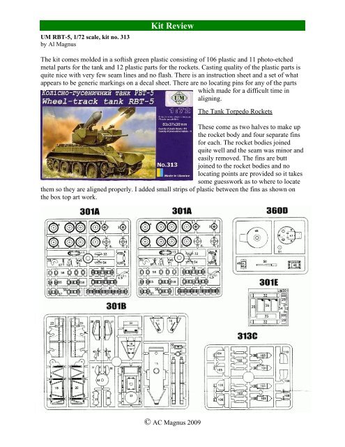
UM <strong>RBT</strong>-5, 1/<strong>72</strong> <strong>scale</strong>, kit no. 313<br />
by Al Magnus<br />
Kit Review<br />
The kit comes molded in a softish green plastic consisting of 106 plastic <strong>and</strong> 11 photo-etched<br />
metal parts for the tank <strong>and</strong> 12 plastic parts for the rockets. Casting quality of the plastic parts is<br />
quite nice with very few seam lines <strong>and</strong> no flash. There is an instruction sheet <strong>and</strong> a set of what<br />
appears to be generic markings on a decal sheet. There are no locating pins for any of the parts<br />
which made for a difficult time in<br />
aligning.<br />
The Tank Torpedo <strong>Rockets</strong><br />
These come as two halves to make up<br />
the rocket body <strong>and</strong> four separate fins<br />
for each. The rocket bodies joined<br />
quite well <strong>and</strong> the seam was minor <strong>and</strong><br />
easily removed. The fins are butt<br />
joined to the rocket bodies <strong>and</strong> no<br />
locating points are provided so it takes<br />
some guesswork as to where to locate<br />
them so they are aligned properly. I added small strips of plastic between the fins as shown on<br />
the box top art work.<br />
© AC Magnus 2009
The BT-5 tank<br />
Fit was acceptable for the majority but I still had to fiddle with some areas to get a good fit. For<br />
example the meeting point where the parts for the sides, bottom <strong>and</strong> glacis plate (part 18B) all<br />
meet needed some s<strong>and</strong>ing <strong>and</strong> scraping to get a good fit. Since I use methylene chloride (MEC)<br />
for gluing I was able to hold the pieces in place with my fingers as they dried since the joins<br />
were dry within seconds.<br />
The two sidewalls are made up of two pieces each (parts 91B & 21B, <strong>and</strong> 20B & 22B). There is<br />
supposed to be a small edge for the hull top to slot into but this was not the case <strong>and</strong> I had to cut<br />
approximately 1mm off the edge to allow the top hull part (part 53B) to fit between the two side<br />
pieces <strong>and</strong> lay flush. This lack of a slot did not become evident until after I had glued the two<br />
sides to the hull bottom (part 15B) so I had to do my cut very carefully after the fact with my<br />
razor saw.<br />
Tracks are of the link <strong>and</strong> length variety. I constructed my tracks in two runs per side – a top run<br />
<strong>and</strong> a bottom run. The track pieces were a bit delicate <strong>and</strong> I did manage to break one of them<br />
during construction.<br />
Step 9 of the instructions shows the construction sequence for the track links. Each of the links<br />
has a three or four notch end, with the three notch pieces slotting into the four notch pieces. I test<br />
fit the runs I planned on building before actually gluing them together. I found that the<br />
instructions were slightly off in their sequence. The long bottom run should have the 3 notch end<br />
facing to the front of the tank. The instructions show a four notch end <strong>and</strong> if you follow the<br />
progression of notched ends around the wheels, if you have the four notch end facing forward<br />
you will get a four notch to four notch join which doesn’t work.<br />
I also found that I needed one less link for the track links that wrap around the idler wheel at the<br />
front.<br />
The fenders were to close to the idler wheel at the front of the tank <strong>and</strong> prevented the track<br />
pieces from going between them. I was forced to remove the fenders which I had already glued<br />
in place. The resultant s<strong>and</strong>ing to remove the scars in the plastic also removed the majority of the<br />
bolt detail.<br />
Another oddity was the turret. The bottom (part 46D) has a small circular disc surrounding the<br />
locating peg for the turret <strong>and</strong> hull. This disc doesn’t fit into the tiny hole <strong>and</strong> leaves the turret sit<br />
a bit proud of the hull, leaving a small gap between the hull <strong>and</strong> the turret that allows light<br />
through. I found this rather odd <strong>and</strong> opened up the hole in the hull so that the turret fit flush to<br />
the hull. Why UM did this I have no idea but it just makes for another niggly item that has to be<br />
done to make this kit look better.<br />
Photo-etched parts are nicely done. It was quite easy to bend the engine cover to shape but I<br />
found that it came up a bit short <strong>and</strong> didn’t quite meet the top of the deck so I had to add plastic<br />
shims to close the gap. I replaced the rear tow loops with replacements made from wire because<br />
the photo-etched tow loops are extremely fragile <strong>and</strong> a bit on the thin side in my opinion.<br />
I left the tracks off during painting. After painting the road wheels <strong>and</strong> idler were super glued to<br />
the kit. To make things easier I did not glue the drive sprockets to the tank. Then the tracks were<br />
© AC Magnus 2009
added, first with the bottom run <strong>and</strong> then with the top run. While adding the tracks I left the drive<br />
sprocket loose to allow me to adjust the runs marginally before I glued the tracks to the wheels.<br />
Once the runs were in place I set the drive sprockets by adding super glue to the back side where<br />
the wheel went onto its shaft.<br />
I performed a few basic modifications. I added braces between the fins of the TT Tank<br />
Torpedoes as shown on the box top art work. I drilled out holes in the mantlet <strong>and</strong> the main gun<br />
barrel. The small opening for the periscope, which was molded to the turret top (part 51D), was<br />
drilled out as well.<br />
The mantlet is designed to allow the gun to traverse up <strong>and</strong> down. This requires the modeller to<br />
drill out holes to accept small pegs cast into the side of the mantlet (part 48D). I didn’t bother<br />
with this <strong>and</strong> trimmed off the pegs <strong>and</strong> glued the mantlet in place.<br />
I also replaced the grab h<strong>and</strong>le in front of the driver’s position with one made from bent wire.<br />
No pioneer tools (shovel, pick axe etc.) are included, though I’m not sure how often they were<br />
carried so their absence may not be an issue per se.<br />
The last item was a section of chain between the front tow hooks.<br />
The rockets were painted an overall Testors Flat Black. The tank was painted with Testors<br />
Russian Armour Green <strong>and</strong> weathered.<br />
All in all this was an interesting build, though at times it was quite frustrating with fit problems<br />
encountered with the hull <strong>and</strong> fender pieces.<br />
© AC Magnus 2009


