2012 Chevrolet Police Technical Manual (pdf) - GM Fleet
2012 Chevrolet Police Technical Manual (pdf) - GM Fleet
2012 Chevrolet Police Technical Manual (pdf) - GM Fleet

Create successful ePaper yourself
Turn your PDF publications into a flip-book with our unique Google optimized e-Paper software.
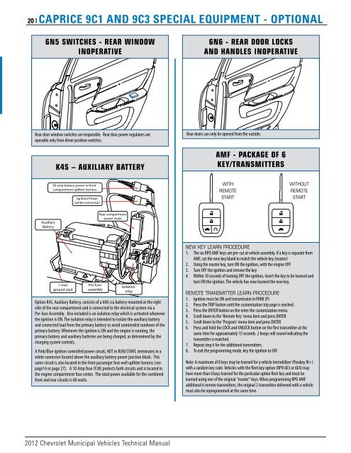
20 | caPrIcE 9c1 aND 9c3 sPEcIaL EquIPmENt - oPtIoNaL<br />
6N5 SwITcHES - REAR wINDOw<br />
INOPERATIVE<br />
Rear door window switches are inoperable. Rear door power regulators are<br />
operable only from driver position switches.<br />
Auxiliary<br />
Battery<br />
k4S – AUXILIARY BATTERY<br />
50 amp battery power to front<br />
compartment up�tter harness<br />
8 mm<br />
ground stud<br />
Ignition Power<br />
(white connector)<br />
Pre-fuse<br />
assembly<br />
Rear compartment<br />
power studs<br />
Isolation<br />
relay<br />
Option K4S, Auxiliary Battery, consists of a 600 cca battery mounted at the right<br />
side of the rear compartment and is connected to the electrical system via a<br />
Pre-fuse Assembly. Also included is an isolation relay which is activated whenever<br />
the ignition is ON. The isolation relay is intended to isolate the auxiliary battery<br />
and connected load from the primary battery to avoid unintended rundown of the<br />
primary battery. Whenever the ignition is ON and the engine is running, the<br />
primary battery and auxiliary batteries are being charged, as determined by the<br />
charging system controls.<br />
A Pink/Blue ignition controlled power circuit, HOT in RUN/START, terminates in a<br />
white connector located above the auxiliary battery power junction block. This<br />
same circuit is also located in the front passenger foot well upfitter harness (see<br />
page14 or page 27). A 10 Amp fuse (F38) protects both circuits and is located in<br />
the engine compartment fuse center. The total power available for the combined<br />
front and rear circuits is 60 watts.<br />
<strong>2012</strong> <strong>Chevrolet</strong> Municipal Vehicles <strong>Technical</strong> <strong>Manual</strong><br />
6N6 - REAR DOOR LOckS<br />
AND HANDLES INOPERATIVE<br />
Rear doors can only be opened from the outside.<br />
AMF - PAckAGE OF 6<br />
kEY/TRANSMITTERS<br />
With<br />
REMotE<br />
StaRt<br />
Without<br />
REMotE<br />
StaRt<br />
nEW kEy LEaRn PRoCEDuRE<br />
1. The six RPO AMF keys are pre-cut at vehicle assembly. If a key is separate from<br />
AMF, cut the new key blank to match the vehicle key (master)<br />
2. Using the master key, turn ON the ignition, with the engine OFF<br />
3. Turn OFF the ignition and remove the key<br />
4. Within 10 seconds of turning OFF the ignition, insert the key to be learned and<br />
turn ON the ignition. The vehicle has now learned the new key.<br />
REMotE tRanSMittER LEaRn PRoCEDuRE<br />
1. Ignition must be ON and transmission in PARK (P)<br />
2. Press the TRIP button until the customization trip page is reached.<br />
3. Press the ENTER button on the enter the customization menu.<br />
4. Scroll down to the 'Remote Key' menu item and press ENTER<br />
5. Scroll down to the 'Program' menu item and press ENTER<br />
6. Press and hold the LOCK and UNLOCK button on the first transmitter at the<br />
same time for approximately 15 seconds. 2 beeps will sound indicating the<br />
transmitter is matched.<br />
7. Repeat step 6 for the additional transmitters.<br />
8. To exit the programming mode, key the ignition to OFF.<br />
Note: A maximum of 8 keys may be learned for a vehicle immobilizer (Passkey III+)<br />
with a random key code. Vehicles with the fleet key option (RPO 6E3 or 6E4) may<br />
have more than 8 keys learned for the particular option fleet key and must be<br />
learned using one of the original "master" keys. When programming RPO AMF<br />
additional 6 remote transmitters, the original 2 transmitter delivered with a vehicle<br />
must also be reprogrammed at the same time.