Piled Foundation Design and Construction - Gnpgeo.com.my
Piled Foundation Design and Construction - Gnpgeo.com.my
Piled Foundation Design and Construction - Gnpgeo.com.my

Create successful ePaper yourself
Turn your PDF publications into a flip-book with our unique Google optimized e-Paper software.
PILED FOUNDATION<br />
DESIGN & CONSTRUCTION<br />
By Ir. Dr. Gue See Sew<br />
http://www.gnpgeo.<strong>com</strong>.<strong>my</strong>
Contents<br />
• Overview<br />
• Preliminary Study<br />
• Site Visit & SI Planning<br />
• Pile <strong>Design</strong><br />
• Pile Installation Methods<br />
• Types of Piles
Contents (Cont’d)<br />
• Piling Supervision<br />
• Pile Damage<br />
• Piling Problems<br />
• Typical <strong>Design</strong> <strong>and</strong> <strong>Construction</strong> Issues<br />
• Myths in Piling<br />
• Case Histories<br />
• Conclusions
Overview
What is a Pile <strong>Foundation</strong><br />
It is a foundation system that<br />
transfers loads to a deeper<br />
<strong>and</strong> <strong>com</strong>petent soil layer.
When To Use Pile <strong>Foundation</strong>s<br />
• Inadequate Bearing Capacity of Shallow<br />
<strong>Foundation</strong>s<br />
• To Prevent Uplift Forces<br />
• To Reduce Excessive Settlement
PILE CLASSIFICATION<br />
• Friction Pile<br />
– Load Bearing Resistance derived mainly<br />
from skin friction<br />
• End Bearing Pile<br />
– Load Bearing Resistance derived mainly<br />
from base
Overburden Soil Layer<br />
Friction Pile
End Bearing Pile<br />
Overburden Soil<br />
Rock / Hard Layer
Preliminary Study
Preliminary Study<br />
• Type & Requirements of Superstructure<br />
• Proposed Platform Level (ie CUT or FILL)<br />
• Geology of Area<br />
• Previous Data or Case Histories<br />
• Subsurface Investigation Planning<br />
• Selection of Types & Size of Piles
Previous Data & Case<br />
Histories<br />
Existing<br />
Development<br />
A<br />
Proposed<br />
Development<br />
Existing<br />
Development<br />
B<br />
Only Need Minimal<br />
Number of Boreholes<br />
Bedrock<br />
Profile
Challenge The Norm Thru<br />
Innovation To Excel
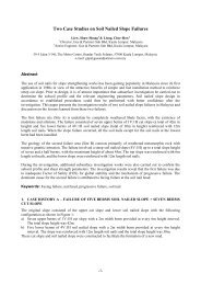
SELECTION OF PILES<br />
Factors Influencing Pile Selection<br />
– Types of Piles Available in Market (see Fig. 1)<br />
– Installation Method<br />
– Contractual Requirements<br />
– Ground Conditions (eg Limestone, etc)<br />
– Site Conditions & Constraints (eg Accessibility)<br />
– Type <strong>and</strong> Magnitude of Loading<br />
– Development Program & Cost<br />
– etc
TYPE OF PILES<br />
DISPLACEMENT PILES<br />
NON-DISPLACEMENT PILES<br />
TOTALLY PREFORMED PILES<br />
(A ready-made pile is driven or jacked<br />
into the ground)<br />
DRIVEN CAST IN-PLACE PILES<br />
(a tube is driven into ground to<br />
form void)<br />
Bored piles<br />
Micro piles<br />
Hollow<br />
Small displacement<br />
Solid<br />
Concrete Tube<br />
Steel Tube<br />
Steel Pipe<br />
Concrete Spun Piles<br />
Closed ended<br />
tube concreted<br />
with tube left in<br />
position<br />
Closed ended tube<br />
Open ended tube<br />
extracted while<br />
concreting (Franki)<br />
Concrete<br />
Steel H-piles<br />
(small displacement)<br />
Bakau piles<br />
Treated timber pile<br />
Precast R.C.<br />
piles<br />
Precast prestressed<br />
piles<br />
FIG 1: CLASSIFICATION OF PILES
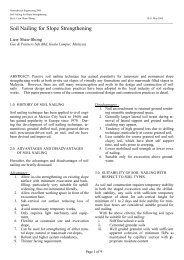
PREFORMED PILES<br />
LEGEND :<br />
GEOTECHNICAL<br />
SCALE OF LOAD<br />
(STRUCTURAL)<br />
BEARING TYPE<br />
TYPE OF<br />
BEARING<br />
LAYER<br />
GROUND<br />
WATER<br />
UNIT COST<br />
TYPE OF INTERMEDIATE LAYER<br />
ENVIRONME<br />
NT<br />
DESIGN<br />
CONSIDERATIONS<br />
TYPE OF PILE<br />
BAKAU PILES<br />
10000 x x a a a a x a x<br />
70%)<br />
x x a a a a <br />
DENSE / VERY DENSE SAND<br />
x a a a a a a a a a<br />
SOFT SPT < 4<br />
a a a a a a a a a a<br />
COHESIVE SOIL<br />
M. STIFF SPT = 4 - 15 a a a a a a a a a a a<br />
V. STIFF SPT = 15 - 32 a a a a a a a a a a<br />
HARD SPT > 32<br />
x a a a a a a a a a<br />
LOOSE SPT < 10<br />
a a a a a a a a a a a<br />
COHESIVELESS SOIL<br />
M. DENSE SPT = 10 - 30 a a a a a a a a a a<br />
DENSE SPT = 30 - 50 x a a a a a a a a a<br />
V. DENSE SPT > 50 x x a a a a a a a <br />
S < 100 mm x a a a a a a a a <br />
SOIL WITH SOME BOULDERS / 100-1000mm x x a a a a x<br />
COBBLES (S=SIZE)<br />
1000-3000mm x x a x<br />
>3000mm x x a x<br />
ABOVE PILE CAP<br />
a a a a a a a a a a a<br />
BELOW PILE CAP<br />
x a a a a a a a a a a<br />
NOISE + VIBRATION; COUNTER MEASURES<br />
REQUIRED<br />
a a a a a a<br />
PREVENTION OF EFFECTS ON ADJOINING<br />
STRUCTURES<br />
a a a<br />
(SUPPLY & INSTALL) RM/TON/M 0.5-2.5 0.3-2.0<br />
1.0-3.5 1-2 0.5-2 1.5-3 1-2.5<br />
TIMPER PILES<br />
RC PILES<br />
PSC PILES<br />
SPUN PILES<br />
STEEL H PILES<br />
STEEL PIPE PILES<br />
JACKED PILES<br />
BORED PILES<br />
MICROPILES<br />
AUGERED PILES<br />
8<br />
x<br />
<br />
INDICATES THAT THE PILE TYPE IS<br />
SUITABLE<br />
INDICATES THAT THE PILE TYPE IS<br />
NOT SUITABLE<br />
INDICATES THAT THE USE OF PILE<br />
TYPE IS DOUBTFUL OR NOT COST<br />
EFFECTIVE UNLESS ADDITIONAL<br />
MEASURES TAKEN<br />
FIG 2 : PILE SELECTION CHART
Pile Selection Based on Cost<br />
Details:<br />
250mm Spun Piles<br />
300mm Spun Piles<br />
Micropile<br />
Total Points<br />
83<br />
70<br />
70<br />
Average Length<br />
9m<br />
9m<br />
9m<br />
Average Rock Socket Length<br />
-<br />
-<br />
2.5m<br />
Indicative Rates :<br />
Mob & Demob<br />
RM 50,000.00<br />
RM 50,000.00<br />
RM 20,000.00<br />
Supply<br />
RM 33.00 / m<br />
RM 42.00 / m<br />
-<br />
Drive<br />
RM 30.00 / m<br />
RM 32.00 / m<br />
-<br />
Cut Excess, Dispose + Starter Bars<br />
RM 200.00 / Nos<br />
RM 200.00 / Nos<br />
-<br />
Movement<br />
-<br />
-<br />
RM 200.00 / Nos<br />
Drilling in Soil<br />
-<br />
-<br />
RM 110.00 / m<br />
Drilling in Rock<br />
-<br />
-<br />
RM 240.00 / m<br />
API Pipe<br />
-<br />
-<br />
RM 120.00 / m<br />
Grouting<br />
-<br />
-<br />
RM 85.00 / m<br />
Pile Head<br />
-<br />
-<br />
RM 150.00 / Nos<br />
Est. Ave. Cost Per Point<br />
RM 967.00 / Nos<br />
RM 1,066.00 / Nos<br />
RM 4,297.50 / Nos<br />
Est. <strong>Foundation</strong> Cost<br />
RM 190,261.00<br />
RM 184,620.00<br />
RM 380,825.00<br />
√
Site Visit <strong>and</strong> SI Planning
Site Visit<br />
Things To Look For …<br />
• Accessibility & Constraints of Site<br />
• Adjacent Structures/Slopes, Rivers,<br />
Boulders, etc<br />
• Adjacent Activities (eg excavation)<br />
• Confirm Topography & Site Conditions<br />
• Any Other Observations that may affect<br />
<strong>Design</strong> <strong>and</strong> <strong>Construction</strong> of <strong>Foundation</strong>
Subsurface Investigation (SI)<br />
Planning<br />
• Provide Sufficient Boreholes to get Subsoil Profile<br />
• Collect Rock Samples for Strength Tests (eg UCT)<br />
• In-Situ Tests to get consistency of ground (eg SPT)<br />
• Classification Tests to Determine Soil Type<br />
Profile<br />
• Soil Strength Tests (eg CIU)<br />
• Chemical Tests (eg Chlorine, Sulphate, etc)
Typical Cross-Section at Hill Site<br />
Hard Material Level<br />
Ground Level<br />
Very Hard Material Level<br />
Bedrock Level<br />
Groundwater Level
CROSS SECTION<br />
BH<br />
EXISTING<br />
GROUND<br />
LEVEL<br />
BH<br />
C’ 1<br />
, ø’ 1<br />
BH<br />
Perched WT<br />
Clayey Layer<br />
C’ 2<br />
, ø’ 2<br />
Seepage<br />
C’ 3<br />
, ø’ 3<br />
Water Table
Placing Boreholes in Limestone<br />
Areas<br />
• Stage 1 : Preliminary S.I.<br />
- Carry out geophysical survey (for large areas)<br />
• Stage 2: Detailed S.I.<br />
- Boreholes at Critical Areas Interpreted from<br />
Stage 1<br />
• Stage 3: During <strong>Construction</strong><br />
- Rock Probing at Selected Columns to<br />
supplement Stage 2
Pile <strong>Design</strong>
PILE DESIGN<br />
Allowable Pile Capacity is the minimum of :<br />
1) Allowable Structural Capacity<br />
2) Allowable Geotechnical Capacity<br />
a. Negative Skin Friction<br />
b. Settlement Control
PILE DESIGN<br />
Structural consideration<br />
• Not overstressed during h<strong>and</strong>ling, installation & in<br />
service for pile body, pile head, joint & shoe.<br />
• Dimension & alignment tolerances (<strong>com</strong>mon<br />
defects)<br />
• Compute the allowable load in soft soil (
Pile Capacity <strong>Design</strong><br />
Structural Capacity<br />
• Concrete Pile<br />
Q all = 0.25 x f cu x A c<br />
• Steel Pile<br />
Q all = 0.3 x f y x A s<br />
Q all<br />
= Allowable pile<br />
capacity<br />
f cu<br />
= characteristic strength<br />
of concrete<br />
f s<br />
= yield strength of steel<br />
A c<br />
= cross sectional area of<br />
concrete<br />
A s<br />
= cross sectional area of<br />
steel<br />
• Prestressed Concrete Pile<br />
Q all = 0.25 (f(<br />
cu – Prestress after loss) x A c
Pile Capacity <strong>Design</strong><br />
Geotechnical Capacity<br />
Collection of SI Data<br />
Depth (m)<br />
0<br />
2<br />
4<br />
6<br />
8<br />
10<br />
12<br />
14<br />
16<br />
18<br />
Depth Vs SPT-N Blow Count<br />
0 50 100 150 200 250 300 350 400<br />
Upper Bound<br />
0<br />
2<br />
4<br />
6<br />
8<br />
20<br />
22<br />
24<br />
Lower<br />
Bound<br />
<strong>Design</strong> Line<br />
(Moderately<br />
Conservative)<br />
10<br />
26<br />
0 50 100 150 200 250 300 350<br />
SPT Blow Count per 300mm Penetration<br />
400<br />
12
Pile Capacity <strong>Design</strong><br />
Geotechnical Capacity<br />
Collection of SI Data<br />
Depth Vs SPT-N Blow Count<br />
Depth Vs SPT-N Blow Count<br />
0 50 100 150 200 250 300 350 400<br />
0 50 100 150 200 250 300 350 400<br />
0<br />
0<br />
0<br />
0<br />
2<br />
2<br />
4<br />
2<br />
4<br />
2<br />
6<br />
6<br />
Depth (m)<br />
8<br />
10<br />
12<br />
14<br />
Upper Bound<br />
4<br />
6<br />
Depth (m)<br />
8<br />
10<br />
12<br />
14<br />
4<br />
6<br />
16<br />
16<br />
18<br />
20<br />
22<br />
24<br />
Lower<br />
Bound<br />
<strong>Design</strong> Line<br />
8<br />
10<br />
18<br />
20<br />
22<br />
24<br />
Lower<br />
Bound<br />
<strong>Design</strong> Line<br />
Upper Bound<br />
8<br />
10<br />
26<br />
12<br />
26<br />
12<br />
0 50 100 150 200 250 300 350 400<br />
SPT Blow Count per 300mm Penetration<br />
0 50 100 150 200 250 300 350 400<br />
SPT Blow Count per 300mm Penetration
Pile Capacity <strong>Design</strong><br />
Geotechnical Capacity<br />
• Piles installed in a group may fail:<br />
• Individually<br />
• As a block
Pile Capacity <strong>Design</strong><br />
Geotechnical Capacity<br />
• Piles fail individually<br />
• When installed at large spacing
Pile Capacity <strong>Design</strong><br />
Geotechnical Capacity<br />
• Piles fail as a block<br />
• When installed at close spacing
Pile Capacity <strong>Design</strong><br />
Single Pile Capacity
Pile Capacity <strong>Design</strong><br />
Factor of Safety (FOS)<br />
Factor of Safety (FOS) is required<br />
for<br />
•Natural variations in soil strength &<br />
<strong>com</strong>pressibility
Pile Capacity <strong>Design</strong><br />
Factor of Safety (FOS)<br />
Factor of Safety is<br />
(FOS) required for<br />
• Different degree of<br />
mobilisation for shaft<br />
& for tip<br />
Load<br />
q smob<br />
q bmob<br />
≈ 5mm<br />
Settlement
Pile Capacity <strong>Design</strong><br />
Factor of Safety (FOS)<br />
Partial factors of safety for shaft & base<br />
capacities respectively<br />
• For shaft, use 1.5 (typical)<br />
• For base, use 3.0 (typical)<br />
• Q<br />
ΣQ su + Q bu<br />
all =<br />
1.5 3.0
Pile Capacity <strong>Design</strong><br />
Factor of Safety (FOS)<br />
Global factor of safety for total ultimate<br />
capacity<br />
• Use 2.0 (typical)<br />
• Q all =<br />
ΣQ su + Q bu<br />
2.0
Pile Capacity <strong>Design</strong><br />
Factor of Safety (FOS)<br />
• Calculate using BOTH approaches<br />
(Partial & Global)<br />
• Choose the lower of the Q all values
Pile Capacity <strong>Design</strong><br />
Single Pile Capacity<br />
Q u = Q s + Q b<br />
Q u<br />
= ultimate bearing capacity<br />
Q s<br />
= skin friction<br />
Q b<br />
= end bearing<br />
Overburden Soil Layer
Pile Capacity <strong>Design</strong><br />
Single Pile Capacity : In Cohesive Soil<br />
Q su<br />
Q bu<br />
Q u = α.s us .A s + s ub .N c .A b<br />
Q u = Ultimate bearing capacity of the pile<br />
a = adhesion factor (see next slide)<br />
s us = average undrained shear strength for shaft<br />
A s = surface area of shaft<br />
s ub = undrained shear strength at pile base<br />
N c = bearing capacity factor (taken as 9.0)<br />
A b = cross sectional area of pile base
Pile Capacity <strong>Design</strong><br />
Single Pile Capacity: In Cohesive Soil<br />
Adhesion factor (α)(<br />
– Shear strength (S u )<br />
(McClell<strong>and</strong>, 1974)<br />
1.0<br />
0.8<br />
Preferred<br />
<strong>Design</strong> Line<br />
0.6<br />
C α<br />
/S u<br />
0.4<br />
Adhesion<br />
Factor<br />
0.2<br />
0<br />
25 50 75 100 125 150 175<br />
Su (kN/m 2 )
Meyerhof<br />
Fukuoka<br />
SPT N<br />
f su =2.5N<br />
(kPa)<br />
s u =<br />
(0.1+0.15N)*50<br />
(kPa)<br />
α<br />
f su =α.s u<br />
(kPa)<br />
0<br />
0<br />
5<br />
1<br />
5<br />
1<br />
2.5<br />
12.5<br />
1<br />
12.5<br />
5<br />
12.5<br />
42.5<br />
0.7<br />
29.75<br />
10<br />
25<br />
80<br />
0.52<br />
41.6<br />
15<br />
37.5<br />
117.5<br />
0.4<br />
47<br />
20<br />
50<br />
155<br />
0.33<br />
51.15<br />
30<br />
75<br />
230<br />
0.3<br />
69<br />
40<br />
100<br />
305<br />
0.3<br />
91.5
Pile Capacity <strong>Design</strong><br />
Single Pile Capacity: In Cohesive Soil<br />
Correlation Between SPT N <strong>and</strong> f su<br />
f su vs SPT N<br />
110<br />
100<br />
90<br />
80<br />
70<br />
fsu<br />
(kPa)<br />
60<br />
50<br />
40<br />
30<br />
20<br />
10<br />
0<br />
0 5 10 15 20 25 30 35 40 45<br />
SPT N<br />
Meyerhof<br />
Fukuoka
Pile Capacity <strong>Design</strong><br />
Single Pile Capacity: In Cohesive Soil<br />
• Values of undrained shear strength, s u can be<br />
obtained from the following:<br />
Unconfined <strong>com</strong>pressive test<br />
Field vane shear test<br />
Deduce based on Fukuoka’s Plot (minimum s u )<br />
Deduce from SPT-N values based on Meyerhof<br />
NOTE: Use only direct field data for shaft friction prediction<br />
instead of Meyerhof
Pile Capacity <strong>Design</strong><br />
Single Pile Capacity: In Cohesive Soil<br />
Modified Meyerhof (1976):<br />
Ult. Shaft friction = Q su<br />
≅ 2.5N (kPa)<br />
Ult. Toe capacity = Q bu ≅ 250N (kPa)<br />
or 9 s u (kPa)<br />
(Beware of base cleaning for bored piles –<br />
ignore base capacity if doubtful)
Pile Capacity <strong>Design</strong><br />
Single Pile Capacity: In Cohesionless Soil<br />
Modified Meyerhof (1976):<br />
• Ult. . Shaft Friction = Q su ≅ 2.0N (kPa(<br />
kPa)<br />
• Ult. . Toe Capacity= Q bu ≅ 250N – 400N<br />
(kPa)
Pile Capacity <strong>Design</strong><br />
Load (kN)<br />
0 100 200 300 400 500<br />
0<br />
0<br />
4<br />
4<br />
ΣQ su<br />
Depth (m)<br />
8<br />
12<br />
ΣQ su + Q bu<br />
1.5 3.0<br />
16<br />
Q bu<br />
ΣQ su + Q bu<br />
ΣQ su + Q bu<br />
2.0<br />
8<br />
12<br />
16<br />
20<br />
0 200 400 600<br />
20
Pile Capacity <strong>Design</strong><br />
Block Capacity
Pile Capacity <strong>Design</strong><br />
Block Capacity:In Cohesive Soil<br />
Q u = 2D(B+L) s + 1.3(s b .N c .B.L)<br />
Where<br />
Q u = ultimate bearing capacity of pile group<br />
D = depth of pile below pile cap level<br />
B = width of pile group<br />
L = length of pile group<br />
s = average cohesion of clay around group<br />
s b = cohesion of clay beneath group<br />
N c = bearing capacity factor = 9.0<br />
(Refer to Text by Tomlinson, 1995)
Pile Capacity <strong>Design</strong><br />
Block Capacity: In Cohesionless Soil<br />
No risk of group failure<br />
if FOS of individual pile is<br />
adequate
Pile Capacity <strong>Design</strong><br />
Block Capacity: On Rock<br />
No risk of block failure<br />
if the piles are properly<br />
seated in the rock<br />
formation
Pile Capacity <strong>Design</strong><br />
Negative Skin Friction (NSF)
Pile Capacity <strong>Design</strong><br />
Negative Skin Friction<br />
• Compressible soil layer consolidates<br />
with time due to:<br />
‣ Surcharge of fill<br />
‣ Lowering of groundwater table
Pile Capacity <strong>Design</strong><br />
Negative Skin Friction<br />
OGL<br />
Fill<br />
H f<br />
ρ s<br />
0<br />
1 2 3Month<br />
Clay
Pile Capacity <strong>Design</strong><br />
Negative Skin Friction<br />
Pile to length (floating pile)<br />
‣ Pile settles with consolidating soil <br />
NO NSF
Pile Capacity <strong>Design</strong><br />
Negative Skin Friction<br />
Pile to set at hard stratum (endbearing<br />
pile)<br />
‣ Consolidation causes downdrag forces on<br />
piles as soil settles more than the pile
Pile Capacity <strong>Design</strong><br />
Negative Skin Friction<br />
WARNING:<br />
‣ No free fill by the contractor to avoid<br />
NSF
Effect of NSF …<br />
Reduction of Pile Carrying Capacity
Effect of NSF …
NSF Preventive Measures<br />
• Avoid Filling<br />
• Carry Out Surcharging<br />
• Sleeve the Pile Shaft<br />
• Slip Coating<br />
• Reserve Structural Capacity for NSF<br />
• Allow for Larger Settlements
Pile Capacity <strong>Design</strong><br />
Negative Skin Friction<br />
Q all = (Q su /1.5 + Q bu /3.0)<br />
Q all = (Q su /1.5 + Q bu /3.0) - Q neg<br />
OGL<br />
S<strong>and</strong><br />
FL<br />
OGL<br />
Clay<br />
Q su<br />
Clay<br />
Q neg<br />
S<strong>and</strong><br />
S<strong>and</strong><br />
Q su<br />
Q ba<br />
Q ba
0<br />
Pile Capacity <strong>Design</strong><br />
Negative Skin Friction<br />
Increased Pile Axial Load<br />
Check: maximum axial load < structural pile<br />
SPT-N (Blows/300mm)<br />
Settlement (mm)<br />
0 10 20 30 40 50<br />
capacity<br />
70 60 50 40 30 20 10 0<br />
Axial Compression Force (kN)<br />
100 0 -100 -200 -300-400-500-600 -700 -800 -900-1000<br />
5<br />
10<br />
Depth (m, bgl)<br />
15<br />
20<br />
25<br />
30<br />
35<br />
40<br />
Borehole<br />
BH-1<br />
BH-2<br />
Settlement Curves &<br />
Axial Compression Force<br />
14 May 98<br />
15 May 98<br />
18 May 98<br />
21 May 98<br />
04 Jun 98<br />
09 Jun 98<br />
19 Jun 98<br />
02 Jul 98<br />
13 Jul 98<br />
Datum = 36.300m<br />
Maximum<br />
axial load
Pile Capacity <strong>Design</strong><br />
Factor of Safety (FOS)<br />
Without Negative Skin Friction:<br />
Allowable working load<br />
Q ult<br />
FOS<br />
With Negative Skin Friction:<br />
Allowable working load<br />
Q ult<br />
FOS<br />
(Q neg + etc)
Pile Capacity <strong>Design</strong><br />
Static Pile Load Test (Piles with NSF)<br />
• Specified Working Load (SWL) = Specified foundation<br />
load at pile head<br />
• <strong>Design</strong> Verification Load (DVL) = SWL + 2 Q neg<br />
• Proof Load: will not normally exceed<br />
DVL + SWL
Pile Settlement <strong>Design</strong>
Pile Settlement <strong>Design</strong><br />
In Cohesive Soil<br />
<strong>Design</strong> for total settlement &<br />
differential settlement for design<br />
tolerance<br />
In certain cases, total settlement not an<br />
issue<br />
Differential settlement can cause<br />
damage to structures
Pile Settlement <strong>Design</strong><br />
In Cohesive Soil<br />
Pile Group Settlement in Clay<br />
=<br />
Immediate /<br />
Elastic Settlement<br />
+<br />
Consolidation<br />
Settlement
IMMEDIATE SETTLEMENT<br />
μ μ0q<br />
p = 1<br />
i<br />
E<br />
Where<br />
p i = average immediate settlement<br />
q n= pressure at base of equivalent raft<br />
B = width of the equivalent raft<br />
E u = deformation modulus<br />
Pile Settlement <strong>Design</strong><br />
In Cohesive Soil<br />
u<br />
n<br />
B<br />
μ 1, μ 0 = influence factors for pile group width, B at depth D<br />
below ground surface<br />
by Janbu, Bjerrum <strong>and</strong><br />
Kjaernsli (1956)
IMMEDIATE SETTLEMENT<br />
Pile Settlement <strong>Design</strong><br />
In Cohesive Soil<br />
μ 1<br />
μ 0<br />
Influence factors (after<br />
Janbu, Bjerrum <strong>and</strong><br />
Kjaernsli, 1956)
Pile Settlement <strong>Design</strong><br />
In Cohesive Soil<br />
CONSOLIDATION SETTLEMENT<br />
As per footing (references given later)
Pile Settlement <strong>Design</strong><br />
On Rock<br />
No risk of excessive<br />
settlement
Pile Installation Methods
PILE INSTALLATION<br />
METHODS<br />
•Diesel / Hydraulic / Drop Hammer<br />
Driving<br />
•Jacked-In<br />
•Prebore Then Drive<br />
•Prebore Then Jacked In<br />
•Cast-In-Situ Pile
Diesel Drop Hammer<br />
Driving<br />
Hydraulic Hammer<br />
Driving
Jacked-In<br />
Piling
Jacked-In Piling (Cont’d)
Cast-In-Situ<br />
Piles<br />
(Micropiles)
Types of Piles
TYPES OF PILES<br />
•Treated Timber<br />
Piles<br />
•Bakau Piles<br />
•R.C. Square Piles<br />
•Pre-Stressed<br />
Concrete Spun<br />
Piles<br />
•Steel Piles<br />
•Boredpiles<br />
•Micropiles<br />
•Caisson Piles
R.C. Square Piles<br />
•Size : 150mm to 400mm<br />
•Lengths : 3m, 6m, 9m <strong>and</strong> 12m<br />
•Structural Capacity : 25Ton to 185Ton<br />
•Material : Grade 40MPa Concrete<br />
•Joints: Welded<br />
•Installation Method :<br />
–Drop Hammer<br />
–Jack-In
RC<br />
Square<br />
Piles
Pile Marking
Pile Lifting
Pile Fitting to Piling Machine
Pile<br />
Positioning
Pile Joining
Considerations in Using RC<br />
Square Piles …<br />
•Pile Quality<br />
•Pile H<strong>and</strong>ling Stresses<br />
•Driving Stresses<br />
•Tensile Stresses<br />
•Lateral Loads<br />
•Jointing
Pre-stressed Concrete Spun<br />
Piles<br />
•Size : 250mm to 1000mm<br />
•Lengths : 6m, 9m <strong>and</strong> 12m (Typical)<br />
•Structural Capacity : 45Ton to 520Ton<br />
•Material : Grade 60MPa & 80MPa Concrete<br />
•Joints: Welded<br />
•Installation Method :<br />
–Drop Hammer<br />
–Jack-In
Spun Piles
Spun Piles vs RC Square Piles<br />
Spun Piles have …<br />
•Better Bending Resistance<br />
•Higher Axial Capacity<br />
•Better Manufacturing Quality<br />
•Able to Sustain Higher Driving Stresses<br />
•Higher Tensile Capacity<br />
•Easier to Check Integrity of Pile<br />
•Similar cost as RC Square Piles
Steel H Piles<br />
•Size : 200mm to 400m<br />
•Lengths : 6m <strong>and</strong> 12m<br />
•Structural Capacity : 40Ton to 1,000Ton<br />
•Material : 250N/mm 2 to 410N/mm 2 Steel<br />
•Joints: Welded<br />
•Installation Method :<br />
–Hydraulic Hammer<br />
–Jack-In
Steel H<br />
Piles
Steel H Piles (Cont’d)
Steel H Piles Notes…<br />
•Corrosion Rate<br />
•Fatigue<br />
•OverDriving
OverDriving<br />
of Steel Piles
Large Diameter Cast-In<br />
In-Situ<br />
Piles (Bored Piles)<br />
• Size : 450mm to 2m<br />
• Lengths : Varies<br />
• Structural Capacity : 80Ton to 2,300Tons<br />
• Concrete Grade : 20MPa to 30MPa (Tremie)<br />
• Joints : None<br />
• Installation Method : Drill then Cast-In-Situ
Drilling<br />
Borepile <strong>Construction</strong><br />
Overburden Soil Layer<br />
Bedrock
Advance Drilling<br />
Borepile <strong>Construction</strong><br />
Overburden Soil Layer<br />
Bedrock
Drilling & Advance<br />
Casing<br />
Borepile <strong>Construction</strong><br />
Overburden Soil Layer<br />
Bedrock
Drill to Bedrock<br />
Borepile <strong>Construction</strong><br />
Overburden Soil Layer<br />
Bedrock
Lower<br />
Reinforcement<br />
Cage<br />
Borepile <strong>Construction</strong><br />
Overburden Soil Layer<br />
Bedrock
Lower Tremie<br />
Chute<br />
Borepile <strong>Construction</strong><br />
Overburden Soil Layer<br />
Bedrock
Pour Tremie<br />
Concrete<br />
Borepile <strong>Construction</strong><br />
Overburden Soil Layer<br />
Bedrock
Completed<br />
Borepile<br />
Borepile <strong>Construction</strong><br />
Overburden Soil Layer<br />
Bedrock
BORED PILING MACHINE<br />
Bored Pile <strong>Construction</strong><br />
BG22
Cleaning Bucket<br />
Rock Reamer<br />
Rock Auger
Rock Chisel<br />
Harden Steel
DRILLING EQUIPMENT<br />
Bored Pile <strong>Construction</strong><br />
Cleaning<br />
bucket<br />
Coring<br />
bucket<br />
Soil auger
Bored Pile <strong>Construction</strong><br />
BENTONITE PLANT<br />
Des<strong>and</strong>ing<br />
Machine<br />
Water<br />
Tank<br />
Mixer<br />
Slurry<br />
Tank
Drilling
Lower<br />
Reinforcement
Place<br />
Tremie<br />
Concrete
Completed Boredpile
Borepile Cosiderations…<br />
•Borepile Base Difficult to Clean<br />
•Bulging / Necking<br />
•Collapse of Sidewall<br />
•Dispute on Level of Weathered Rock
Micropiles<br />
•Size : 100mm to 350mm Diameter<br />
•Lengths : Varies<br />
•Structural Capacity : 20Ton to 250Ton<br />
•Material : Grade 25MPa to 35MPa Grout<br />
•Joints: None<br />
•Installation Method :<br />
N80 API Pipe as Reinforcement<br />
–Drill then Cast-In-Situ<br />
–Percussion Then Cast-In-Situ
Cast-In<br />
In-Situ<br />
Piles<br />
(Micropiles)
TYPES OF PILE SHOES<br />
•Flat Ended Shoe<br />
•Oslo Point<br />
•Cast-Iron Pointed Tip<br />
•Cross Fin Shoe<br />
•H-Section
Cross Fin Shoe
Oslo Point Shoe
Cast Iron Tip Shoe
H-Section Shoe
Piling Supervision
Uniform Building By<br />
Law (UBBL)1984
PILING SUPERVISION<br />
•Ensure That Piles Are Stacked Properly<br />
•Ensure that Piles are Vertical During Driving<br />
•Keep Proper Piling Records<br />
•Ensure Correct Pile Types <strong>and</strong> Sizes are Used<br />
•Ensure that Pile Joints are Properly Welded with<br />
NO GAPS<br />
•Ensure Use of Correct Hammer Weights <strong>and</strong> Drop<br />
Heights
PILING SUPERVISION<br />
(Cont’d)<br />
•Ensure that Proper Types of Pile Shoes are Used.<br />
•Check Pile Quality<br />
•Ensure that the Piles are Driven to the Required<br />
Lengths<br />
•Monitor Pile Driving
FAILURE OF PILING<br />
SUPERVISION<br />
Failing to Provide Proper Supervision<br />
WILL Result in<br />
Higher Instances of Pile Damage<br />
& Wastage
Pile Damage
Driven concrete piles are vulnerable<br />
to damages by overdriving.
Damage to Timber Pile
Weak<br />
Timber<br />
Joint
Damage To RC Pile Toe
Damage to<br />
RC Pile<br />
Head
Damage to<br />
RC Piles
Damage to RC Piles – cont’d
Tilted RC<br />
Piles
Damage to Steel Piles
Damaged Steel Pipe Piles
Detection of Pile Damage<br />
Through Piling Records
Piling Problems
Piling Problems – Soft Ground
Piling Problems – Soft Ground<br />
Ground heave due to<br />
pressure relief at base &<br />
surcharge near<br />
excavation<br />
Pile tilts & moves/walks
Piling Problems – Soft Ground
Piling in Kuala Lumpur Limestone<br />
Important Points to Note:<br />
• Highly Irregular Bedrock Profile<br />
• Presence of Cavities & Solution Channels<br />
• Very Soft Soil Immediately Above Limestone<br />
Bedrock<br />
Results in …<br />
• High Rates of Pile Damage<br />
• High Bending Stresses
Piling Problems in Typical Limestone<br />
Bedrock
Piling Problems – Undetected<br />
Problems
Piling Problems – Coastal Alluvium
Piling Problems – Defective Piles<br />
Seriously damaged<br />
pile due to severe<br />
driving stress in soft<br />
ground (tension)<br />
Defect due to poor<br />
workmanship of pile<br />
casting
Piling Problems – Defective Piles<br />
Defective pile shoe<br />
Problems of<br />
defective pile head<br />
& overdriving!
Piling Problems – Defective Piles<br />
Nonchamfered<br />
corners<br />
Cracks&<br />
fractured
Piling Problems – Defective Piles<br />
Pile head defect due to<br />
hard driving or <strong>and</strong> poor<br />
workmanship
Piling Problem - Micropiles<br />
Sinkholes caused by<br />
installation methoddewatering
Piling in Fill Ground<br />
Important Points to Note:<br />
•High Consolidation Settlements If Original Ground is<br />
Soft<br />
•Uneven Settlement Due to Uneven Fill Thickness<br />
•Collapse Settlement of Fill Layer If Not Compacted<br />
Properly<br />
Results in …<br />
•Negative Skin Friction (NSF) & Crushing of Pile Due<br />
to High Compressive Stresses<br />
•Uneven Settlements
Typical <strong>Design</strong> <strong>and</strong><br />
<strong>Construction</strong> Issues #1<br />
Issue #1<br />
Pile Toe Slippage Due to Steep Incline Bedrock<br />
Solution #1<br />
Use Oslo Point Shoe To Minimize Pile Damage
Pile Breakage on Inclined<br />
Rock Surface<br />
No Proper Pile<br />
Shoe
Pile<br />
Joint<br />
Extension Pile
First Contact<br />
B/W Toe <strong>and</strong><br />
Inclined Rock
Pile Joint Breaks<br />
Pile Body Bends<br />
Toe “Kicked Off”<br />
on Driving
Pile Breakage on Inclined<br />
Rock Surface<br />
Continue<br />
“Sliding” of<br />
Toe
Use Oslo Point Shoe to Minimize<br />
Damage
<strong>Design</strong> <strong>and</strong> <strong>Construction</strong><br />
Issues #2<br />
Issue #2<br />
Presence of Cavity<br />
Solution #2<br />
Detect Cavities through Cavity Probing then<br />
perform Compaction Grouting
Presence of Cavity<br />
Pile Sitting on<br />
Limestone<br />
with Cavity
Application of<br />
Building Load
Application of<br />
Building Load<br />
Roof of Cavity<br />
starts to Crack …
Building Collapse<br />
Pile Plunges !<br />
Collapse of<br />
Cavity Roof
<strong>Design</strong> <strong>and</strong> <strong>Construction</strong><br />
Issues #3<br />
Issue #3<br />
Differential Settlement<br />
Solution #3<br />
Carry out analyses to check the settlement<br />
<strong>com</strong>patibility if different piling system is adopted
Differential Settlement of <strong>Foundation</strong><br />
Link<br />
SAFETY<br />
House<br />
of<br />
<strong>Construction</strong><br />
Original Building<br />
Not Compromised<br />
Soft<br />
Layer<br />
Original House<br />
on Piles<br />
Piling in Progress<br />
No Settlement<br />
Piles<br />
transfer<br />
Load to<br />
Hard<br />
Layer<br />
No<br />
pile<br />
Cracks!!<br />
Renovation:<br />
Construct<br />
Extensions<br />
Settlement<br />
Hard Layer<br />
SPT>50
Eliminate Differential Settlement<br />
Construct<br />
Extension with<br />
Suitable Piles<br />
Piling in Progress<br />
Soft<br />
Layer<br />
All Load transferred to Hard<br />
Layer – No Cracks!<br />
Hard Layer<br />
SPT>50
Problem of Short Piles<br />
Cracks!!<br />
Piling in Progress<br />
Construct<br />
Extensions<br />
with Short<br />
Piles<br />
Soft<br />
Layer<br />
Soft!<br />
Load<br />
transferred to<br />
Soft Layer,<br />
Extension<br />
still Settles<br />
Load from Original House<br />
transferred to Hard Layer<br />
Hard Layer<br />
SPT>50
Cracks at Extension
Typical <strong>Design</strong> <strong>and</strong><br />
<strong>Construction</strong> Issues #4<br />
Issue #4<br />
Costly conventional piling design – piled to set to<br />
deep layer in soft ground<br />
Solution #4<br />
-Strip footings / Raft<br />
-Floating Piles
“Conventional” <strong>Foundation</strong> for<br />
Low Rise Buildings
<strong>Foundation</strong> for<br />
Low Rise Buildings (Soil Settlement)
Settling Platform Detached from Building<br />
Settlement<br />
Exposed Pile
Conceptual <strong>Design</strong> of<br />
FOUNDATION SYSTEM<br />
1. Low Rise Buildings :-<br />
(Double-Storey Houses)<br />
= Strip Footings or Raft or<br />
Combination.<br />
2. Medium Rise Buildings :-<br />
= Floating Piles System.
Low Rise Buildings on<br />
<strong>Piled</strong> Raft/Strips<br />
Fill<br />
25-30m<br />
Soft Clay<br />
Strip / Raft<br />
System<br />
Stiff<br />
Stratum<br />
Hard Layer
Comparison<br />
Building on Piles<br />
Building on <strong>Piled</strong> Strips<br />
Fill<br />
25-30m<br />
Soft Clay<br />
Strip<br />
System<br />
Stiff<br />
Stratum<br />
Hard Layer
Comparison (after settlement)<br />
Building on Piles<br />
Building on <strong>Piled</strong> Strips<br />
Fill<br />
25-30m<br />
Soft Clay<br />
Strip<br />
System<br />
Stiff<br />
Stratum<br />
Hard Layer
Advantages of<br />
Floating Piles System<br />
1. Cost Effective.<br />
2. No Downdrag problems on the<br />
Piles.<br />
3. Insignificant Differential<br />
Settlement between Buildings <strong>and</strong><br />
Platform.
B<strong>and</strong>ar Botanic
B<strong>and</strong>ar Botanic at Night
Soft Ground Engineering
Myths in Piling
MYTHS IN PILING #1<br />
Myth:<br />
Dynamic Formulae such as Hiley’s Formula<br />
Tells us the Capacity of the Pile<br />
Truth:<br />
Pile Capacity can only be verified by using:<br />
(i) Maintained (Static) Load Tests<br />
(ii)Pile Dynamic Analyser (PDA) Tests
MYTHS IN PILING #2<br />
Myth:<br />
Pile Achieves Capacity When It is Set.<br />
Truth:<br />
Pile May Only “Set” on Intermediate Hard<br />
Layer BUT May Still Not Achieve Required<br />
Capacity within Allowable Settlement.
CASE HISTORIES<br />
• Case 1: Structural distortion & distresses<br />
• Case 2: Distresses at houses
CASE HISTORY 1<br />
Distortion & Distresses on 40<br />
Single/ 70 Double Storey Houses<br />
• Max. 20m Bouldery Fill on<br />
Undulating Terrain<br />
• Platform Settlement<br />
• Short Piling Problems<br />
• Downdrag on Piles
Distresses on Structures
Void
Reduced Level (m )<br />
70<br />
60<br />
50<br />
40<br />
30<br />
20<br />
Offset 36.2m<br />
Offset 13.1m<br />
N=30<br />
N=5<br />
N=25 <br />
N=29 <br />
<br />
Profile with SPT 'N'>50<br />
<br />
<br />
<br />
Piling Contractor A<br />
Offset 13.1m<br />
N=40<br />
Profile with SPT 'N'≅30<br />
<br />
<br />
<br />
Offset 13.1m<br />
<br />
N=34<br />
Original<br />
Ground Profile<br />
Filled ground<br />
Original Ground<br />
Hard Stratum<br />
Borehole<br />
Pile Toe<br />
Pile Toe of Additional<br />
Piles<br />
Building<br />
Platform<br />
0 40000 80000 120000 160000 200000<br />
Coordinate-X (mm)
80<br />
Piling<br />
Contractor A<br />
Piling Contractor B<br />
R e d uced Level (m )<br />
70<br />
60<br />
50<br />
40<br />
30<br />
N=30<br />
N=5<br />
N=29<br />
<br />
Offset 9.1m<br />
Profile with SPT 'N'≅30<br />
<br />
<br />
<br />
N=34<br />
N=28<br />
N=41<br />
Profile with SPT 'N'>50<br />
Offset 9.1m<br />
Original Ground Profile<br />
Building Platform<br />
Filled ground<br />
Original Ground<br />
Hard Stratum<br />
Borehole<br />
Pile Toe<br />
Pile Toe of Additional<br />
Piles<br />
0 40000 80000 120000 160000 200000<br />
Coordinate-X (mm)
Prevention Measures<br />
• <strong>Design</strong>:<br />
– Consider downdrag in foundation design<br />
– Alternative strip system<br />
• <strong>Construction</strong>:<br />
– Proper QA/QC<br />
– Supervision
CASE HISTORY 2<br />
Distresses on 12 Double Storey<br />
Houses & 42 Townhouses<br />
• Filled ground: platform settlement<br />
• <strong>Design</strong> problem: non-suspended floor<br />
with semi-suspended detailing<br />
• Bad earthwork & layout design<br />
• Short piling problem
Diagonal cracks due<br />
to differential<br />
settlement between<br />
columns<br />
Larger column<br />
settlement
Sagging<br />
Ground<br />
Floor Slab
SAGGING PROFILE OF NON-<br />
SUSPENDED GROUND FLOOR SLAB<br />
NON-SUSPENDED GROUND FLOOR<br />
SLAB BEFORE SETTLEMENT<br />
V e > V c<br />
ρ s<br />
V c<br />
V c < V e<br />
PILE<br />
PILECAP<br />
BUILDING PLATFORM PROFILE AFTER<br />
SETTLEMENT<br />
ρ s<br />
ACTUAL FILLED PLATFORM SETTLEMENT
Distorted Car Porch Roof
Poor Earthwork Layout<br />
Silt trap<br />
BLOCK 2<br />
BLOCK 1<br />
Temporary<br />
earth drain
Prevention Measures<br />
• Planning:<br />
– Proper building layout planning to suit terrain<br />
(eg. uniform fill thickness)<br />
– Sufficient SI<br />
• <strong>Design</strong>:<br />
– Consider filled platform settlement<br />
– Earthwork layout<br />
• <strong>Construction</strong>:<br />
– Supervision on earthwork & piling
SUMMARY<br />
• Importance of Preliminary Study<br />
• Underst<strong>and</strong>ing the Site Geology<br />
• Carry out Proper Subsurface Investigation<br />
that Suits the Terrain & Subsoil<br />
• Selection of Suitable Pile<br />
• Pile <strong>Design</strong> Concepts
SUMMARY<br />
• Importance of Piling Supervision<br />
• Typical Piling Problems Encountered<br />
• Present Some Case Histories
FERRARI ‘S PITSTOP WAS COMPLETED BY<br />
15 MECHANICS (FUEL AND TYRES) IN 6.0<br />
SECONDS FLAT.<br />
54 PEOPLE TOOK PART IN THIS<br />
CONCERTED ACROBATIC JUMP.