Download PDF - Voith Turbo
Download PDF - Voith Turbo
Download PDF - Voith Turbo

Create successful ePaper yourself
Turn your PDF publications into a flip-book with our unique Google optimized e-Paper software.
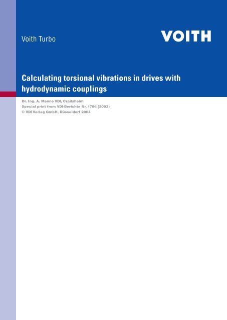
Calculating torsional vibrations in drives with<br />
hydrodynamic couplings<br />
Dr. Ing. A. Menne VDI, Crailsheim<br />
Special print from VDI-Berichte Nr. 1786 (2003)<br />
© VDI Verlag GmbH, Düsseldorf 2004
1. Introduction<br />
In order to ensure high reliability and safety for a drive system,<br />
it is essential that resonance ranges and component loads are<br />
calculated in advance. This is achieved by simulation calculations<br />
which are carried out with more or less drastically simplified<br />
versions of the actual systems behaviour. In this case, the<br />
simplified systems behaviour is represented by mathematical<br />
models. Such models exist for many drive line elements which<br />
mostly originate from physical basics, for example Hooke’s<br />
law.<br />
Hydrodynamic couplings, however, are highly complex in their<br />
operation. Modelling across larger operating areas is therefore<br />
a very challenging task [1, 2, 3]. But in most cases, it is sufficient<br />
to limit the mathematical description to one operating<br />
range, the nominal operating point. Under these conditions, a<br />
rather simple description of hydrodynamic couplings was developed<br />
in the form of a Kelvin model [4], which can be easily<br />
determined and also reproduced with any standard simulation<br />
software program.<br />
The validity of this Kelvin model is to be proven once more in<br />
this paper, as well as the fundamental characteristics of hydrodynamic<br />
couplings derived from it. Moreover, two basic practical<br />
problems for the design and simulation of drives with hydrodynamic<br />
couplings, especially marine drives, are explained.<br />
• Simulation calculations in resonant ranges (second mode or<br />
higher) repeatedly show wide fluctuations between theory<br />
(simulation) and actual measurements, so that there are<br />
insecurities regarding the validity of coupling models in this<br />
area.<br />
• In the past it was standard procedure that drives with hydrodynamic<br />
couplings were designed separately. Primary and<br />
secondary driveline were regarded independently, eigenfrequencies<br />
and torsional loads were determined separately.<br />
Over the years, doubts were, however, raised, whether<br />
hydrodynamic couplings might not have a much stronger<br />
influence on the eigenfrequencies and the torsional loads<br />
of primary and secondary drivelines after all, which would<br />
mean that separate designs could lead to major failures. For<br />
this reason, such systems are now no longer separated but<br />
designed as complete units.<br />
2. Hydrodynamic coupling as Kelvin model<br />
A stationary design of a hydrodynamic couplings is carried out<br />
y<br />
as described in<br />
g<br />
Equ. 1.<br />
5<br />
D P<br />
T = λ ⋅ ρ ⋅ ⋅ ω<br />
Equ. 1<br />
2<br />
P<br />
The non-dimensional performance figure λ is in this case<br />
dependent on slip, the profile parameters and the degree of<br />
filling, and is obtained by experiment. It flows, like the density<br />
of the operating medium ρ, linearly into the calculation of the<br />
transmittable coupling torque.<br />
With geometrically similar couplings, the course of the performance<br />
figure λ does not change, so that this torque, with the<br />
diameter of the pump impeller D P<br />
and the pump speed ω can<br />
also be theoretically determined for other models and input<br />
speeds.<br />
However, non-stationary procedures cannot be calculated with<br />
Equ. 1. For this, a different description is required, which has<br />
been developed in [4] in the form of a Kelvin model.<br />
T P<br />
ϕ P<br />
Θ P Θ T<br />
Fig 1: Kelvin Model (Indices: P = Pump; T = Turbine)<br />
As is generally known, this model consists of a parallel arrangement<br />
of a Hooke spring K and a viscous damper D (Fig. 1) and<br />
is analogue to the description of highly flexible couplings [5].<br />
For this coupling type, the spring capacity and the damping<br />
value are assumed as constant values.<br />
Oil filling<br />
Turbine wheel<br />
Pump wheel<br />
Fig. 2: Cross section of VTC 487 T coupling<br />
D<br />
K<br />
The hydrodynamic coupling, however, distinguishes itself by<br />
non-linear behaviour even at nominal operating point, which<br />
results in frequency-dependent values for K and D. These are<br />
exemplarily illustrated for coupling size VTC 487 T (Fig. 2) at a<br />
pump speed of 1500 rpm and a nominal torque of 800 Nm in<br />
Fig. 3 and Fig. 4. At low excitation frequencies, the stiffness is<br />
low and the damping effect high. With increasing frequency,<br />
this effect reverses. In both cases, stiffness and damping effect<br />
are striving against a boundary value. Compared to other drive<br />
elements, the boundary value of the stiffness is very low. In<br />
this case, its value is at 3500 Nm/rad and corresponds, for example,<br />
to that of a steel shaft with a diameter of 30 mm and a<br />
length of 1863 mm. In a drive system, the stiffness of the other<br />
drive elements is at least one power of ten higher than that of<br />
the hydrodynamic coupling. Even highly flexible couplings are<br />
higher by a factor >3 at an identical nominal torque. This leads<br />
to the conclusion that the initial eigenfrequency of a drive is<br />
determined by the hydrodynamic coupling.<br />
ϕ T<br />
T T<br />
∅ 90<br />
∅ Pump = DP = 487 mm
K (Nm / rad)<br />
4000<br />
3000<br />
2000<br />
1000<br />
0<br />
0 5 10 15 20 25 30 35 40 45 50<br />
Fig. 3: Stiffness K<br />
D (Nm s / rad)<br />
Fig. 4: Damping D<br />
Outside the nominal slip area (from 0% to approx. 10%), the<br />
model according to [4] loses its validity and can therefore not<br />
be used for calculations of start-up and run-out procedures.<br />
Here, other modelling approaches need to be chosen [1, 2, 3],<br />
some of which are, however, highly complex. In most cases, it<br />
is sufficient to calculate start-up and run-out procedures such<br />
as these, which are often quasi-stationary, with the stationary<br />
characteristic curve of the coupling.<br />
3. Characteristics of hydrodynamic couplings<br />
3.1 Low-pass behaviour<br />
From the stiffness K and the damping effect D, the transmission<br />
behaviour of hydrodynamic couplings can be deduced in<br />
the form of an enlargement factor V. It is defined as the quotient<br />
of coupling T K<br />
to exciter torque T E<br />
(Equ. 2) [5].<br />
with<br />
and<br />
•<br />
T K<br />
= D ⋅ ∆ ϕ + K ⋅ ∆ϕ<br />
T E<br />
T P<br />
Θ<br />
Θ + Θ<br />
In Fig. 5, such a function is illustrated for coupling type VTC<br />
487 T that has already been looked at. In this example, the<br />
eigenfrequency has been pre-set with 5 Hz and is meant to<br />
correspond with the first mode of the entire drive system. Due<br />
to the very low stiffness and the mass distribution in the drive<br />
system, this mode is determined by the hydrodynamic coupling.<br />
V (dB)<br />
160<br />
120<br />
80<br />
40<br />
Fig. 5: Enlargement function<br />
P<br />
T<br />
Exciter frequency (Hz)<br />
0<br />
0 5 10 15 20 25 30 35 40 45 50<br />
10<br />
0<br />
-10<br />
-20<br />
-30<br />
Exciter frequency (Hz)<br />
T<br />
V =<br />
T<br />
T<br />
= ⋅<br />
or<br />
K<br />
E<br />
ΘP<br />
T E<br />
= T T<br />
⋅<br />
Θ + Θ<br />
P<br />
Equ. 2<br />
-40<br />
0,01 0,1 1 10<br />
Exciter frequency/Eigenfrequency<br />
T<br />
From Fig. 5, a low-pass behaviour with a low rise in resonance<br />
can be deduced. Up to the first eigenfrequency, the exciter torques<br />
are transmitted by the hydrodynamic coupling, but they<br />
are strongly damped. However, the coupling torque T K<br />
decreases<br />
rapidly with increasing frequency. At six times the eigenfrequency<br />
(30 Hz) it is a mere -30,5 dB (V = 3%) of the exciter<br />
torque T E<br />
. This means that there is a wide-reaching decoupling<br />
and/or separation of torque fluctuations. The resonance rise is<br />
uncritical, because, at +4,2 dB (V = 160%), it is in this case very<br />
low.<br />
Of particular interest is the height of the maximum first eigenfrequency<br />
(first mode). Owing to the low stiffness of all standard<br />
coupling types, sizes and systems, it is
a well-known fact that the eigenfrequency changes with the<br />
square root from the stiffness (Equ. 5), it is also proportional to<br />
the input speed (Equ. 6).<br />
The most influential parameters on the torsional vibration behaviour<br />
of hydrodynamic couplings are the coupling size and<br />
the coupling design, the filling level, the operating medium<br />
used, as well as the input speed, the nominal operating point<br />
and the exciter frequency.<br />
In view of such a high number of influential parameters, a model<br />
verification can only be carried out selectively. A complete<br />
experimental investigation would be immensely costly and<br />
labor-intensive. The coupling behaviour therefore needs to be<br />
extrapolated to other conditions.<br />
With the description per [4] and the above–mentioned influential<br />
parameters, the two parameters ‘stiffness’ and ‘damping’<br />
of the Kelvin model can be relatively easily determined, so that<br />
this extrapolation can be carried out without problems. In this<br />
way, the influence of individual parameters and their effect on<br />
the drive system can also be examined.<br />
The model verifications presented here were carried out at a<br />
marine drive with a nominal output of 1800 kW and a hydrodynamic<br />
double coupling size 1150 (VTC 1150 DTM), as well as by<br />
test stand measurements at a coupling size 487 (VTC 487 T) at<br />
an output of 125 kW.<br />
2<br />
K ~ (Input speed)<br />
Equ. 4<br />
Inherent eigenfrequency ∼ √K ~ K<br />
Equ. 5<br />
Inherent eigenfrequency ∼ Input ~ Input speed speed<br />
Equ. 6<br />
The frequency ratio Ω in Equ. 3 is constant in most drive<br />
systems, for example the exciter spectrum of a combustion<br />
en gine, a propeller or the rotor of a wind power station. Here,<br />
the exciter frequencies are always in proportion to the input<br />
speed, and the frequency ratio Ω is hence constant. Normally,<br />
torsional eigenfrequencies are not a function of speed, but<br />
constant. (Fig. 7). The fact that they can still take on this role, is<br />
not alarming, but rather advantageous. As can be easily seen,<br />
no further intersections of the exciters with this eigenfrequency<br />
alignment exist above this input speed (except at 0 rpm).<br />
A system as described in Fig. 7 is therefore in the overcritical<br />
range at any drive speed. But even a scenario, where the first<br />
eigenfrequency is close to an exciter line, can be quite permissible.<br />
This is to be illustrated later by the example of a marine<br />
drive.<br />
4.1 Model verification on the basis of test<br />
stand measurements<br />
∆Τ<br />
The torque amplitudes in Fig. 6 were obtained in test stand<br />
measurements at a VTC 487 T coupling. As described above,<br />
an operating point of 790 Nm (slip = 3.3%) was set at a pump<br />
speed of 1500 rpm, and the pump side was harmonically<br />
excited with increasing frequency and torque amplitude. In<br />
Fig. 8 the measured speed amplitudes are illustrated.<br />
∆n (rpm) ∆Τ<br />
50<br />
40<br />
30<br />
20<br />
10<br />
0<br />
0 5 10 15 20 25 30 35 40 45 50<br />
Exciter frequency (Hz)<br />
Fig. 8: Measuring values – speed amplitudes of pump side<br />
(red) and turbine side (blue)<br />
eigenfrequency<br />
Inh. 2nd Exciter frequency<br />
.<br />
2nd eigenfrequency<br />
Inherent 1st Exciter frequency<br />
1st Exciter frequency<br />
From the four measured variables in Fig. 6 und Fig. 8, the stiffness<br />
and damping values for the individual exciter frequencies<br />
can be determined with the phase information not shown here.<br />
This is shown in Fig. 9 und Fig. 10, and, for direct comparison,<br />
also the theoretically determined values per [4]. The conformity<br />
is very good and is hence another confirmation of the theory<br />
of coupling modelling.<br />
∆<br />
4000<br />
.<br />
Fig. 7: Example of a resonance graph<br />
Input speed n<br />
K (Nm / rad)<br />
3000<br />
2000<br />
1000<br />
0<br />
0 2 4 6 8 10 12 14 16 18 20 22<br />
Exciter frequency (Hz)<br />
4. Verification of Kelvin models for<br />
hydrodynamic couplings<br />
Fig. 9: Stiffness K – Measurements (dots); theory (continued)<br />
D (Nm s / rad)<br />
160<br />
120<br />
80<br />
40<br />
0<br />
0 2 4 6 8 10 12 14 16 18 20 22<br />
Exciter frequency (Hz)<br />
Fig. 10: Damping D – Measurements (dots); Theory (continued)<br />
An experimental determination of the stiffness and damping<br />
values at an exciter frequency above 20 Hz is very difficult, because<br />
the difference angles and speeds, from which the Kelvin<br />
parameters are determined, are declining with increasing frequency.<br />
Inaccuracies in the measuring value recordings would<br />
have a strong influence on the result, so that such measurements<br />
were omitted.<br />
η<br />
On the other hand, model verifications for exciter frequencies<br />
above 20 Hz are not strictly necessary. As mentioned earlier,<br />
the first eigenfrequency of a drive system is determined by the
hydrodynamic coupling and is at < 20 Hz for most standard<br />
coupling designs, sizes and systems, sometimes even below<br />
10 Hz. Higher eigenfrequencies occur in the primary and secondary<br />
drive line and are hardly influenced by the hydrodynamic<br />
coupling. This subject will be referred to in greater detail<br />
at a later stage of this paper. Verifying the coupling model for<br />
exciter frequencies above 20 Hz would therefore be irrelevant<br />
Auxiliary drives with<br />
gear stages<br />
Highly flexible coupling<br />
4.2 Model verification at a marine drive<br />
The marine drive shown in Fig. 11 originates from the water<br />
tractor “M.V. Taurus“. This boat is equipped with two eight-cylinder<br />
diesel engines rated at 1812 kW, both of which drive a<br />
<strong>Voith</strong> Schneider Propeller through a hydrodynamic <strong>Voith</strong> coupling.<br />
Contrary to the test stand measurements, it is in this case<br />
not possible to generate targeted individual exciter frequencies<br />
and hence determine stiffness and damping. The examination<br />
of the coupling model is carried out by means of the calculated<br />
and measured eigenfrequencies.<br />
Torque measurements were carried out by strain gauge at the<br />
connect ing shaft of the gear coupling. At this point, the first<br />
and the third eigenfrequency could be determined, both of<br />
which are in the secondary-side system. Owing to the low-pass<br />
behaviour of the hydrodynamic coupling, primary-side located<br />
modes could not be measured.<br />
In the marine drive in Fig. 11, the main excitation occurs<br />
through the propeller, i. e. primarily at 5 and 10 times the propeller<br />
speed (number of blades = 5). Under consideration of<br />
the gear stage, the first propeller exciter frequency equals the<br />
0.39 th order of the input speed, i. e. it is proportional to it.<br />
Exciter frequency propeller = 0.39 order of engine speed<br />
The requirements of Equ. 3 are therefore fulfilled. The calculation<br />
[4] shows that the first eigenfrequency of the drive is equal<br />
to the 0.37 th order of the engine speed.<br />
Calculated fi rst eigenfrequency= 0.37 order of engine speed<br />
Exciter frequency and eigenfrequency are therefore close to<br />
each other. In the frequency spectrum, a rise occurs precisely<br />
in this area (0.37 th to 0.39 th order), which increases with the<br />
engine speed and the pitch adjustment of the propeller. Alternating<br />
torques of variable heights were measured in the<br />
connecting shaft of the gear coupling during various applications<br />
of the water tractor. In unfavourable cases, the value was<br />
+/- 3.86 kNm. German Lloyd prescribe a value of +/- 30% of the<br />
medium nominal torque in the speed range of 90% to 105% as<br />
maximum permissible alternating torque. With a maximum of<br />
+/- 22.3% of the nominal torque, we are therefore within the<br />
permissible range with this drive.<br />
As shown by this example, operation that is close to the first<br />
eigenfrequency caused by the hydrodynamic coupling, can<br />
certainly be permissible. This statement can, however, not be<br />
generalized and needs to be examined from case to case.<br />
The third eigenfrequency was determined with 31.8 Hz on the<br />
basis of the measurements and is found in the secondary-side<br />
drive system. With a frequency of 30.4 Hz, the simulation calculation<br />
is a mere 4.4% below the measuring value, which is<br />
a good result. It must be remarked here, that the stiffness of<br />
the hydrodynamic coupling has no significant influence on this<br />
eigenfrequency. The third mode to 29.8 Hz was also calcu lated<br />
without it (see following chapter 5).<br />
1<br />
2<br />
3<br />
4<br />
5<br />
6<br />
7<br />
8<br />
Damper<br />
P = 1812 kW<br />
n = 1000 rpm<br />
8 Cylinder<br />
Flywheel<br />
Hydrodynamic coupling<br />
<strong>Voith</strong> DTM1150<br />
Gear coupling<br />
Fig. 11: Mass scheme of marine drive<br />
5. Separate design of primary and<br />
secondary-side drivelines<br />
<strong>Voith</strong> Schneider<br />
Propeller<br />
A separate design of primary and secondary-side drivelines<br />
can be highly advantageous, if, at an early project stage, not<br />
all drive elements are known. In this case, the issue is not so<br />
much the stationary design, but the determination of eigenfrequencies<br />
and the question of possible resonance excitations.<br />
In the past, separate designs were carried out, for example,<br />
for marine drives. Here, it can be the case that drive motor or<br />
propeller systems are not yet known during the project phase.<br />
In order to be able to determine the relevant other, primary<br />
or secondary-side drive system, the entire system used to be<br />
hypothetically separated by the hydrodynamic coupling. An<br />
influence of the primary side on the secondary side and vice<br />
versa was hence excluded. Over the years, this method was,<br />
however, put in doubt, so that separate designs are no longer<br />
practised today. For the above reasons, this makes the work of<br />
the project engineer more difficult, so that he will always raise<br />
the question of the validity of the previous design approach.<br />
For drives with wide differences in mass and/or stiffness distribution,<br />
eigenfrequencies can also be allocated directly to<br />
individual components, such as drive shafts, highly flexible<br />
couplings or gearboxes. Drive systems with hydrodynamic<br />
couplings often show large differences when it comes to the<br />
distribution of their stiffness; in this case, the coupling stiffness<br />
is usually by at least one power of ten lower than the stiffness<br />
of the other elements.
This results in the first eigenfrequency being determined by<br />
the turbo coupling, amounting to less than 20 Hz for all standard<br />
drive systems, often even to less than 10 Hz. For the determination<br />
of the first eigenfrequency, it is therefore sufficient<br />
to reduce the entire drive system to a two-mass flywheel and<br />
calculate it with the coupling stiffness [4]. The frequency thus<br />
calculated is higher than the actual frequency. The minimum<br />
first eigenfrequency can be determined by applying Neuber’s<br />
limit value theory [6].<br />
Higher eigenfrequencies can initially be determined by treating<br />
the primary and secondary side of drivelines separately. In this<br />
case, the stiffness of the hydrodynamic coupling is neglected.<br />
Modes determined in this way coincide quite well with actual<br />
values. Table 1 shows a comparison of eigenfrequencies that<br />
have been calculated with and without coupling stiffness. The<br />
example refers to a torsional vibration chain with 6 masses<br />
and the values stated in Table 2.<br />
Table 1: Inherent frequencies calculated with and without<br />
coupling stiffness<br />
with hydrodynamic coupling without hydrodynamic coupling<br />
primary secondary primary secondary<br />
Mode 1 4,030 Hz (4,135 Hz) 1 0,000 Hz<br />
Mode 2 19,922 Hz 19,461 Hz<br />
Mode 3 73,552 Hz 73,431 Hz<br />
Mode 4 90,241 Hz 90,179 Hz<br />
Mode 5 1219,6 Hz 1219,6 Hz<br />
1 Value in brackets obtained after reduction to two-mass flywheel<br />
Separate designs must, however, be treated with some caution.<br />
It needs to be ensured that the coupling stiffness is at<br />
least one power of ten lower than that of the other drive elements.<br />
Experience has shown that deviations resulting from<br />
separate frequency determination can be assumed to amount<br />
to +/- 6%. Since the validity of the method described here is<br />
not theoretically proven and also dependant on the distribution<br />
of masses, it is always recommended to check the entire<br />
system. This applies in particular, if the “separate” calculation<br />
results in resonance-near operation.<br />
exciter frequency, in order to establish whether permissible<br />
values have been exceeded. Especially with resonances that<br />
are close to each other, the superposition of individual excitations<br />
can quickly result in a doubling of the load.<br />
6. Simulation calculations within the<br />
resonance range<br />
In theory, simulation calculations within the resonance range<br />
are indeed possible. The question here is to determine the<br />
amplitudes during excitation closely to or directly at the point<br />
of resonance. What may work well theoretically, often proves<br />
difficult in practice. There may be considerable differences<br />
between the simulated and the measured amplitudes which<br />
can amount to several 100%.<br />
The reasons for this are primarily incorrect or only partly accurate<br />
data and/or assumptions regarding the drive system or<br />
the systems excitations. Even slight deviations between the<br />
calculated and the actual eigenfrequencies, or wrong assumptions<br />
regarding the systems excitation, might be sufficient to<br />
falsify the simulation results considerably. A similar scenario<br />
occurs, if the damping values, e. g. gears, shafts and connecting<br />
elements, are inaccurate.<br />
In general, simulation calculations within the resonance range<br />
are to be carried out with utmost care and to be evaluated<br />
critically. The decisive question is here, by which component<br />
(shaft, gearbox, turbo coupling, etc.) the mode, i. e. the eigenfrequency,<br />
is primarily determined.<br />
The biggest problems occur, if a resonance is determined by<br />
a component that is only slightly damped (e. g. cardan shaft<br />
or torsionally stiff connecting coupling). Slight shifts of the<br />
as sumed exciter or the calculated eigenfrequency have a particularly<br />
noticeable effect in this instance. However, the exciter<br />
amplitude, too, has a major influence in connection with the<br />
system damping. As a guide value, simulation calculations in<br />
the +/- 20% frequency range should either be completely avoided<br />
for such a resonance point, or at least be looked at with a<br />
very critical eye.<br />
Table 2: Values of torsional vibration chain<br />
The question, whether a secondary-side eigenfrequency is<br />
excited by the primary side (or vice versa) through the hydrodynamic<br />
coupling, and how high the amplitudes are, can only<br />
be answered by the system as a whole. Systems excitations<br />
with high frequencies may be drastically reduced by a hydrodynamic<br />
coupling, but they are still transmitted. However, this<br />
usually does not result in a noticeable increase of the total<br />
load. With modes that are only slightly damped, this may,<br />
nevertheless lead to problems. In this case, higher resonance<br />
rises are possible even with low exciter amplitudes.<br />
It also needs to be observed that the total load on the system<br />
consists of the sum of all individual loads. It is therefore not<br />
sufficient to simply look at the amplitudes of each individual<br />
Fig. 12 illustrates the enlargement functions of a slightly and<br />
a strongly damped system. As can be seen, within the range<br />
+/- 20%, the function increases drastically by the eigenfrequency<br />
(dots in the diagram). For example, a frequency shift<br />
η = 0,92 to η = 0,96, i. e. 4.4%, would result in a doubling of the<br />
amplitude. This example demonstrates clearly, how sensitive<br />
calculations in this area are.<br />
Θ6 = 5 kg m 2<br />
Mass inertias Stiffness with Stiffness without<br />
hydrodynamic coupling<br />
hydrodynamic coupling<br />
Θ1 = 6 kg m 2 K12 = 5,0*10 7 Nm / rad K12 = 5,0*10 7 Nm / rad<br />
Θ2 = 1 kg m 2 K23 = 4,5*10 5 Nm / rad K23 = 4,5*10 5 Nm / rad<br />
Θ3 = 3 kg m 2 K34 = 3,0*10 3 Nm / rad K34 = 0,0 Nm / rad<br />
Θ4 = 2 kg m 2 K45 = 2,0*10 5 Nm / rad K45 = 2,0*10 5 Nm / rad<br />
Θ5 = 1 kg m 2 K56 = 3,0*10 4 Nm / rad K56 = 3,0*10 4 Nm / rad<br />
40<br />
30<br />
20<br />
10<br />
0<br />
-10<br />
-20<br />
0,1 1 10<br />
V (dB)<br />
η = Exciter frequency/Eigenfrequency<br />
Fig. 12: Enlargement function<br />
red – strongly damped (D = 0,4);<br />
blue – slightly damped (D = 0,005)<br />
On the other hand, there are fewer problems, if an eigenfrequency<br />
is determined by a strongly damped component (e.g.<br />
hydrodynamic or highly flexible coupling). With sufficient accuracy,<br />
amplitudes may even be determined directly at their
point of resonance. Inaccuracies at the assumed exciter or the<br />
calculated eigenfrequency bear hardly any effect. The same<br />
applies to variations of the exciter amplitudes.<br />
The terms “slightly” or “strongly” damped system are to be<br />
quantified on the basis of Lehr’s damping factor D. Strictly<br />
speaking, the latter has only been defined for a one-mass system.<br />
With the help of modal analysis, a transformation to several<br />
one-mass systems is possible. We are actually speaking<br />
of a modal damping measurement according to Lehr. In Table<br />
3, the experience values for D are listed. As a general rule, the<br />
following can be assumed:<br />
D > 0,1 strongly damped system<br />
D < 0,1 slightly damped system<br />
Table 3: Experience values for Lehr’s Damping Factor<br />
Transmitting component<br />
Lehr‘s Lehr’s Damping Measurement<br />
Factor<br />
and experimental examinations of a marine drive, the applicability<br />
of the Kelvin model could be verified. Based on the<br />
assumption that the stiffness of the hydrodynamic coupling<br />
is lower by a least one power of ten than the stiffness of the<br />
remaining drive elements, a separate design of primary and<br />
secondary-side drivelines is permissible. This design is, however,<br />
limited to the observation of stationary loads, as well as the<br />
determination of eigenfrequencies. The calculation of torsional<br />
loads as a result of systems excitation must always be carried<br />
out for the entire system. The same applies to the urgently recommended<br />
examination of “separately” determined modes.<br />
Simulation calculations in the resonance range or even directly<br />
at the point of resonance, are only permissible for strongly<br />
damped modes. With slightly damped eigenfrequencies, calculations<br />
in the +/-20% area around a point of resonance should<br />
either be avoided completely, or at least be looked at with a<br />
very critical eye. Errors of several 100% are possible.<br />
Steel shaft d < 100 mm 0,005<br />
Steel shaft d > 100 mm 0,01<br />
Transmission gearing P < 100 kW 0,02<br />
Transmission gearing 100 kW < P < 1000 kW 0,04<br />
Transmission gearing P > 1000 kW 0,06<br />
Highly flexible coupling up to 0,13 (at 10 Hz) 1<br />
Hydrodynamic coupling at n = 1500 rpm 0,19 (at 10 Hz) 1<br />
3,58 (at 0,5 Hz) 1<br />
1<br />
Derived 1 Derived from from relative damping with exciter frequency = inherent = eigenfrequency of of non-damped system system<br />
As these statements show, the occasionally quite considerable<br />
differences between measurements and calculations in the<br />
resonance area are not automatically to be attributed to faulty<br />
coupling modelling. It is essentially in the nature of simulations<br />
which are always carried out on the basis of assumptions<br />
and simplifications that eigenfrequencies and systems excitations<br />
can never be determined precisely. This, in combination<br />
with high systems sensitivities, can quickly lead to false<br />
results and conclusions which in most cases carry consider able<br />
consequential costs.<br />
7. Summary<br />
For the torsional vibration behaviour of hydrodynamic couplings,<br />
a simplified description in the form of a Kelvin model<br />
with frequency-dependent stiffness and damping was presented,<br />
from which two fundamental characteristics were deduced.<br />
On the one hand, there is a low-pass behaviour with low resonance<br />
rise which can be attributed to high damping by the<br />
hydrodynamic coupling. The maximum eigenfrequency, i.e.<br />
the maximum angular frequency of this low-pass behaviour,<br />
is below 20 Hz for all standard drive systems, coupling sizes<br />
and designs, often even below 10 Hz. As a result, excitations of<br />
higher frequencies at a transmission through the coupling are<br />
strongly reduced. Yet caution needs to be applied. Especially<br />
with slightly damped modes, such excitations can still lead to<br />
higher resonance rises.<br />
The second fundamental characteristic is the speed-proportional<br />
eigenfrequency of drives with hydrodynamic coup ling.<br />
The prerequisite for this is, however, a constant ratio of exciter<br />
frequency to input speed. This is the case with most drives<br />
(e. g. combustion engines, propeller or rotor of a wind power<br />
station).<br />
By means of test stand measurements, as well as theoretical<br />
8. Literature<br />
[1] Folchert, U.: Identifikation der dynamischen Eigenschaften<br />
Hydrodynamischer Kupplungen (Identification of the<br />
dynamic characteristics of hydrodynamic couplings),<br />
Mitteilung aus dem Institut für Mechanik Nr. 87 der Ruhr<br />
Universität Bochum, 1994 (Information from Institute of<br />
Mechanics, No. 87, Ruhr University, Bochum, 1994).<br />
[2] Behrens, H.: Nichtlineare Modellierung und Identifikation<br />
hydrodynamischer Kupplungen mit allgemeinen diskreten<br />
Modellansätzen (Non-linear modelling and identification<br />
of hydrodynamic couplings with general, discreet<br />
modelling approaches), Mitteilung aus dem Institut für<br />
Mechanik Nr. 107 der Ruhr Universität Bochum, 1997<br />
(Information from Institute of Mechanics, No. 107, Ruhr<br />
University, Bochum, 1997).<br />
[3] Herbertz, R.: Untersuchung des dynamischen Verhaltens<br />
von Föttinger Getrieben (Examination of the dynamic<br />
behaviour of Foettinger transmissions), Dissertation Technische<br />
Universität Hannover, 1973.<br />
[4] Worsch, H.: Drehschwingungsverhalten von hydrodynamischen<br />
Kupplungen (Torsional vibration behaviour of<br />
hydrodynamic couplings), Sonderdruck aus <strong>Voith</strong> Forschung<br />
und Konstruktion, Heft 33 (1989), Aufsatz 2<br />
Special print by <strong>Voith</strong> Research and Design, Issue 33<br />
(1989), essay 2.<br />
[5] DIN 740, Teil 2: Nachgiebige Wellenkupplungen (Flexible<br />
shaft couplings), Beuth-Verlag, Berlin, August 1986.<br />
[6] Holzweißig / Dresig, Lehrbuch der Maschinendynamik<br />
(Fundamentals of machine dynamics), Fachbuchverlag<br />
Leipzig - Köln, 1994.
<strong>Voith</strong> <strong>Turbo</strong> GmbH & Co. KG<br />
Start-up Components<br />
P.O. Box 1555<br />
74555 Crailsheim/Germany<br />
Phone +49-7951-32-409<br />
Fax +49-7951-32-480<br />
startup.components@voith.com<br />
www.startup-components.com<br />
www.voithturbo.com<br />
Cr 597e 06/2004 2.000 VDI-Druck. Technical data and illustrations subject to change.