BD6 - Egil Eng & Co AS
BD6 - Egil Eng & Co AS
BD6 - Egil Eng & Co AS

Create successful ePaper yourself
Turn your PDF publications into a flip-book with our unique Google optimized e-Paper software.
44 100/110 ED<br />
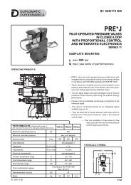
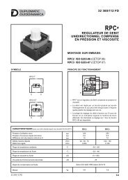
<strong>BD6</strong><br />
BANKABLE<br />
DIRECTIONAL CONTROL VALVE<br />
SERIES 20<br />
p max 280 bar<br />
Q max 40 l/min<br />
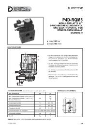
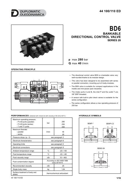
OPERATING PRINCIPLE<br />
— The directional control valve <strong>BD6</strong> is a bankable valve very<br />
well-rounded thanks to its modular design.<br />
— This valve has been designed to be assembled with series<br />
or parallel connection, mounting up to 6 body-modules.<br />
— The <strong>BD6</strong> valve is suitable for compact applications in the<br />
mobile and mini-power pack industries.<br />
— The intake ports A and B, the inlet P and the outlet T are<br />
3/8” BSP threaded.<br />
— A version with built-in pilot check valves is available for the<br />
series configuration.<br />
— The series configuration allows a max operating pressure of<br />
250 bar<br />
PERFORMANCES (obtained with mineral oil with viscosity of 36 cSt at 50°C )<br />
Maximum operating pressure:<br />
- P-A-B ports (parallel)<br />
280<br />
bar<br />
- P-A-B ports (series)<br />
250<br />
- T and T1 ports<br />
250<br />
Maximum flowrate:<br />
- parallel<br />
- series<br />
l/min 40<br />
25<br />
Pressure drops ∆p - Q see paragraph 3<br />
Electrical characteristics see paragraph 6<br />
Operating limits see paragraph 5<br />
Electrical connections see paragraph 9<br />
Ambient temperature range °C -20 / +50<br />
Fluid temperature range °C -20 / +80<br />
Fluid viscosity range cSt 10 ÷ 400<br />
According to ISO 4406:1999<br />
Fluid contamination degree<br />
class 20/18/15<br />
Recommended viscosity cSt 25<br />
Single body mass kg 1,84<br />
HYDRAULIC SYMBOLS<br />
<strong>BD6</strong>P-*<br />
<strong>BD6</strong>S-S4<br />
<strong>BD6</strong>P-C3<br />
Surface treatment of body and<br />
plates:<br />
thermochemical antioxidant<br />
44 100/110 ED 1/16
<strong>BD6</strong><br />
SERIES 20<br />
1 - IDENTIFICATION CODES FOR LOOSE MODULES<br />
Here below all the loose components identification codes of the bankable valve are shown. To order a whole assembled valve, please use the<br />
codes at paragraphes 11 and 12.<br />
The pressure control valve and the poppet type valve with unloading function are briefly described. Fore more detailed information about them<br />
please see the 21 100 datasheet for the pressure control valve and the 43 100 for the unloading valve.<br />
1.1 - Valve body<br />
BD 6 - / 20 -<br />
Bankable directional<br />
control valve<br />
Size<br />
<strong>Co</strong>nnection type:<br />
P = parallel<br />
S = series<br />
Spool type<br />
(see paragraph 1.3)<br />
Series no. (the overall and mounting<br />
dimensions remain unchanged from 20 to 29)<br />
Seals:<br />
N = NBR seals for mineral oil (standard)<br />
V = FPM seals for special fluids<br />
<strong>Co</strong>il electrical connection:<br />
(see paragraph 9)<br />
K1 = plug for connector type<br />
DIN 43650 (standard)<br />
K2 = plug for connector type<br />
AMP JUNIOR<br />
K4 = outgoing cables<br />
K7 = plug for connector type<br />
DEUTSCH DT04-2P male<br />
K8 = plug for connector type<br />
AMP SUPER SEAL<br />
<strong>Co</strong>il type<br />
D12 = 12 V<br />
D24 = 24 V direct current<br />
D28 = 28 V A<br />
R110 = 110 V<br />
rectified current<br />
R230 = 230 V @<br />
D00 = valve supplied without coils.<br />
Locking rings are supplied together with<br />
valves.<br />
NOTE: The valve bodies and plates are supplied with a thermochemical anti-oxidation treatment.<br />
1.2 - <strong>Co</strong>il identification code<br />
CD 14 - / 10<br />
Supply voltage<br />
D12 = 12 V<br />
D24 = 24 V direct current<br />
D28 = 28 V A<br />
R110 = 110 V<br />
rectified current<br />
R230 = 230 V @<br />
Series no.:<br />
(the overall and mounting dimensions remain unchanged from10 to 19)<br />
<strong>Co</strong>il electrical connection (see paragraph 6.2 for matching voltage-connections)<br />
K1 = plug for connector type DIN 43650<br />
K2 = plug for connector type AMP JUNIOR<br />
K4 = outgoing cables<br />
K7 = plug for connector type DEUTSCH DT04-2P male<br />
K8 = plug for connector type AMP SUPER SEAL<br />
44 100/110 ED 2/16
<strong>BD6</strong><br />
SERIES 20<br />
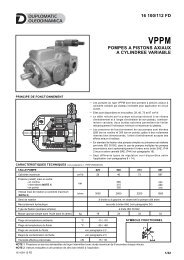
1.3 - Available spool type for parallel configuration <strong>BD6</strong>P<br />
Type S:<br />
2 solenoids - 3 positions<br />
spring centering<br />
Type SA*: 1 solenoid side A<br />
2 positions (central + external)<br />
spring centering<br />
Type SB*: 1 solenoid side B<br />
2 positions (central + external)<br />
spring centering<br />
Type RK:<br />
2 solenoids - 2 positions<br />
with mechanical retention<br />
Type TA*:<br />
1 solenoid side A<br />
2 external positions<br />
with return spring<br />
Type TB*:<br />
1 solenoid side B<br />
2 external positions<br />
with return spring<br />
Type C3: 2 solenoids 3 positions<br />
with spring centering and check valve on<br />
A and B<br />
piloting ratio: 3:1<br />
check valve cracking<br />
pressure: 3 bar<br />
Q max 40 l/min<br />
1.4 - Available spool type for series configuration <strong>BD6</strong>S<br />
Type S4:<br />
2 solenoids 3 positions<br />
spring centering<br />
Type SA*:<br />
1 solenoid side A<br />
2 positions (central + external)<br />
spring centering<br />
Type SB*:<br />
1 solenoid side B<br />
2 positions (central + external)<br />
spring centering<br />
44 100/110 ED 3/16
<strong>BD6</strong><br />
SERIES 20<br />
1.4 - Inlet module with pressure control valve for parallel connection<br />
BD 6 P - F / 20<br />
Bankable directional<br />
control valve<br />
Nominal size<br />
Parallel connections<br />
Inlet module with pressure control valve<br />
Seals:<br />
N = NBR seals for mineral oil (standard)<br />
V = FPM seals for special fluids<br />
Series no.: (the overall and mounting dimensions<br />
remain unchanged from 20 to 29)<br />
Pressure adjustment range:<br />
140 = up to 140 bar<br />
210 = up to 210 bar<br />
280 = up to 280 bar<br />
1.5 - Inlet module with pressure control valve and unloading for parallel connections<br />
BD 6 P - FK / 20 -<br />
Bankable directional<br />
control valve<br />
Nominal size<br />
Parallel connections<br />
Inlet module with pressure control<br />
valve and unloading<br />
Pressure adjustment range:<br />
140 = up to 140 bar<br />
210 = up to 210 bar<br />
280 = up to 280 bar<br />
Series no.: (the overall and mounting<br />
dimensions remain unchanged from 20 to 29)<br />
Seals:<br />
N = NBR seals for mineral oil (standard)<br />
V = FPM seals for special fluids<br />
<strong>Co</strong>il electrical connection:<br />
(see paragraph 8)<br />
K1 = plug for connector type<br />
DIN 43650 (standard)<br />
K2 = plug for connector type<br />
AMP JUNIOR<br />
K4 = outgoing cables<br />
K7 = plug for connector type<br />
DEUTSCH DT04-2P male<br />
K8 = plug for connector type<br />
AMP SUPER SEAL<br />
<strong>Co</strong>il type<br />
D12 = 12 V<br />
D24 = 24 V direct current<br />
D28 = 28 V A<br />
R110 = 110 V rectified current<br />
R230 = 230 V @<br />
D00 = valve supplied without coils.<br />
Locking rings are supplied together with<br />
valves.<br />
1.6 - End plate module for parallel connections<br />
BD 6 P - R / 20<br />
Bankable directional<br />
control valve<br />
Nominal size<br />
Parallel connection<br />
Blind end plate<br />
Seals:<br />
N = NBR seals for mineral oil (standard)<br />
V = FPM seals for special fluids<br />
Series no.: (the overall and mounting dimensions remain<br />
unchanged from 20 to 29)<br />
44 100/110 ED 4/16
<strong>BD6</strong><br />
SERIES 20<br />
1.7 - Inlet module with pressure control valve for series connection<br />
BD 6 S - F / 20<br />
Bankable directional<br />
control valve<br />
Seals:<br />
N = NBR seals for mineral oil (standard)<br />
V = FPM seals for special fluids<br />
Nominal size<br />
Series connection<br />
Series no.: (the overall and mounting dimensions<br />
remain unchanged from 20 to 29)<br />
Pressure adjustment range:<br />
Inlet module with pressure control valve<br />
140 = up to 140 bar<br />
210 = up to 210 bar (NOTE)<br />
NOTE: Screwing completely the pressure control valve, the reachable max operating pressure is 240 bar with Q ≥ 5 l/min<br />
1.8 - Outlet end plate for series connection<br />
BD 6 S - R1 / 20<br />
Bankable directional<br />
control valve<br />
Nominal size<br />
Series configuration<br />
Outlet plate with T1 port 3/8” BSP threaded<br />
Seals:<br />
N = NBR seals for mineral oil (standard)<br />
V = FPM seals for special fluids<br />
Series no.: (the overall and mounting dimensions remain<br />
unchanged from 20 to 29)<br />
1.9 - Studs and fixing kit<br />
Fixing feet fastening:<br />
n. 4 bolts M6 (not included)<br />
no. of body<br />
modules<br />
KIT code<br />
2 3404100010<br />
3 3404100011<br />
4 3404100012<br />
5 3404100013<br />
6 3404100014<br />
The kit includes:<br />
3 galvanized studs<br />
6 galvanized nuts<br />
6 galvanized safety washers<br />
2 fixing feet<br />
Tightening torque: 5 Nm<br />
44 100/110 ED 5/16
<strong>BD6</strong><br />
SERIES 20<br />
2 - HYDRAULIC FLUIDS<br />
Use mineral oil-based hydraulic fluids HL or HM type, according to ISO 6743-4. For these fluids, use NBR seals (code N). For fluids HFDR type<br />
(phosphate esters) use FPM seals (code V). For the use of other kinds of fluid such as HFA, HFB, HFC, please consult our technical<br />
department. Using fluids at temperatures higher than 80 °C causes a faster degradation of the fluid and of the seals characteristics.<br />
The fluid must be preserved in its physical and chemical characteristics.<br />
3 - CHARACTERISTIC CURVES (values obtained with viscosity 36 cSt at 50 °C)<br />
3.1 - Body modules pressure drops ∆p-Q<br />
PARALLEL CONFIGURATION<br />
ENERGIZED VALVE<br />
SPOOL TYPE<br />
FLOW DIRECTION<br />
P→A P→B A→T B→T<br />
CURVES ON GRAPHS<br />
S1, SA1, SB1 2 2 1 1<br />
S3, SA3, SB3 2 2 1 1<br />
C3 5 5 3 3<br />
TA, TB 4 4 1 1<br />
TA02, TB02 4 4 1 1<br />
TA23, TB23 4 4<br />
RK 2 2 1 1<br />
S4, SA4, SB4 8 8 8 8<br />
SERIES CONFIGURATION<br />
NOTE: The curve 6 shows the pressure drops in passing P or T.<br />
DE-ENERGIZED VALVE (central position)<br />
SPOOL TYPE<br />
FLOW DIRECTION<br />
P→A P→B A→T B→T P→T<br />
CURVES ON GRAPHS<br />
S3, SA3, SB3 2 2<br />
S4, SA4, SB4 7<br />
3.1 - Inlet modules<br />
PRESSURE DROPS ∆p-Q<br />
ADJUSTMENT<br />
1 - P-T characteristic of pressure control valve<br />
wholly unscrewed<br />
2 - P-T characteristic of the unloading valve<br />
44 100/110 ED 6/16
<strong>BD6</strong><br />
SERIES 20<br />
4 - SWITCHING TIMES<br />
Values obtained according to ISO 6403, with mineral oil with<br />
viscosity 36 cSt at 50°C.<br />
TIMES ENERGIZING DE-ENERGIZING<br />
ms (±10%) 25 ÷ 75 15 ÷ 25<br />
5 - BODY MODULE OPERATING LIMITS<br />
The curves define the flow rate operating fields according to the valve pressure of the different versions. The values have been obtained<br />
according to ISO 6403 norm with solenoids at rated temperature and supplied with voltage equal to 90% of the nominal voltage.<br />
The value have been obtained with mineral oil, viscosity 36 cSt, temperature 50 °C and filtration according to ISO 4406:1999 class 18/16/13.<br />
6 - ELECTRICAL FEATURES<br />
SPOOL TYPE<br />
P-A<br />
CURVE<br />
P-B<br />
CURVE<br />
S1, SA1, SB1 1 1<br />
S3, SA3, SB3 3 3<br />
S4, SA4, SB4 5 5<br />
TA, TB 2 2<br />
TA02, TB02 2 2<br />
TA23, TB23 2 2<br />
RK 4 4<br />
C3 3 3<br />
6.1 Solenoids<br />
These are essentially made up of two parts: tube and coil. The tube is threaded into the valve body and includes the armature that moves<br />
immersed in oil, without wear. The inner part, in contact with the oil in the return line, ensures heat dissipation. The coil is fastened to the tube<br />
by a threaded ring, and can be rotated to suit the available space. The interchangeability of coils of different voltages is allowed within the<br />
same type of supply current, rectified or direct.<br />
Protection from atmospheric agents CEI EN 60529<br />
<strong>Co</strong>nnector IP 65 IP 67 IP 69 K<br />
K1 DIN 43650<br />
x<br />
K2 AMP JUNIOR x x<br />
K4 outgoing cables x x<br />
K7 DEUTSCH DT04 male x x x<br />
K8 AMP SUPER SEAL x x x<br />
SUPPLY VOLTAGE FLUCTUATION<br />
MAX SWITCH ON FREQUENCY<br />
± 10% Vnom<br />
10.000 ins/hr<br />
DUTY CYCLE 100%<br />
ELECTROMAGNETIC COMPATIBILITY<br />
(EMC)<br />
LOW VOLTAGE<br />
In compliance with<br />
2004/108/CE<br />
In compliance with<br />
2006/95/CE<br />
NOTE: The protection degree is guaranteed only with the<br />
connector correctly wired and installed.<br />
CL<strong>AS</strong>S OF PROTECTION :<br />
<strong>Co</strong>il insulation (VDE 0580)<br />
Impregnation:<br />
class H<br />
class H<br />
6.2 Current and absorbed power<br />
In the table are shown current and power consumption values relevant to the different coil types. “R” coil must be used when the valve is fed<br />
with AC power supply subsequently rectified by means of rectifier bridge, externally or incorporated in the “D” type connector (see cat. 49 000).<br />
Resistance<br />
20°C<br />
Absorbed<br />
current<br />
Absorbed power<br />
(±5%)<br />
<strong>Co</strong>il code<br />
[Ω] (±1%) [A] (±5%) [W] [VA] K1 K2 K4 K7 K8<br />
CD14-D12* 5,4 2,2 26,5 1902740 1902750 1902770 1902980 1903020<br />
CD14-D24* 20,7 1,16 27,8 1902741 1902751 1902771 1902981 1903021<br />
CD14-D28* 27,5 1,02 28,5 1902744<br />
CD14-R110* 363 0,25 27,2 1902742<br />
CD14-R230* 1640 0,11 26,4 1902743<br />
44 100/110 ED 7/16
<strong>BD6</strong><br />
SERIES 20<br />
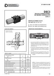
7 - OVERALL AND MOUNTING DIMENSIONS<br />
7.1 - Body module<br />
PARALLEL CONFIGURATION<br />
<strong>BD6</strong>P<br />
dimensions in mm<br />
(n° 3 through holes)<br />
A and B lines<br />
SERIES CONFIGURATION<br />
<strong>BD6</strong>S<br />
(n° 3 through holes)<br />
1 Mounting surface with sealing rings:<br />
<strong>BD6</strong>P n. 2 OR type 2043 (10.82x1.78)<br />
<strong>BD6</strong>S n. 1 OR type 2043 (10.82x1.78)<br />
2 <strong>Co</strong>il removal space<br />
3 Electrical connector type DIN 43650<br />
(drawing with standard type K1 - for<br />
other connections see par. 8)<br />
4 <strong>Co</strong>nnector removal space<br />
5 Locking ring with boot protected<br />
manual override<br />
6 Identification label<br />
A and B ports with threads<br />
44 100/110 ED 8/16
<strong>BD6</strong><br />
SERIES 20<br />
7.2 - Inlet modules for parallel configuration<br />
1 Pressure control valve<br />
2 Locking nut: spanner 19<br />
3 <strong>Co</strong>untersunk hex<br />
adjustment screw:<br />
spanner 6 (standard)<br />
Clockwise rotation to<br />
increase pressure<br />
4 Mounting surface without<br />
sealing rings:<br />
OR on the body module.<br />
5 P and T: 3/8” BSP<br />
6 Pressure gauge port:<br />
1/4” BSP<br />
7 Poppet-type solenoid<br />
valve for unloading<br />
8 Hexagonal: spanner 27<br />
tightening torque 50 Nm<br />
9 <strong>Co</strong>il removal space<br />
10 Electrical connector type<br />
DIN 43650 (drawing with<br />
standard type K1 - for<br />
other connections see<br />
paragraph 8)<br />
11 <strong>Co</strong>nnector removal space<br />
12 Maximum screw stroke<br />
13 Identification label<br />
<strong>BD6</strong>P-F*<br />
(n° 3 through holes)<br />
dimensions in mm<br />
<strong>BD6</strong>P-FK*<br />
(n° 3 through holes)<br />
44 100/110 ED 9/16
<strong>BD6</strong><br />
SERIES 20<br />
7.3 - Inlet module <strong>BD6</strong>S-F* for series configuration<br />
<strong>BD6</strong>S-F*<br />
(n° 3 through holes)<br />
1 Pressure control valve<br />
2 Locking nut: spanner 19<br />
3 <strong>Co</strong>untersunk hex<br />
adjustment screw:<br />
spanner 6 (standard)<br />
Clockwise rotation to<br />
increase pressure<br />
4 Mounting surface without<br />
sealing rings:<br />
OR on the body module.<br />
5 P and T: 3/8” BSP<br />
6 Pressure gauge port:<br />
1/4” BSP<br />
7 Maximum screw stroke<br />
8 Identification label<br />
7.4 - End modules<br />
PARALLEL<br />
CONFIGURATION<br />
<strong>BD6</strong>P-R<br />
(n° 3 through holes)<br />
dimensions in mm<br />
1 Mounting surface with sealing<br />
rings:<br />
N. 2 OR type 2043<br />
(10.82x1.78) 90 Shore<br />
2 T1 outlet: 3/8” BSP<br />
3 Identification label<br />
SERIES<br />
CONFIGURATION<br />
<strong>BD6</strong>S-R1<br />
(n° 3 through holes)<br />
44 100/110 ED 10/16
<strong>BD6</strong><br />
SERIES 20<br />
8 - INSTALLATION<br />
<strong>Co</strong>nfigurations with centering and return springs can be mounted in any position.<br />
9 - ELECTRIC CONNECTIONS<br />
connection for DIN 43650 connector code K1<br />
connection for AMP JUNIOR connector type code K2<br />
outgoing cable connections code K4<br />
connection for DEUTSCH DT04-2P male connector type<br />
code K7<br />
19.8<br />
10<br />
connection for AMP SUPER SEAL (two contacts) connector type<br />
code K8<br />
13.8<br />
4.2<br />
10 - ELECTRIC CONNECTORS<br />
The solenoid valves are supplied without connectors.For coils with standard electrical connections K1 type (DIN 43650) the connectors can be<br />
ordered separately. For the identification of the connector type to be ordered please see cat. 49 000.<br />
For K2, K7 and K8 connection type the relative connectors are not available.<br />
44 100/110 ED 11/16
<strong>BD6</strong><br />
SERIES 20<br />
11 - <strong>AS</strong>SEMBLED VALVE - PARALLEL CONFIGURATION<br />
11.1 - Identification code<br />
<strong>BD6</strong> - P - / / R / 20 -<br />
Bankable directional<br />
control valve<br />
Parallel configuration<br />
No. of body modules<br />
Inlet module<br />
F = with pressure control valve<br />
FK = with pressure control valve<br />
and unloading valve<br />
Pressure adjustment range:<br />
140 = up to 140 bar<br />
210 = up to 210 bar<br />
280 = up to 280 bar<br />
Spool type:<br />
Enter the spool type.<br />
See the available spools at paragraph 1.3<br />
Repeat for each module.<br />
Blind end plate<br />
Series no.: (the overall and mounting<br />
dimensions remain unchanged from 20 to 29)<br />
<strong>Co</strong>il electrical connection:<br />
(see paragraph 9)<br />
K1 = plug for connector type<br />
DIN 43650 (standard)<br />
K2 = plug for connector type<br />
AMP JUNIOR<br />
K4 = outgoing cables<br />
K7 = plug for connector type<br />
DEUTSCH DT04-2P male<br />
K8 = plug for connector type<br />
AMP SUPER SEAL<br />
<strong>Co</strong>il type<br />
D12 = 12 V direct current<br />
D24 = 24 V @ (standard)<br />
R110 = 110 V rectified current<br />
R230 = 230 V @<br />
D00 = Valve supplied without coils<br />
(see par. 1.1 for available coils).<br />
Locking rings are supplied together<br />
with valves.<br />
Seals:<br />
N = NBR seals for mineral oil (standard)<br />
V = FPM seals for special fluids<br />
<strong>Co</strong>ding example:<br />
<strong>BD6</strong>-P4-F140/S1-S1-S1-S1/R/20N-D24K1: assembled valve includes: inlet module with pressure control valve with adjustment up<br />
to 140 bar; 4 body modules S1; blind end plate; NBR seals, 24V DC coils and K1 connection.<br />
<strong>BD6</strong>-P3-FK280/S1-C3-S1/R/20N-D24K1: assembled valve includes: inlet module with pressure control valve with adjustment up to<br />
280 bar and unloading valve; 1 st body module with spool S1, 2 nd body module with spool C3 and 3 th body module with spool S1; blind<br />
end plate; NBR seals, 24V DC coils and K1 connection.<br />
11.2 - Hydraulic symbols and connection scheme<br />
PARALLEL CONNECTION<br />
44 100/110 ED 12/16
<strong>BD6</strong><br />
SERIES 20<br />
12 - <strong>AS</strong>SEMBLED VALVE - SERIES CONFIGURATION<br />
12.1 - Identification code<br />
<strong>BD6</strong> - S - F / / R1 / 20 -<br />
Bankable directional<br />
control valve<br />
Series configuration<br />
No. of body modules<br />
Inlet module<br />
with pressure relief control valve<br />
Pressure adjustment range:<br />
140 = up to 140 bar<br />
210 = up to 210 bar (NOTE)<br />
Spool type:<br />
Enter the spool type.<br />
See the available spools at paragraph 1.4<br />
Repeat for each module.<br />
Outlet plate with T1 port 3/8” BSP threaded<br />
Series no.: (the overall and mounting<br />
dimensions remain unchanged from 20 to 29)<br />
<strong>Co</strong>il electrical connection:<br />
(see paragraph 9)<br />
K1 = plug for connector type<br />
DIN 43650<br />
K2 = plug for connector type<br />
AMP JUNIOR<br />
K4 = outgoing cables<br />
K7 = plug for connector type<br />
DEUTSCH DT04-2P<br />
male<br />
K8 = plug for connector type<br />
AMP SUPER SEAL<br />
<strong>Co</strong>il type<br />
D12 = 12 V<br />
D24 = 24 V direct current<br />
D28 = 28 V A<br />
R110 = 110 V<br />
rectified current<br />
R230 = 230 V @<br />
D00 = valve supplied without coils.<br />
Locking rings are supplied together<br />
with valves.<br />
Seals:<br />
N = NBR seals for mineral oil (standard)<br />
V = FPM seals for special fluids<br />
NOTE: Screwing completely the pressure control valve, the reachable max operating pressure is 240 bar with Q ≥ 5 l/min<br />
<strong>Co</strong>ding example:<br />
<strong>BD6</strong>-S3-F140/S4-SB4-SA4/R1/20N-D24K1: assembled valve includes: inlet module with pressure control relief valve, with<br />
adjustment up to 140 bar, 1 st body module with spool S4, 2 nd body module with spool SB4 and 3 th body module with spool SA4; outlet<br />
plate; NBR seals, 24V DC coils and K1 connection.<br />
12.2 - Hydraulic symbols and connection scheme<br />
SERIES CONNECTION<br />
T1<br />
T1<br />
44 100/110 ED 13/16
<strong>BD6</strong><br />
SERIES 20<br />
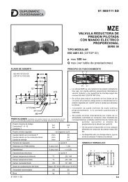
13 - OVERALL DIMENSION OF THE <strong>AS</strong>SEMBLED VALVE IN PARALLEL CONFIGURATION<br />
dimensions in mm<br />
1 Fixing foot<br />
2 Inlet module<br />
3 Valve bodies<br />
modules A B C<br />
2 180 206 140<br />
3 220 246 180<br />
4 260 286 220<br />
5 300 326 260<br />
6 340 366 300<br />
4 End plate<br />
5 Pressure gauge port:<br />
1/4” BSP<br />
6 Poppet-type solenoid<br />
valve for unloading<br />
(FK version)<br />
7 Identification label<br />
44 100/110 ED 14/16
<strong>BD6</strong><br />
SERIES 20<br />
14 - OVERALL DIMENSION OF THE <strong>AS</strong>SEMBLED VALVE IN SERIES CONFIGURATION<br />
dimensions in mm<br />
1 Fixing foot<br />
modules A B C<br />
2 185 211 145<br />
3 225 241 185<br />
4 265 281 225<br />
5 305 321 265<br />
6 345 361 305<br />
2 Inlet module<br />
3 Valve bodies<br />
4 Outlet plate<br />
5 Pressure gauge port:<br />
1/4” BSP<br />
6 Identification label<br />
44 100/110 ED 15/16
<strong>BD6</strong><br />
SERIES 20<br />
DUPLOMATIC OLEODINAMICA S.p.A.<br />
20015 PARABIAGO (MI) • Via M. Re Depaolini 24<br />
Tel. +39 0331.895.111<br />
Fax +39 0331.895.339<br />
www.duplomatic.com • e-mail: sales.exp@duplomatic.com<br />
44 100/110 ED 16/16