You also want an ePaper? Increase the reach of your titles
YUMPU automatically turns print PDFs into web optimized ePapers that Google loves.
I<br />
P<br />
U<br />
L<br />
L<br />
P<br />
U<br />
S<br />
H<br />
O<br />
0°<br />
15°<br />
30°<br />
4<br />
ASSEMBLY<br />
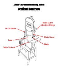
ADJUSTING UPPER BLADE GUIDE ASSEMBLY<br />
See Figures 32 - 33.<br />
• Unplug the saw and remove switch key.<br />
• Loosen blade guard adjustment knob and raise or lower<br />
upper blade guide assembly to just above the material<br />
being cut.<br />
• Tighten blade guard adjustment knob. Make sure blade<br />
guides are still flat to the blade. If adjustment is necessary,<br />
loosen blade guard adjustment knob and rotate assembly<br />
until blade guides are flat to the blade.<br />
• The upper blade guide is spring loaded. To adjust the<br />
tension on the spring, remove blade guard adjustment<br />
knob, tighten or loosen set screw until desired tension is<br />
reached, and replace blade guard adjustment knob.<br />
ADJUSTING UPPER BLADE GUIDES AND<br />
THRUST BEARING<br />
See Figures 33 - 34.<br />
WARNING:<br />
Blade guard has been removed for picture clarity.<br />
Never operate the band saw without all guards in<br />
place and in working order. Failure to do so could<br />
result in possible serious personal injury.<br />
• Unplug the saw and remove switch key.<br />
• Blade must already be tensioned and tracking properly.<br />
• Loosen thumb screws and move blade guides as close to<br />
the blade as possible without pinching it. The thickness<br />
of a dollar bill on each side of blade is a good rule of<br />
thumb.<br />
• Tighten thumb screws.<br />
• Loosen thumb screw and turn knurled knob to move<br />
the blade guide bracket in or out until the front edge of<br />
the blade guides are just behind the “gullets” of the saw<br />
teeth.<br />
• Tighten thumb screw.<br />
• Loosen thumb screw and turn knurled knob to move the<br />
thrust bearing in or out until the bearing is 1/64 in. behind<br />
the blade.<br />
• Tighten thumb screw.<br />
• Blade thrust bearing should be adjusted so that the<br />
back edge of the blade overlaps the front face of the ball<br />
bearing approximately 1/8 in. To change position of the<br />
bearing, remove screw bearing, and back off knurled knob<br />
completely to remove the bearing shaft. Notice the bearing<br />
holder on the shaft is eccentric. Reinstall the bearing shaft,<br />
the bearing, and the screw. Examine the overlap between<br />
the bearing face and the blade. Change the position of<br />
the bearing shaft until the overlap is approximately 1/8<br />
in.<br />
ON<br />
OFF<br />
BLADE GUARD<br />
UPPER<br />
BLADE<br />
GUIDES<br />
SAW BLADE<br />
1/64 IN.<br />
SAW BLADE<br />
10°<br />
P<br />
ULL<br />
KNURLED KNOB<br />
BEARING<br />
SCREW<br />
BLADE GUARD<br />
ADJUSTMENT KNOB<br />
SET SCREW<br />
WORKPIECE<br />
SAW BLADE<br />
GULLET<br />
THUMB SCREWS<br />
THUMB SCREWS<br />
THRUST BEARING<br />
KNURLED KNOBS<br />
THUMB<br />
SCREW<br />
THUMB SCREW<br />
BLADE GUIDE<br />
ASSEMBLY<br />
Fig. 32<br />
BLADE<br />
GUIDES<br />
Fig. 33<br />
1/8 IN.<br />
KNURLED KNOB<br />
BEARING SHAFT<br />
Fig. 34<br />
23