OPERATOR'S MANUAL - Ridgid
OPERATOR'S MANUAL - Ridgid OPERATOR'S MANUAL - Ridgid
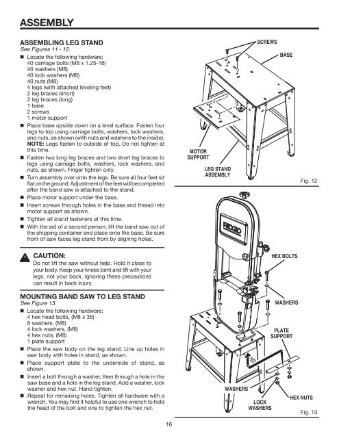
ASSEMBLY ASSEMBLING LEG STAND See Figures 11 - 12. • Locate the following hardware: 40 carriage bolts (M8 x 1.25-16) 40 washers (M8) 40 lock washers (M8) 40 nuts (M8) 4 legs (with attached leveling feet) 2 leg braces (short) 2 leg braces (long) 1 base 2 screws 1 motor support • Place base upside down on a level surface. Fasten four legs to top using carriage bolts, washers, lock washers, and nuts, as shown (with nuts and washers to the inside). NOTE: Legs fasten to outside of top. Do not tighten at this time. • Fasten two long leg braces and two short leg braces to legs using carriage bolts, washers, lock washers, and nuts, as shown. Finger tighten only. • Turn assembly over onto the legs. Be sure all four feet sit flat on the ground. Adjustment of the feet will be completed after the band saw is attached to the stand. • Place motor support under the base. • Insert screws through holes in the base and thread into motor support as shown. • Tighten all stand fasteners at this time. • With the aid of a second person, lift the band saw out of the shipping container and place onto the base. Be sure front of saw faces leg stand front by aligning holes. MOTOR SUPPORT LEG STAND ASSEMBLY SCREWS BASE Fig. 12 CAUTION: Do not lift the saw without help. Hold it close to your body. Keep your knees bent and lift with your legs, not your back. Ignoring these precautions can result in back injury. P ULL HEX BOLTS MOUNTING BAND SAW TO LEG STAND See Figure 13. • Locate the following hardware: 4 hex head bolts, (M8 x 35) 8 washers, (M8) 4 lock washers, (M8) 4 hex nuts, (M8) 1 plate support • Place the saw body on the leg stand. Line up holes in saw body with holes in stand, as shown. • Place support plate to the underside of stand, as shown. • Insert a bolt through a washer, then through a hole in the saw base and a hole in the leg stand. Add a washer, lock washer and hex nut. Hand tighten. • Repeat for remaining holes. Tighten all hardware with a wrench. You may find it helpful to use one wrench to hold the head of the bolt and one to tighten the hex nut. WASHERS LOCK WASHERS WASHERS PLATE SUPPORT HEX NUTS Fig. 13 16
ASSEMBLY MOUNTING THE MOTOR ASSEMBLY See Figure 14. • Locate the following items: 4 hex bolts, (M8 x 35) 8 washers, (M8) 4 lock washers, (M8) 4 hex nuts, (M8) 4 rubber grommets 1 motor with switch assembly • To mount motor, place four rubber grommets over holes in leg stand. NOTE: Use of rubber grommets is essential for eliminating excessive vibration. LARGE PULLEY STRAIGHT EDGE SET SCREW • Set motor on rubber grommets and fasten to leg stand using hex head bolts, washers, lock washers, and hex nuts, as shown. Do not tighten at this time. INSTALLING THE V-BELT See Figures 15 - 17. MOTOR PULLEY SET SCREW Fig. 15 • Locate the following item: 1 V-belt V - BELT • Align the inside edge of the motor pulley with the inside edge of the large pulley using a straight edge. With a 3mm hex wrench, adjust one or both pulleys by loosening the set screw and moving the pulley(s) until they line up with each other. Tighten set screws. • Place V-belt over both pulleys. • Tension V-belt by moving motor away from the saw body and tighten the motor mount nuts. Do not overtighten motor mount bolts. Tighten just enough to tension belt. Belt is properly tensioned when finger pressure between the two pulleys causes approximately 1/2 in. deflection. MOTOR HEX BOLTS SAW BODY TENSION DIRECTION Fig. 16 PROPER TENSION APPROXIMATELY 1/2 IN. WASHERS RUBBER GROMMETS WASHERS LOCK WASHERS HEX NUTS Fig. 14 Fig. 17 17
- Page 1 and 2: ON I P U L L P U S H O 10° 0° 15
- Page 3 and 4: GENERAL SAFETY RULES WARNING: Read
- Page 5 and 6: SYMBOLS Some of the following symbo
- Page 7 and 8: GLOSSARY OF TERMS Bevel Cut A cutti
- Page 9 and 10: ELECTRICAL CHANGING MOTOR VOLTAGE S
- Page 11 and 12: FEATURES KNOW YOUR BAND SAW See Fig
- Page 13 and 14: LOOSE PARTS The following items are
- Page 15: ASSEMBLY UNPACKING This product req
- Page 19 and 20: I ASSEMBLY MOUNTING THE SWITCH BOX
- Page 21 and 22: ASSEMBLY • Replace throat plate a
- Page 23 and 24: I P U L L P U S H O 0° 15° 30° 4
- Page 25 and 26: OPERATION WARNING: Do not allow fam
- Page 27 and 28: OPERATION TILTING THE TABLE See Fig
- Page 29 and 30: I L P ADJUSTMENTS • Rotate guard
- Page 31 and 32: MAINTENANCE LUBRICATION All the bea
- Page 33 and 34: TROUBLESHOOTING Problem Cause Solut
- Page 35 and 36: WARRANTY RIDGID ® HAND HELD AND ST
ASSEMBLY<br />
ASSEMBLING LEG STAND<br />
See Figures 11 - 12.<br />
• Locate the following hardware:<br />
40 carriage bolts (M8 x 1.25-16)<br />
40 washers (M8)<br />
40 lock washers (M8)<br />
40 nuts (M8)<br />
4 legs (with attached leveling feet)<br />
2 leg braces (short)<br />
2 leg braces (long)<br />
1 base<br />
2 screws<br />
1 motor support<br />
• Place base upside down on a level surface. Fasten four<br />
legs to top using carriage bolts, washers, lock washers,<br />
and nuts, as shown (with nuts and washers to the inside).<br />
NOTE: Legs fasten to outside of top. Do not tighten at<br />
this time.<br />
• Fasten two long leg braces and two short leg braces to<br />
legs using carriage bolts, washers, lock washers, and<br />
nuts, as shown. Finger tighten only.<br />
• Turn assembly over onto the legs. Be sure all four feet sit<br />
flat on the ground. Adjustment of the feet will be completed<br />
after the band saw is attached to the stand.<br />
• Place motor support under the base.<br />
• Insert screws through holes in the base and thread into<br />
motor support as shown.<br />
• Tighten all stand fasteners at this time.<br />
• With the aid of a second person, lift the band saw out of<br />
the shipping container and place onto the base. Be sure<br />
front of saw faces leg stand front by aligning holes.<br />
MOTOR<br />
SUPPORT<br />
LEG STAND<br />
ASSEMBLY<br />
SCREWS<br />
BASE<br />
Fig. 12<br />
CAUTION:<br />
Do not lift the saw without help. Hold it close to<br />
your body. Keep your knees bent and lift with your<br />
legs, not your back. Ignoring these precautions<br />
can result in back injury.<br />
P<br />
ULL<br />
HEX BOLTS<br />
MOUNTING BAND SAW TO LEG STAND<br />
See Figure 13.<br />
• Locate the following hardware:<br />
4 hex head bolts, (M8 x 35)<br />
8 washers, (M8)<br />
4 lock washers, (M8)<br />
4 hex nuts, (M8)<br />
1 plate support<br />
• Place the saw body on the leg stand. Line up holes in<br />
saw body with holes in stand, as shown.<br />
• Place support plate to the underside of stand, as<br />
shown.<br />
• Insert a bolt through a washer, then through a hole in the<br />
saw base and a hole in the leg stand. Add a washer, lock<br />
washer and hex nut. Hand tighten.<br />
• Repeat for remaining holes. Tighten all hardware with a<br />
wrench. You may find it helpful to use one wrench to hold<br />
the head of the bolt and one to tighten the hex nut.<br />
WASHERS<br />
LOCK<br />
WASHERS<br />
WASHERS<br />
PLATE<br />
SUPPORT<br />
HEX NUTS<br />
Fig. 13<br />
16


