GMH G ZZ 9 - Magnet-Schultz
GMH G ZZ 9 - Magnet-Schultz
GMH G ZZ 9 - Magnet-Schultz

Create successful ePaper yourself
Turn your PDF publications into a flip-book with our unique Google optimized e-Paper software.
SPEZIAlFABRIk FüR ElEkTROMAGNETISCHE APPARATE<br />
DC holding magnet<br />
Optionally with or without armature<br />
Optionally with polished or zinc-coated pole face<br />
� According to DIN VDE 0580<br />
� High holding force<br />
� Increasing force vs. stroke characteristic<br />
� Gimbal mounted armature<br />
� Exciter coil corresponds to insulation class B<br />
� Electrical connection and protection class<br />
with duly executed installation<br />
� with 2 pole terminal<br />
Protection class according to DIN VDE / EN 60529 – IP 20<br />
� with free flexible lead ends<br />
Protection class according to DIN VDE 0470 / EN 60529 – IP 00<br />
� Size 020:<br />
Fastening via central thread at the reverse side<br />
� Size 025 to 100:<br />
Fastening via 3 tapped holes at the reverse side or central thread<br />
� Pole face optionally polished or zinc-coated<br />
� Protection class IP 65 on request<br />
� Application examples:<br />
Machine construction, fixture construction, materials-handling<br />
handling technology, door holding devices, interlocking of all sorts,<br />
solenoids for short strokes<br />
QUALITY SINCE 1912<br />
<strong>GMH</strong> G <strong>ZZ</strong><br />
<strong>Magnet</strong>-<strong>Schultz</strong> GmbH & Co. KG • Postfach 1665 • D 87686 Memmingen • Allgäuer Straße 30 • D 87700 Memmingen<br />
Telefon ++49 (0) 8331 10 40 • Telefax ++49 (0) 8331 10 43 33 • info@<strong>Magnet</strong>-<strong>Schultz</strong>.de • www.<strong>Magnet</strong>-<strong>Schultz</strong>.com<br />
9<br />
Product group<br />
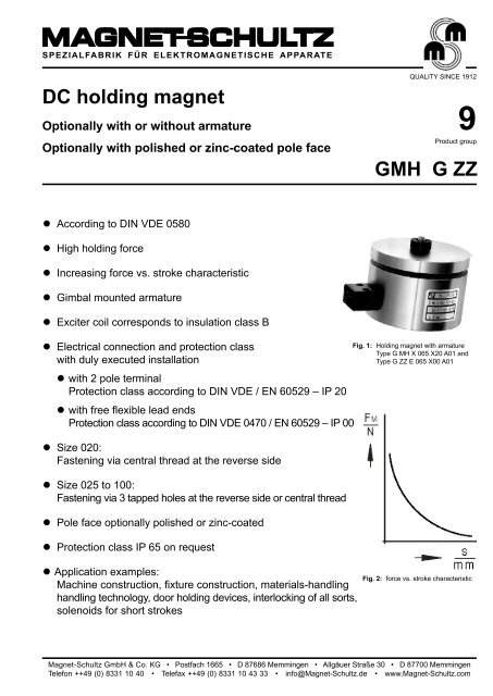
Fig. 1: Holding magnet with armature<br />
Type G MH X 065 X20 A01 and<br />
Type G <strong>ZZ</strong> E 065 X00 A01<br />
Fig. 2: force vs. stroke characteristic
QUALITY SINCE 1912<br />
The normal operating temperature is based on:<br />
a) Rated voltage 24 V<br />
b) Operating mode S1 100%<br />
c) Reference temperature 35° C<br />
d) Mounting on heat-insulating base<br />
2<br />
Technical data<br />
G MH X 020 025 030 040 050 065 080 100<br />
Operating mode S1 100% S1 100% S1 100% S1 100% S1 100% S1 100% S1 100% S1 100%<br />
Rated power P20 (W) 1,9 3,2 4 5,6 6,2 9,8 12,4 17<br />
Solenoid weight mM (kg) 0,025 0,07 0,1 0,22 0,38 0,75 1,3 2,2<br />
Armature weight mA (kg) 0,007 0,012 0,029 0,05 0,1 0,21 0,4 0,74<br />
Armature thickness (mm) 2,5 3 5 5 6 8 10 12<br />
Armature diameter Ø (mm) 20 25 30 40 50 65 080 100<br />
Stroke s (mm) <strong>Magnet</strong>ic force F M (N)<br />
... A01 (polished pole face) 0 88 150 280 520 800 1480 2280 3700<br />
... A11 (zinc-coated pole face) 0 80 135 250 470 720 1330 2050 3330<br />
0,1 10 36,3 70 275 569 1128 1942 3140<br />
0,16 6 18,2 38 157 373 883 1600 2747<br />
0,25 2,1 9,8 20 80 216 618 1256 2354<br />
0,4 0,5 3,5 10 30 93 294 657 1520<br />
0,6 —- 1,8 5 14 41 132 314 804<br />
1,0 —- 0,9 2 6,2 18 61 128 324<br />
1,6 —- —- —- 2,6 7 18 45 137<br />
2,5 —- —- —- 1,3 2,2 10 18 58<br />
4 —- —- —- 0,5 0,8 3,2 9,8 26<br />
6 —- —- —- —- 0,4 2,6 4,9 11<br />
1) <strong>Magnet</strong>ic force F at stroke of 0mm<br />
M<br />
with armature G <strong>ZZ</strong> E for . A01 70 130 230 420 700 1200 1850 3000<br />
for ..A11 63 115 210 380 630 1080 1660 2700<br />
1) The armatures are corrosion protected through nickel-coating. The nickel-coat which is not magnetically conducting causes an air gap, so the<br />
above mentioned magnetic forces can be measured. The adhesive force is of 5% of the magnetic force with a stroke of 0mm. The external return<br />
forces must be above this adhesive force with a sufficient safety margin.<br />
Rated voltage 24 V, the exciter coil can be adjusted to a rated<br />
voltage of<br />
110 V for size 020 up to 030,<br />
250 V for size 040 up to 100<br />
The force values indicated in the tables refer to 90% of the rated<br />
voltage (Un = 24 V, for other voltages deviations of magnetic<br />
force may occur) and to the normal operating temperature.<br />
Due to natural dispersion the force values may deviate by ± 10%<br />
from the values indicated in the tables.<br />
Please make sure that the described devices are suitable for<br />
your application. Please find further details and definitions in<br />
our -Technical Explanation or, respectively, in VDE 0580.<br />
In the interest of a low surface temperature, the excessive temperature<br />
of the devices is ∆ υ 32 = 60 K. The magnetic force values<br />
are measured using a specimen made of 9 S Mn 28 with plane<br />
ground surface and a surface roughness of 15 mm max. On request<br />
an increase of the magnetic force is possible by a special<br />
adjustment of the winding. If the specimen thickness is small,<br />
the magnetic force is reduced. The use of materials with other<br />
permeability or bad surface quality may cause higher deviations<br />
of the rated force.<br />
The pole face of types …A01 is polished. This causes higher<br />
holding forces at increased susceptibility to corrosion. In case that<br />
due to the ambient conditions corrosion on the pole face must be<br />
expected, we recommend using type …A11 with zinc-coated pole<br />
face but slightly reduced holding forces.<br />
Note on the RoHS guideline 2002/95/EC<br />
The devices presented in this document do not fall into the scope of<br />
regulation 2002/95/EC (RoHS) and do not become part of products<br />
which fall into the scope according to our state of information. In<br />
case of surfaces zinc coating with yellow chromating and zinc<br />
iron with black chromating separate agreements are necessary<br />
for application according RoHS.<br />
By edition of the present list, all former unit lists lose their validity especially regarding performance ratings
d1 l2<br />
Dimension tables<br />
Solenoid without armature<br />
d1 h1<br />
a2 a1 b<br />
t1<br />
t1<br />
t2<br />
t2<br />
d2<br />
d2<br />
l1<br />
l1<br />
l3<br />
Terminals<br />
Specimen<br />
(armature)<br />
s<br />
s<br />
Holding face<br />
Fig. 3: Type G MH X 025 X 20 A01 / A11<br />
to G MH X 100 X 20 A01 / A11<br />
Holding face<br />
d3<br />
d3<br />
e<br />
e<br />
Fig. 4: Type G MH X 020 X 00 A01 / A11<br />
to G MH X 100 X 00 A01 / A11<br />
2 pole terminal<br />
clamp<br />
Illustrations without guarantee – modifications reserved<br />
G MH X<br />
Size 020 025 030 040 050 065 080 100<br />
Dim. Dimensions in mm<br />
a 1 —- 13,5 13,5 13,5 13,5 13,5 13,5 13,5<br />
a 2 —- 4,5 5,6 6 6 7 8,5 11<br />
b —- 19 19 19 19 19 19 19<br />
d 1 20 25 30 40 50 65 80 100<br />
d 2 —- M3 M3 M4 M4 M5 M6 M6<br />
d 3 M4 M4 M5 M5 M5 M8 M8 M10<br />
e —- 15 18 26 34 40 50 75<br />
h 1 —- 16 16 16 16 16 16 16<br />
l 1 15 20 24 27 30 35 38 43<br />
l 2 150 150 150 150 150 150 150 150<br />
l 3 10,5 11,4 15 17,4 20,4 24,4 25,8 28,3<br />
t 1 —- 3 4 4 4 5 7 7<br />
t 2 4 6 5 8 8 12 12 15<br />
Size 020 is not available with terminal clamp.<br />
Information about the technical harmonisation<br />
directives within the ESM (European Single Market)<br />
Solenoids belonging to this product range are classed in the low<br />
voltage directive 73/23 EEC. To guarantee the protection targets<br />
of this directive, products are manufactured and inspected according<br />
to the valid edition of DIN VDE 0580. This is also regarded<br />
as manufacturer’s declaration of conformity.<br />
Information about EMC directive 89/336 EEC<br />
QUALITY SINCE 1912<br />
The here shown solenoids are no ready for use devices in the<br />
sense of DIN VDE 0580.The general requirements and protective<br />
measures to be taken by the user are included in DIN VDE 0580.<br />
The use of the shown devices in safety relevant applications<br />
requires always the written agreement of MSM.<br />
Solenoids do not come within the scope of the EMC directive because<br />
they don’t emit electromagnetic disturbances in the sense<br />
of the directive and because their operation is not disturbed by<br />
electromagnetic disturbances. The user has to secure the compliance<br />
with the EMC directive by appropriate wiring.<br />
Examples for protection circuits can be taken from the corresponding<br />
technical documents.<br />
3
QUALITY SINCE 1912<br />
Armature for solenoids<br />
Solenoid<br />
Fig. 5: Type G <strong>ZZ</strong> E 020 X 00 A01<br />
to G <strong>ZZ</strong> E 100 X 00 A01<br />
(size 020-030: ... D01)<br />
Order example<br />
l5<br />
l4<br />
l6<br />
Permanent holding magnets see part lists<br />
G MP and G MP ... B01.<br />
d5<br />
d4<br />
(Holding magnet without armature)<br />
Type G MH X 050 X20 A01<br />
Voltage 24 V DC<br />
Operating mode S1 (100 %)<br />
(Holding magnet with armature)<br />
Type G MH X 050 X20 A01<br />
G <strong>ZZ</strong> E 050 X00 A01<br />
Voltage 24 V DC<br />
Operating mode S1 (100 %)<br />
d3<br />
Subject to our standard conditions.<br />
G <strong>ZZ</strong> E<br />
Size 020 025 030 040 050 065 080 100<br />
Dim. Dimensions in mm<br />
d 3 20 25 30 40 50 65 80 100<br />
d 4 7 8 10,5 10,5 10,5 13,5 16 21,5<br />
d 5 M2,5 M3 M4 M4 M4 M5 M6 M8<br />
l 4 8,5 9,5 14 14 15 19 23 26<br />
l 5 2,5 3 5 5 6 8 10 12<br />
l 6 3,5 4,5 6 6 6 7 9 11<br />
Design with pin-socket on request<br />
Type code<br />
Device group<br />
4 Printed in Germany 112008/01 Alt<br />
Series<br />
Modifications<br />
Size in the series<br />
Execution in the series<br />
G MH X 050 X 20 A01<br />
Protection code<br />
Design number A01: polished pole face<br />
A11: zinc-coated pole face<br />
Special designs<br />
Please contact us for the solution of your problems<br />
concerning application. In this case please indicate your<br />
information about the operating conditions in accordance<br />
with the -Technical Explanations.<br />
Please don’t hesitate to contact our responsible technical<br />
office to receive support.