MODEL FIII-SERIES CONTROL INSTALLATION ... - Agencespl.com
MODEL FIII-SERIES CONTROL INSTALLATION ... - Agencespl.com
MODEL FIII-SERIES CONTROL INSTALLATION ... - Agencespl.com

Create successful ePaper yourself
Turn your PDF publications into a flip-book with our unique Google optimized e-Paper software.
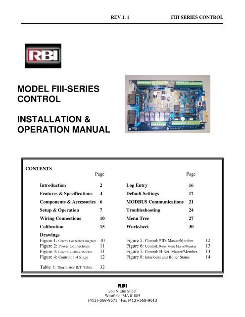
REV 1. 1<br />
<strong>FIII</strong> <strong>SERIES</strong> <strong>CONTROL</strong><br />
<strong>MODEL</strong> <strong>FIII</strong>-<strong>SERIES</strong><br />
<strong>CONTROL</strong><br />
<strong>INSTALLATION</strong> &<br />
OPERATION MANUAL<br />
CONTENTS<br />
Page<br />
Page<br />
Introduction 2 Log Entry 16<br />
Features & Specifications 4 Default Settings 17<br />
Components & Accessories 6 MODBUS Communications 21<br />
Setup & Operation 7 Troubleshooting 24<br />
Wiring Connections 10 Menu Tree 27<br />
Calibration 15 Worksheet 30<br />
Drawings<br />
Figure 1: Control Connection Diagram 10 Figure 5: Control: PID, Master/Member 12<br />
Figure 2: Power Connections 11 Figure 6: Control: Relay Mode Master/Member 13<br />
Figure 3: Control: 4-20ma, Member 11 Figure 7: Control: H-Net, Master/Member 13<br />
Figure 4: Control: 1-4 Stage 12 Figure 8: Interlocks and Boiler Status 14<br />
Table 1: Thermistor R/T Table 32<br />
RBI<br />
260 N Elm Street<br />
Westfield, MA 01085<br />
(413)-568-9571 Fax (413)-568-9613
REV 1.1<br />
<strong>FIII</strong> <strong>SERIES</strong> <strong>CONTROL</strong><br />
Introduction<br />
The <strong>FIII</strong>-<strong>SERIES</strong> Control<br />
The <strong>FIII</strong>-series boiler control is designed to provide the<br />
<strong>FIII</strong>-series of boilers with an integrated boiler<br />
management system on every boiler. Designed for the<br />
Air-Fuel coupled <strong>FIII</strong>-series boilers, the <strong>FIII</strong>-series<br />
control provides for optimized heating efficiency<br />
without the need for a “wall mount control”. This also<br />
eliminates the need for analog control signals such as 4-<br />
20ma control loops and 0-10vdc control voltages, since<br />
the <strong>FIII</strong>-series control method is based on digital<br />
<strong>com</strong>munications. Although the use of analog control<br />
signals is still supported, a higher level of control<br />
precision /repeatability/feedback is gained with digital<br />
<strong>com</strong>munications control.<br />
Optimized heating efficiency is ac<strong>com</strong>plished by setting<br />
the Modulation Maximum (Mod-Max) setting to exploit<br />
the inverse efficiency curve. This value can be adjusted<br />
so that as each boiler is added, it operates at its<br />
maximum turndown. This allows the maximum number<br />
of boilers to operate at their lowest inputs until all<br />
boilers are firing. Once all boilers are firing, full range<br />
modulation control is allowed. An outdoor reset<br />
function is also provided to assist in the optimized<br />
heating efficiency of the <strong>FIII</strong> series boilers.<br />
The <strong>FIII</strong>-series boiler with the <strong>FIII</strong>-series control, can<br />
be operated in multiple ways:<br />
A. As a stand-alone boiler.<br />
B. A boiler in a Boiler Network using the Heat Net<br />
(H-Net ) protocol.<br />
C. A member boiler to a boiler management system<br />
with multiple input control methods.<br />
D. Or as a member in a system with up to (3)<br />
boilers using relay control.<br />
The primary purpose of the control is to maintain the<br />
boiler water temperature at the supply or the header<br />
sensor using a target setpoint. While performing this<br />
task, the control also monitors dedicated external limits<br />
in a limit string and provides an orderly shutdown and<br />
fault indication in the event of a tripped limit. The<br />
monitored limits include a HIGH LIMIT AQUASTAT,<br />
LOW WATER CUTOFF, GAS PRESSURE, FLOW,<br />
IGNITION <strong>CONTROL</strong> fault, GAS VALVE alarm,<br />
VARIABLE FREQUENCY DRIVE alarm, and other<br />
optional or user selectable limits.<br />
NOTE:<br />
The HIGH LIMIT circuit is independent of the<br />
control and shuts down the ignition control and the<br />
boiler if the control board or other <strong>com</strong>ponent of<br />
the boiler was to malfunction. The control will<br />
continue to function and report the fault, but its<br />
ability to control the boiler will end.<br />
Each <strong>FIII</strong>-series boiler employing this control can<br />
function as either a master or a member. This allows one<br />
boiler (master) to be in control of target temperature.<br />
The other boilers (members) only respond to the<br />
<strong>com</strong>mands issued by the boiler in control of the target<br />
temperature (master). If using an external control, all<br />
boilers can be setup as members. The following will<br />
define the roles of master and member.<br />
Master<br />
A boiler be<strong>com</strong>es a master when a temperature<br />
sensor is connected to the J10 “SYS/DHW HEADER”<br />
terminals. The sensor is auto-detected.<br />
The master senses and controls the header/loop water<br />
temperature using a system setpoint. It uses any boilers<br />
it finds (H-Net), or that are defined in the setup menus<br />
to ac<strong>com</strong>plish this. It also monitors the Outside Air<br />
(OA) temperature to provide outdoor reset<br />
functionality. Only one master is allowed in a system.<br />
When operating as a master, the boiler control<br />
provides a stand-alone method using a PID algorithm to<br />
regulate water temperature. This algorithm allows a<br />
single boiler (Master), or multiple (Master + Member)<br />
boilers.<br />
The control algorithm is based upon a control band,<br />
at the center of which is the setpoint. While below the<br />
control band, boilers are staged on and modulated up<br />
until the control band is entered. Once in the control<br />
band, modulation is used to maintain setpoint. Boilers<br />
are shut down only when the top of the band is<br />
breached, or before the top of the band, if the control<br />
anticipates that there is a light load. Timers are also<br />
used to prevent short cycling.<br />
While staging the boilers on, a modulation clamp<br />
MOD MAX – LAST FIRE is used to hold the boilers<br />
at a lower fire rate until the last boiler is fired. Once the<br />
last boiler fires, the modulation clamp is removed and<br />
all boilers are allowed to fire above this clamped<br />
percentage up to 100%. This “boiler efficiency” clamp<br />
is defaulted to 80% and thus limits all of the boilers<br />
individual outputs to 80% until the last boiler fires.<br />
All boilers modulate up and down together always at<br />
the same modulation rate.<br />
MEMBER<br />
A boiler always defaults to the role of member. The<br />
lack of a “SYS/DHW HEADER” sensor (not)<br />
connected to J10 ensures this.<br />
The member senses its supply water, and modulates<br />
based on signals from an external control or master<br />
boiler. When operating as a member, starting, stopping,<br />
Page 2
REV 1.1<br />
<strong>FIII</strong> <strong>SERIES</strong> <strong>CONTROL</strong><br />
and the firing rate are controlled by an external control<br />
or by the master boiler.<br />
If using the H-Net protocol, the system setpoint is<br />
sent from the master, along with the modulation value<br />
to control firing rate. It also receives its <strong>com</strong>mand to<br />
start or stop over the H-Net cable.<br />
The member also continuously monitors its supply<br />
temperature against its operating limit. If the supply<br />
temperature approaches the operating limit temperature<br />
(adjustable), the boilers input control rate is limited and<br />
its modulation value decreases to minimize short<br />
cycling. If the operating limit is exceeded, the boiler<br />
shuts off.<br />
If not using the H-Net protocol, the master or an<br />
external boiler control can send a 4-20ma signal along<br />
with a 4-20ma enable signal to control the firing rate.<br />
The boiler may also be treated as a 4-stage boiler or an<br />
ON-OFF boiler using the dedicated T-inputs.<br />
Page 3
REV 1.1<br />
<strong>FIII</strong> <strong>SERIES</strong> <strong>CONTROL</strong><br />
Features & Specifications<br />
Features Overview<br />
1. Four levels of external control inputs, including modulation and staging that provide application flexibility.<br />
2. Digital Communications Control ( analog 4-20ma and 0-10vdc control supported, but not required).<br />
A. Boiler to Boiler : Heat Net (H-Net)<br />
B. Building Management System (MODBUS, Optional BACNET or LONWORKS) to Boiler<br />
3. Distributed control using the Heat Net (H-Net) protocol for up to 16 boilers, or up to 3 boilers using dedicated<br />
relays. Eliminates the need for “wall mounted” controls.<br />
4. System/Boiler operating status text display<br />
5. Interlock, Event, and System logging with a time stamp.<br />
6. Advanced PID algorithm optimized for the <strong>FIII</strong> series boilers.<br />
7. (4) Dedicated temperature sensor inputs for: Outside Air Temperature, Supply (Outlet) Temperature, Return<br />
Temperature (Inlet), and Header Temperature.<br />
8. Automatically detects the optional temperature sensors on power up.<br />
9. Menu driven calibration and setup menus with a bright (Adj.) 4 line Vacuum Fluorescent Display.<br />
10. (8) Dedicated 24vac interlock monitors, and 8 dedicated 120vac system monitors used for diagnostics and<br />
providing feedback of faults and system status.<br />
11. Multiple circulator pump control modes.<br />
12. Combustion Air Damper control with proof time.<br />
13. Optional USB/RS485 network plug-in to allow firmware updates or custom configurations.<br />
14. Optional BACNET or LONWORKS interface.<br />
15. Alarm contacts.<br />
16. Runtime hours.<br />
17. Outdoor Air Reset with programmable ratio.<br />
18. Time of Day clock to provide up to (4) night setback temperatures.<br />
19. Failsafe mode when a Building Management System is controlling setpoint. If <strong>com</strong>munications is lost, the<br />
boiler/system can run off the Local Setpoint.<br />
Page 4
REV 1.1<br />
<strong>FIII</strong> <strong>SERIES</strong> <strong>CONTROL</strong><br />
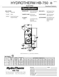
Specifications<br />
Control Microprocessor based PID modulating control ( NOT a safety limit )<br />
Environment<br />
-40 F to 140 F,
REV 1.1<br />
<strong>FIII</strong> <strong>SERIES</strong> <strong>CONTROL</strong><br />
Components & Accessories<br />
Part Number<br />
Component<br />
02-4277 <strong>FIII</strong>-Series Control Board<br />
02-4279 RS485 Communications Board<br />
02-4278 Graphics Display Board<br />
02-3926 Temperature probe (bullet type, 1x.250 inch) ACI/10K-CP-BP<br />
02-4283 Supply, Header, Return Sensors ACI 10k-CP-I-NW<br />
02-4254 Sensor with well ACI CP-I-2.5”<br />
02-4282 Sensor with well ACI CP-I-4”<br />
02-4281 Strap-on sensor ACI 10k-CP-S<br />
02-4280 Outside Air Sensor with Housing ACI 10k-CP-O<br />
42-9529 Installation & Operations Manual<br />
40-5412 RJ45 Communications Cable Assembly, 25 feet<br />
40-5411 Ribbon Cable Assembly (Display Control)<br />
58-1833 10k ohm Calibration Resistor<br />
40-5408 USB Cable Assembly, 6ft<br />
60-5631 Terminal Block Screwdriver<br />
Contact Factory<br />
Contact Factory<br />
MODBUS to BACNET bridge<br />
MODBUS to LONWORKS bridge<br />
Page 6
REV 1.1<br />
<strong>FIII</strong> <strong>SERIES</strong> <strong>CONTROL</strong><br />
Setup & Operation<br />
Control Methods<br />
There are (5) methods for controlling the <strong>FIII</strong> series<br />
boiler. See Figures 1 through Figure 8.<br />
1. The first method is to use the <strong>FIII</strong> series boiler in<br />
its stand-alone modulating method (Local<br />
Control). This method uses a PID algorithm to<br />
maintain a setpoint and is enabled using the<br />
HEAT DEMAND input. (Closing a relay contact<br />
or switch across the HEAT DEMAND input<br />
causes the Master to control all boilers, a<br />
member would control itself using the its supply<br />
sensor)<br />
2. The second method is to view the <strong>FIII</strong> boiler as<br />
four separate boilers, firing at (4) predetermined<br />
rates using the T1, T2, T3, and T4 inputs (stage<br />
control).<br />
3. The third method is to allow a remote 4-20 ma or<br />
0-10 VDC signal to control the firing rate<br />
(modulation) of the boiler using the 4-20ma<br />
input, along with the 4-20ma REMOTE<br />
ENABLE input.<br />
4. The fourth method turns the boiler ON and OFF<br />
@ 100% modulation using the AA terminal.<br />
5. The fifth method uses an RS485 digital<br />
<strong>com</strong>munications cable with the MODBUS<br />
protocol to control the boiler. Writing and<br />
reading registers using MODBUS <strong>com</strong>mands.<br />
When the master boiler or an external control input is<br />
used to control a member boiler (i.e. AA, T1-T4, 4-20ma,<br />
H-Net), a software operating limit on the member boiler<br />
will be used to limit the maximum output of the member<br />
boiler. This operating limit can be adjusted in the<br />
SETPOINTS menu under OPERATING LIMIT. There is<br />
also an associated operating limit band that must be set in<br />
conjunction with the operating limit to help prevent this<br />
LIMIT from being reached. It’s purpose, is to limit the<br />
output of the boiler as it approaches the operating limit. If<br />
the band is set to 10 degrees, then for every degree that it<br />
approaches the operating limit, the maximum output will<br />
be lessened by 10%. With a band of 20 degrees, for every<br />
degree that it approaches the band, the maximum output<br />
will be lessened by 5%. This method minimizes boiler<br />
short cycling when using external inputs. The minimum<br />
setting is 1 degree and effectively turns the limit band<br />
OFF.<br />
The <strong>FIII</strong> series control inputs are prioritized so that<br />
multiple levels of external control can be employed at<br />
the same time. This means that if we are firing the<br />
boiler with a low priority input and a higher priority<br />
input is called for, the boiler will now fire at the higher<br />
priority input. When the high priority input is removed,<br />
the boiler will revert back to the lower priority input<br />
that is still being called.<br />
Priority 1.<br />
Priority 2.<br />
Priority 3.<br />
Priority 4.<br />
Priority 5.<br />
The AA terminal has absolute<br />
control, and if used, will always<br />
fire the boiler at 100% output,<br />
regardless of any other input.<br />
The HEAT DEMAND input is the<br />
next, and provides the means to<br />
operate the boiler in LOCAL<br />
<strong>CONTROL</strong> when an external<br />
control is not present, has failed, or<br />
needs to be enabled or disabled. A<br />
member can override the H-Net<br />
<strong>com</strong>mands using this input.<br />
If a Heat Net (H-Net) Network<br />
cable is connected between boilers,<br />
and one is configured as a<br />
MASTER (requires HEADER<br />
sensor), then the MEMBER boilers<br />
will be controlled over the network<br />
by the MASTER.<br />
The 4-20ma/0-10VDC input in<br />
tandem with the 4-20ma REMOTE<br />
ENABLE input is next. Any signal<br />
over 4.02ma or 2.01VDC will start<br />
and operate the boiler if the<br />
REMOTE ENABLE is closed.<br />
The lowest priority is using the<br />
boiler as (4) stages. These are the<br />
T1, T2, T3, and T4 inputs.<br />
Each of these control methods will now be explained in<br />
more detail:<br />
1. AA Input; HIGH FIRE input Control: The AA<br />
input will fire the boiler at HIGH fire (maximum<br />
output of the boiler). No other inputs can<br />
override this input.<br />
2. LOCAL Control: Closing a contact across the<br />
HEAT DEMAND input starts the boiler. Once<br />
the boiler is started, a PID algorithm is used to<br />
produce a PWM, (P)ulse (W)idth (M)odulation<br />
signal. This signal is used to regulate the boilers<br />
output based on a LOCAL setpoint or a setpoint<br />
derived from an outdoor reset ratio. The<br />
temperature of the water is maintained by<br />
sending this modulating signal to the Variable<br />
Frequency Drive, which in turn controls the<br />
blower motor. Since the main fuel valve is airfuel<br />
coupled to the blower, the speed of the<br />
blower provides the firing rate.<br />
The Local Control includes short cycling<br />
<strong>com</strong>pensation of the PID. When the boiler is<br />
running with a minimum load, a short cycling<br />
condition may exist that will cause the water<br />
Page 7
REV 1.1<br />
<strong>FIII</strong> <strong>SERIES</strong> <strong>CONTROL</strong><br />
temperature to exceed the boiler’s operating<br />
control band. The control is designed to predict<br />
when to start and stop the boiler and keep the<br />
setpoint temperature in, or as close to the control<br />
band as possible. This will help prevent short<br />
cycling of the boiler, and maintain a more<br />
accurate temperature relative to the setpoint.<br />
The Local Control can also use the Outdoor<br />
Reset feature. This feature allows the setpoint to<br />
be changed automatically based on the outside<br />
air temperature. If this feature is used, the control<br />
input: OR OVR (OUTDOOR RESET<br />
OVERRIDE), can be used to override the<br />
Outdoor Reset feature and run from the local<br />
setpoint. A contact closure on the ‘AA’ input can<br />
also override this method.<br />
3. H-Net Control: The Master, on the H-Net<br />
NETWORK can <strong>com</strong>mand the boiler modulation<br />
fire rate of all Member boilers. Closing a relay<br />
contact, switch, or jumper across the HEAT<br />
DEMAND input will enable this method. This<br />
method works like the LOCAL Control on<br />
member boilers, but the Master can call other<br />
boilers to meet its setpoint (system setpoint). The<br />
H-Net cable must be connected and will cause<br />
the amber light on the <strong>com</strong>munications board to<br />
flash ever second. The amber light indicates an<br />
H-Net master is broadcasting control information<br />
and a system heartbeat. The AA terminal and the<br />
HEAT DEMAND input (LOCAL) on a<br />
MEMBER, are the only inputs that will override<br />
the H-Net control.<br />
4. 4-20ma Control: Placing a current source<br />
between the + and – 4-20ma inputs will allow<br />
remote control of the boilers firing rate. A<br />
4.02ma current signal here will start and then fire<br />
the boiler at the minimum fire rate. A 20ma<br />
signal will fire the boiler at the maximum firing<br />
rate. The input current signal is viewed as a<br />
percentage to the boiler from 0 to 100% (0-<br />
20ma). This means that a 20%(4ma) input signal<br />
is required to start the boiler, but since the boiler<br />
is classified as having a 4:1 turn down ratio, the<br />
boiler can only be fired as low as 25% of output.<br />
Any signal between 20% and 25 %, will fire the<br />
boiler at the minimum fire rate. If the<br />
MINIMUM setting of the boiler is set above the<br />
4:1 turndown of 25% (such as 33%), a control<br />
signal change between 25% and 33% will not<br />
change the boilers firing rate. Once the control<br />
signal rises above the MINIMUM fire rate, the<br />
control signal will then affect control of the<br />
boilers fire rate.<br />
Page 8<br />
The AA terminal, the HEAT DEMAND, and the<br />
H-Net NETWORK are the only inputs that will<br />
override the 4-20ma input.<br />
5. STAGE Control: The boiler can also be<br />
operated in 4 separate stages using the inputs T1,<br />
T2, T3, and T4. Its intended use is with an<br />
external stage controller with no analog or<br />
modulation outputs. With a boiler configured as<br />
a member, only that boiler will fire.<br />
a. Closing only one of these contacts tells the<br />
boiler to operate at MINIMUM FIRE.<br />
b. Closing any 2 contacts will fire the boiler<br />
at 1/2 of the maximum output of the<br />
boiler.<br />
c. Closing any 3 contacts will fire the boiler<br />
at 3/4 of the boilers maximum output.<br />
d. Closing all 4 contacts will fire the boiler<br />
at MAXIMUM output (the same rate as<br />
closing the AA input).<br />
NOTE: the maximum output of the boiler is<br />
based on the MAX OUTPUT setting in the<br />
calibration mode and not the nameplate rating.<br />
The AA, HEAT DEMAND (LOCAL) input, the H-Net,<br />
the 4-20ma input will all override the stage control<br />
inputs.<br />
Using the 4-20ma input<br />
The 4-20ma input is designed to operate per the ISA-50.1<br />
standard. It will support Type 2, Type 3, and Type 4<br />
Transmitter/Receiver circuits.<br />
The Type 2 and Type 3 circuit may use the<br />
supplied +24VDC and 24VDC RET connections for the<br />
transmitter, or provide their own power. In either case, the<br />
–ma terminal will need to have a jumper connected to the<br />
adjacent 24VDC RET terminal.<br />
With the type 4 configuration, multiple boilers<br />
(up to 5), may be connected in series using the –ma +ma –<br />
ma +ma scheme (no jumper to 24VDC RET). This allows<br />
one 4-20ma transmitter to control multiple boilers. A freefloating<br />
250 ohm resistor is viewed by the boiler control’s<br />
4-20ma transmitter across the + and –4-20ma terminals<br />
with this method.<br />
The 4-20 ma input uses a 250 ohm sense resistor<br />
to convert the current to a voltage from 1 to 5 volts DC<br />
for the control to use. When a 4.02 ma signal is sensed,<br />
the boiler will initiate a start sequence and fire the boiler<br />
at it’s minimum setting. This is typically 25% of the<br />
boilers output.<br />
If using the RELAY method of operation, the 4-<br />
20ma transmitter output on the MASTER will need to be<br />
connected to the member boilers using the floating 250
ohm method (type 4). The relay contacts on the MASTER<br />
will then be connected to the associated 4-20ma<br />
REMOTE ENABLE inputs on the associated boiler(s).<br />
NOTE<br />
The minimum setting of the boiler is calibrated so<br />
that the minimum PWM signal to control the Blower<br />
motor is 20%. The VFD to blower motor operates<br />
with a control signal from 20% - 80% Pulse Width<br />
Modulation. This PWM signal to the VFD can be<br />
measured using a multimeter. It is a 0–10volt square<br />
wave signal at 110 Hertz. A 20% modulation signal<br />
will read 2.0 VDC, and an 80% modulation signal<br />
will read 8.0 VDC on an RMS multimeter.<br />
Circulator Pump Options<br />
The circulator pump options are intended for the boilers<br />
local circulator pump. The circulator pump is supported<br />
by (3) modes.<br />
1. The first mode will allow the circulator<br />
pump to remain on, unless the control’s<br />
outside high air temperature setting has been<br />
met when using OUTDOOR AIR RESET.<br />
2. The second mode will allow the circulator<br />
pump to be turned on whenever there is a<br />
call for heat (any control input). This mode<br />
will stop the circulator pump when the call<br />
for heat is lost and the pump post purge time<br />
has been satisfied.<br />
3. The third mode allows the inlet sensor<br />
(RETURN) to be used with the outlet sensor<br />
(SUPPLY) to keep the pump on until a delta<br />
(difference) temperature is met. The return<br />
temperature sensor is required for this mode,<br />
since the delta temperature (SUPPLY –<br />
RETURN) measured is across the boiler. In<br />
this mode, the post purge time is also used,<br />
and after the delta temp has been met, the<br />
post purge time needs to expire before the<br />
pump is turned off.<br />
If a flow switch is connected to the WTR FLW<br />
interlock, the <strong>FIII</strong> control will wait up to 10 seconds to<br />
prove flow. If flow is interrupted after it has been<br />
established, an error will be displayed and the boiler<br />
will cycle OFF. As long as there is a call for heat,<br />
every 10 minutes the circulator pump will try to reestablish<br />
flow and start the boiler again.<br />
REV 1.1<br />
<strong>FIII</strong> <strong>SERIES</strong> <strong>CONTROL</strong><br />
temperature. In the case of a single boiler system, the<br />
boiler’s outlet (SUPPLY) sensor will only be needed<br />
(Local Control).<br />
Auxiliary Function Options<br />
If less than 3 boilers are used in a stand-alone (no<br />
external control) configuration, the third boiler relay<br />
contact can be used to control a <strong>com</strong>bustion air damper.<br />
A proof time of up to 4 minutes can be set before the<br />
boiler can start or an alarm condition will occur. If the<br />
boiler configuration is for a single boiler, either the<br />
second or third boiler relays can be used for this option.<br />
Sensors<br />
The <strong>FIII</strong> control supports a standard 10K thermistor.<br />
These sensors can be calibrated to the control by<br />
entering the sensor menu and placing a precision 10k<br />
resistor on an input.<br />
Security<br />
A password can be used to lock out control and setup<br />
features. It can be enabled, but is shipped in the<br />
disabled state.<br />
Diagnostics<br />
The <strong>FIII</strong> control can display and identify faults in a<br />
meaningful way. If an interlock trips, it will be<br />
indicated in the main screen display, along with an<br />
audible alarm and a set of relay contacts will close. A<br />
record of this, with a time stamp, will also be entered<br />
into the log as an aide in the diagnosis of the event. The<br />
log can be downloaded and a histogram used to display<br />
the data TBD.<br />
Open and shorted sensors are checked continuously, so<br />
that in the event of a sensor failure, the system shuts<br />
down and the alarm relay is closed.<br />
Communications<br />
The <strong>FIII</strong> control has the ability to <strong>com</strong>municate using the<br />
MODBUS protocol with a building management system.<br />
Most registers and functions are available through<br />
MODBUS access. Access is allowed using the RS485<br />
CONSOLE connecter on the <strong>com</strong>munication board.<br />
PID Control Algorithm Options<br />
The control algorithm can be used with an outdoor reset<br />
ratio, and can regulate water temperature from the loop<br />
(header temperature), or from the boiler’s outlet<br />
Page 9
REV 1.1<br />
<strong>FIII</strong> <strong>SERIES</strong> <strong>CONTROL</strong><br />
Wiring Connections<br />
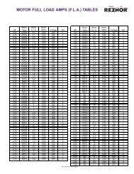
FIGURE 1: <strong>FIII</strong> Series Control Connection Diagram<br />
SPARE 3<br />
LWCO (LOW WATER CUTOFF)<br />
24 VAC Interlocks<br />
VFD (VAR FREQ. DRIVE)<br />
GAS PR (GAS PRESSURE)<br />
SPARE 4<br />
OPERATOR<br />
WTR FLW (WATER FLOW)<br />
AIR PR UV SENSR<br />
PWM OUT to VFD<br />
4-20ma/PWM to remote<br />
Boilers<br />
AIROUTSIDE<br />
Analog Sensors<br />
(Temperature)<br />
WTR OUT (SUPPLY)<br />
WTR IN (RETURN)<br />
SYS/DHW(HEADER)<br />
SPARE 1<br />
4-20ma/0-10vdc<br />
input<br />
24vac Transformer<br />
Connection<br />
Line Power<br />
COMM<br />
Switched Power<br />
B2<br />
B3/DMPR<br />
CIRC<br />
ALARM<br />
AA<br />
Heat D<br />
4-20ma Enable<br />
OR OVR<br />
T1<br />
T2<br />
T3<br />
T4<br />
SPARE 2<br />
24VDC RET<br />
+MA<br />
-MA<br />
24VDC<br />
Communications Board<br />
H-NET<br />
Boiler<br />
Comm<br />
USB to PC<br />
Relay<br />
Contacts<br />
MODBUS<br />
Port RJ45 H-NET<br />
3-wire<br />
MODBUS<br />
Port 3 wire<br />
Control<br />
Inputs<br />
Page 10
REV 1.1<br />
<strong>FIII</strong> <strong>SERIES</strong> <strong>CONTROL</strong><br />
FIGURE 2:<br />
POWER CONNECTIONS<br />
230/240 VAC 60HZ<br />
208 VAC 2 phase<br />
L1<br />
L2<br />
NEUTRAL<br />
OR<br />
120 VAC 60HZ<br />
(Only for use with<br />
120VAC models)<br />
(<strong>FIII</strong>10,<br />
L1<br />
NEUTRAL<br />
FIGURE 3:<br />
Control : 4-20ma, MEMBER<br />
Modulation Control Input<br />
24VDC<br />
4-20ma/0-10vdc -<br />
4-20ma/0-10vdc +<br />
24VDC Return<br />
Jumper in this<br />
position for 4-20ma<br />
Closing Contact here<br />
enables the 4-20 ma<br />
control input.<br />
Page 11
REV 1.1<br />
<strong>FIII</strong> <strong>SERIES</strong> <strong>CONTROL</strong><br />
FIGURE 4:<br />
Control: 1-4 stage boiler, MASTER/MEMBER<br />
Close this contact to run<br />
boiler at High Fire<br />
Stage Control Inputs:<br />
Stage 1, Stage 2,<br />
Stage 3, Stage 4<br />
AA<br />
1 2 3 4<br />
FIGURE 5:<br />
Control: PID, MASTER/MEMBER<br />
Slave: Close to run at Local Setpoint<br />
Master: Close to control all boilers & run<br />
at System Setpoint.<br />
Close this contact to override the<br />
Outdoor Reset slope and run at<br />
the Local/System Setpoint.<br />
Page 12
REV 1.1<br />
<strong>FIII</strong> <strong>SERIES</strong> <strong>CONTROL</strong><br />
FIGURE 6:<br />
Control: Relay Mode MASTER<br />
4-20ma Transmitter<br />
4-20ma - Output<br />
4-20ma + Output<br />
Connect to<br />
boilers 2<br />
and 3<br />
Relay Mode: Enables boiler<br />
2, wire to Boiler 2 Remote<br />
Enable.<br />
All Modes: Alarm Contacts<br />
close during a fault condition.<br />
Relay Mode: Enables Combustion Air<br />
Damper or boiler 3, wire to Boiler 3<br />
Remote Enable or to power<br />
Combustion Air Damper.<br />
All Modes: Enables local<br />
boiler Circulator pump .<br />
FIGURE 7:<br />
Control: H-NET, MASTER/MEMBER<br />
NOTE: J4 can be used instead<br />
of J1. If RJ45 cables/ends are<br />
not available, use shielded wire.<br />
Computer or<br />
Management<br />
System<br />
USB to<br />
Computer<br />
To next<br />
Boiler<br />
H-Link Termination:<br />
Master: always has (2) termination jumpers enabled(Termination) J21,J23.<br />
MEMBER: (farthest) boiler has (2) jumpers enabled(Termination). J21,J23<br />
MODBUS<br />
Always A MEMBER: Terminate last using J3 & J6 (Termination enabled)<br />
H-NET Termination:<br />
Enabled Disabled<br />
J6<br />
J3<br />
J23<br />
J21<br />
Straight Pins<br />
From a<br />
Boiler<br />
Right Angle Pins<br />
NO Termination<br />
Termination<br />
H-NET MODBUS<br />
Page 13
REV 1.1<br />
<strong>FIII</strong> <strong>SERIES</strong> <strong>CONTROL</strong><br />
FIGURE 8:<br />
Interlocks and Boiler Status<br />
Highest priority is<br />
farthest to left as<br />
viewed<br />
Spare for user or Factory<br />
Low Water Cutoff<br />
Variable Frequency Drive<br />
Gas Pressure (High & Low)<br />
Spare for user or Factory<br />
Operator<br />
Water Flow Switch<br />
UV Sensor Air Switch<br />
Priority<br />
1<br />
2<br />
3<br />
4<br />
5<br />
6<br />
7<br />
8<br />
The Highest priority<br />
interlock that opens will be<br />
displayed as the fault.<br />
Low Voltage Interlocks, 24VAC<br />
NOTE: Spare interlocks can be<br />
used as REMOTE interlocks<br />
FACTORY:High<br />
voltage (120VAC)<br />
Interlocks and<br />
Firing status<br />
Page 14
REV 1.1<br />
<strong>FIII</strong> <strong>SERIES</strong> <strong>CONTROL</strong><br />
Calibration<br />
A detailed startup and walkthrough of the<br />
calibration and H-Net setup is provided in the<br />
Programming Examples manual.<br />
The calibration of the <strong>FIII</strong>-series boiler should only<br />
be performed by a licensed technician. To enter the<br />
calibration menus, place the S2 switch on the main<br />
control board to the CAL position.<br />
Be sure to set this switch back to NORM when the<br />
calibration is <strong>com</strong>plete, otherwise no external control<br />
inputs will work (except T1-T4), the display will<br />
always indicate CALIBRATE and some of the runtime<br />
temperatures will not be displayed.<br />
The Minimum Input setting, the Maximum Output<br />
setting, and the Ignition setting can be adjusted in the<br />
calibration displays. The values can be changed while<br />
running ONLY IN MINIMUM FIRE (any, but only<br />
one of the T inputs closed). Prior to ignition, the values<br />
may be changed, but the blower will not operate.<br />
Press the arrow keys until MINIMUM is shown in the<br />
display, along with the minimum percentage value at<br />
which the boiler is to run at min fire. While in Standby<br />
(no call for heat on inputs), the minimum percent may<br />
be preset. To set the minimum rate while running, any<br />
(1), and only (1) of the (T) inputs must be closed in<br />
order to set the boiler to MINIMUM fire. Press the<br />
SELECT key for approximately 1 second. The<br />
Percentage value will start flashing, indicating that it<br />
can be adjusted. Adjust the Minimum value to the<br />
desired setting using the arrow keys. The Minimum<br />
setting is clamped to its lowest rated setting and cannot<br />
be adjusted below this. Once you are done with this<br />
setting, press the SELECT key until the value stops<br />
flashing. The new setting is now saved.<br />
Press the Arrow key to select the IGNITION percent.<br />
The Blower speed will be set here to provide the rate<br />
for ignition. While in Standby (no call for heat on<br />
inputs), the Ignition percent may be preset, before firing<br />
the boiler. To set the ignition rate while running, any<br />
(1), and only (1) of the T inputs must be closed Pressing<br />
the SELECT key here will cause the IGNITION setting<br />
to flash and the boiler will ramp to the ignition setting.<br />
Adjust it using the arrow keys and then press the<br />
SELECT key until the value stops flashing. The new<br />
setting is now saved.<br />
Page 15
Log Entry<br />
The <strong>FIII</strong>-Series control contains a log that records the<br />
major activity in the operation of the boiler<br />
(SNAPSHOT(s) ). This activity includes interlock<br />
faults, boiler starting and stopping events, power cycles,<br />
misc. faults, and types of calls-for-heat (control inputs).<br />
Setting the time clock to an accurate time and date is<br />
very useful when events are recorded, since the control<br />
will time stamp each snapshot.<br />
A snapshot in time of the boiler state is presented via<br />
multiple screens. Each screen snapshot can be stepped<br />
through using the arrow keys. The top line indicates the<br />
time and date the snapshot was taken. In the top right<br />
corner, the snapshot # is displayed so easy indexing can<br />
be done using the arrow keys. The second line displays<br />
the Water temperature of the boiler’s output (supply)<br />
and the Setpoint temperature. The third line displays the<br />
Outside Air temperature, and the Modulation PWM<br />
signal sent to the Variable Frequency drive (20% =min,<br />
80% =Max). The bottom line is used to record the<br />
control state of the boiler. The control state is defined<br />
as the Boiler(s) that is running, the Circulator Pump<br />
state, and the ignition condition (Main Valve, Pilot<br />
Valve, Blower, and the Ignition alarm). The # of boilers<br />
that are displayed is limited to 7 if the boiler is the<br />
MASTER. If boilers #8 and up need to be viewed, the<br />
Boiler Control Pro software will need to be used. The<br />
Last 2 characters on the fourth line indicate the heating<br />
mode the control is in. The modes are:<br />
REV 1.1<br />
NC =<br />
HD =<br />
RM =<br />
HF =<br />
<strong>FIII</strong> <strong>SERIES</strong> <strong>CONTROL</strong><br />
No Call for Heat<br />
Heat Demand (MASTER and Local<br />
modulation control using PID control,<br />
MASTER and MEMBER)<br />
Remote Modulation from 4-20ma input<br />
High Fire from ALL T-inputs closed or the<br />
AA input<br />
1T = Low Fire from any 1 T-input closed (25%<br />
modulation)<br />
2T = Mid Fire from any 2 T-inputs closed (50%<br />
modulation)<br />
3T = Mid High Fire any 3 T-inputs closed (75%<br />
modulation)<br />
LK =<br />
H-Net Control using the Heat-Link<br />
<strong>com</strong>munications cable<br />
The bottom line is also used to indicate an interlock or<br />
limit that has tripped. It may also indicate a sensor that<br />
has failed. When this occurs, the normal bottom line in<br />
the display is not visible, and the sensor fault is<br />
displayed.<br />
The log is primarily used as a troubleshooting and<br />
diagnostic tool, but may be used as a performance tool<br />
to calculate run time cycles.<br />
Time<br />
Stamp<br />
Snapshot<br />
number<br />
Water Temperature Out<br />
Outside Air<br />
Temperature<br />
3 : 0 5 : 4 2 P 1 0 / 1 4 1 3<br />
H2O 1 2 7 °F SET 1 4 0 °F<br />
OA 6 5 °F MOD% 5 7<br />
1 - - - - - - P MPBH<br />
HD<br />
Water Setpoint<br />
Modulation PWM %<br />
Boiler 1 On<br />
Boiler 2 On<br />
Boiler 3 On<br />
Boiler 7 On<br />
P = Circulator Pump<br />
M = Main Valve open<br />
P = Pilot Valve open<br />
B = Blower ON<br />
NC = No Call for Heat<br />
HD = Heat Demand<br />
RM = Remote Mod 4-20ma<br />
HF,1T, 2T, 3T = T-inputs Fire Rates<br />
HT = H-NET Control<br />
H= Honeywell Alarm<br />
Page 16
REV 1.1<br />
<strong>FIII</strong> <strong>SERIES</strong> <strong>CONTROL</strong><br />
Default Settings<br />
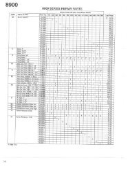
MENU DEFAULT VAL. RANGE DESCRIPTION<br />
BOILERS<br />
# of Boilers 1 (1-16) if operating as a member or in relay mode.<br />
Dynamic<br />
Up to 16 auto-detected boilers: master mode<br />
LEAD STAGE # 1 (1-16) # of first boiler to run, determines the fire order in rotation.<br />
HEAT BAND 30 ° F (10-50F) differential temp around setpoint used to stage boiler(s) OFF/ON<br />
SETPOINTS<br />
LOCAL SETPT 160 ° F (40-220F) Local setpoint used to maintain temperature of SETPT SOURCE<br />
OPERATE LIMIT 215 ° F (45-230F) When running as a member, boiler shuts off when reached<br />
Boiler restarts at lower temp of OP LIM BAND or 10F whichever is<br />
lower<br />
OP LIM BAND 20 ° F (1-50F) Limits external input % when in (OP LIM - OP LIM BAND)<br />
SETPT SOURCE SUPPLY (40-100F) if functioning as a Member, HEADER if functioning as Master<br />
OUTDOOR AIR RESET<br />
OA RESET OFF Outdoor reset ratio (boiler water temp/outside air temp)<br />
OA SETPOINT 68 ° F (40 - 100F) Temperature at which boiler shuts down, operation is below<br />
OVERRIDE RESET NO if boiler is running using the OA RESET, OA OVR input closed<br />
overrides and runs at local setpoint until OA OVR input opens<br />
WATER TEMP 140 ° F (60 - 150F) Boiler water temp setpoint when OA temp is at HIGH OATEMP<br />
At<br />
These four setpoints determine the OA reset slope.<br />
HIGH OA TEMP 70 ° F (50 - 90F)<br />
WATER TEMP 180 ° F (70 - 220F) Header/Supply setpoint when OA Temp is at LOW OA TEMP<br />
At<br />
LOW OA TEMP 10 ° F (-35 - 40F)<br />
PUMP OPTIONS<br />
DELTA TEMP ENAB OFF When enabled, use Delta temp to shut pump off when temp<br />
across boiler is less than DELTA TEMP .<br />
DELTA TEMP 10° F (2 - 50F)<br />
POST PRGE TIME 120 secs (60– 255s) Time in seconds to keep circ.pump on after boiler stops<br />
ALWAYS ENABLED OFF Pump never shuts off.<br />
NIGHT SETBACK<br />
SETBACK ENTRY 1 (1 – 4) Four setbacks to adjust setpoint during a time period<br />
ENTRY IS OFF Enable or disable the use of this setback<br />
SETBACK 20° F (0 – 50 F) temporarily subtracts this temp from the setpoint<br />
START DAY MON Day of the week to begin setback or a day range<br />
TIME 12:00AM Time to begin setback<br />
END DAY MON Day of the week to end the setback or a day range<br />
TIME 12:00AM Time of the day to end the setback<br />
OPTIONS<br />
TEMP SCALE ° F (F or C) Fahrenheit scale is default<br />
KEY CLICK ON Beeps when a key is pressed<br />
SKIP PASSWORD ON Disables the Password<br />
BRIGHTNESS 50% (12,25,37, Display brightness, lower for longer life<br />
50,62,75,87,100)<br />
DATA LOG<br />
DATA LOG (1 – 1000) Displays the Number of entries in data log and current entry<br />
Page 17
REV 1.1<br />
<strong>FIII</strong> <strong>SERIES</strong> <strong>CONTROL</strong><br />
AUX FUNCTIONS<br />
COMBUST AIR DAMPER<br />
IN USE? NO If set to YES, then OUTPUT RELAY # can be used<br />
to control a <strong>com</strong>bustion air damper.<br />
OUTPUT RELAY # K5 If K5 is used, There can be no Boiler #3 as a member<br />
address, since the onboard relay is shared by boiler #3<br />
and with the <strong>com</strong>bustion air damper function.<br />
PROOF TIME 2:00 (0 – 4min) This is the proving time in minutes for the<br />
<strong>com</strong>bustion air proof switch. It is sensed at SPARE 1<br />
on J10B. Also Sensor #5 must be set to ON/OFF in<br />
the sensors menu in order to detect the prove switch<br />
being made. If a fault occurs, remove the call for heat to clear.<br />
ALARM SILENCE<br />
IN USE? YES This menu allows the configuration of the Alarm Silence switch.<br />
It can be disabled so that the Alarm Silence switch can not silence<br />
the alarm until the alarm is cleared; ALARM SILENCE = NO. The<br />
default value is to enable the ALARM SILENCE switch.<br />
INPUT = J10B SPARE 2 This setting allows the Alarm Switch to be looked at using another<br />
input. This input should not be changed, but allows for custom<br />
configurations to resolve conflicts.<br />
HEAT EXCHANGER<br />
ALARM TYPE: WARNING This setting determines the way in which the control reacts when the<br />
differential temperature across the heat exchanger exceeds the<br />
specified maximum differential temperature. The default alarm<br />
condition is a WARNING. The WARNING state will allow the<br />
boiler to keep functioning and display a warning message and a<br />
timestamp in the status screen when the maximum differential<br />
temperature is exceeded. If FAULT is selected, the boiler will shut<br />
down and act as if an interlock has tripped.<br />
EXCHR DELTA T 45F per Boiler This is the maximum differential temperature the heat exchanger can<br />
see before the ALARM TYPE is applied. This value can not be<br />
changed and is defined for each boiler size.<br />
LIM-> HALF RATE YES Limit to Half Rate: When set to YES, and the maximum differential<br />
temperature (delta T) has been exceeded, the fire rate called for is cut<br />
in half. In other words: if we are calling for 80% modulation and<br />
have exceeded the delta T, the boiler will only fire at 40%. The delta<br />
T needs to drop 10F below the maximum delta T to reset this<br />
limit. This method helps protect the heat exchanger from damage<br />
due to excessive delta T’s.<br />
SYSTEM CLOCK<br />
TIME<br />
This time needs to be entered at first turn-on and in<br />
DAY OF WEEK the event that power has been lost for more than 3<br />
MONTH<br />
days. The time is only required for an accurate log<br />
DAY<br />
entry time-stamp and fault time stamp.<br />
YEAR<br />
PRESS SEL TO SAVE<br />
The SEL key must be pressed after all time values<br />
have been entered to save all time values at once.<br />
DISTRIBUTED CTRL<br />
<strong>CONTROL</strong> H-Net Two methods of operation: RELAY & H-Net<br />
H-Net MASTER YES Auto detected, based on the HEADER sensor. If the<br />
HEADER sensor is present and is set to TYPEZ or<br />
TE6000, the <strong>FIII</strong>-series control is run as a H-Net<br />
MASTER (YES). If the HEADER sensor is not<br />
TYPEZ or TE6000, H-Net MASTER = NO.<br />
Page 18
REV 1.1<br />
<strong>FIII</strong> <strong>SERIES</strong> <strong>CONTROL</strong><br />
LOCAL ADDRESS 255 (2 –16) The local address is the address of a member device.<br />
This is normally in the range of 2 through 16. But if<br />
the <strong>FIII</strong>-series control is a MASTER, then the<br />
default address is 255. The LOCAL ADDRESS # is<br />
synonymous with boiler #.<br />
CONSOLE ADDRESS 1 (1 – 247) The console address is for <strong>com</strong>municating with<br />
Laptop, PC, or other MODBUS capable device. It is<br />
the 2 nd <strong>com</strong>munication port reserved for a host<br />
control.<br />
MODULAR BOILER SET<br />
ADD BOILER DELAY 10mins (0 – 15min) This is the delay time in 30sec intervals, before starting a new<br />
boiler. Boiler #1 is started immediately after a call for heat.<br />
If a second boiler needs to start, the ADD BOILER<br />
DELAY will need to expire before starting.<br />
SHED BOILER DELAY 2mins (0-15min) This is the delay time in 30 second intervals, before stopping a boiler.<br />
MODULATE DELAY TIME 10 secs (0 – 60min)<br />
This is the time the boiler remains in min-fire before it relinquishes<br />
control to the modulation % signal.<br />
MOD MAX – LAST FIRE 80% (25 – 100%) This is the “INPUT CLAMP” message displayed in the STATUS<br />
screen when an ‘*’ is displayed. This value represents the % of<br />
output on all boilers if the last boiler is not firing. Once the last<br />
boiler fires, this clamp is removed and all boilers are allowed to<br />
modulate up to 100%. This value is derived by (Maximum fire rate<br />
of a boiler – Minimum fire rate of a boiler). In mixed boiler size<br />
configurations, more than (2) boilers in a system, or when “bumps”<br />
in the temperature occur as boilers are added and subtracted, this<br />
value may need adjustment. The adjustments will help produce<br />
smooth temperature control when each boiler is started and stopped.<br />
This method ensures that, once a new boiler starts to fire, and holds<br />
its fire rate at the minimum setting, it does not add its BTU output to<br />
a boiler already firing at 100%. The boilers can’ t be fired starting @<br />
0%, but start at a minimum (example: 20%) and introduce a<br />
minimum amount of BTUs into the system.<br />
STOP BAND OFFSET 5° F (0 - 50F) The value used to prevent short cycling when in the temperature<br />
control band. If a boiler was just added and has not finished its<br />
modulation delay period and is within 5° F of the top of the band,<br />
the boiler will stop early.<br />
BOILER START TIME 50 secs (0 –4min) The time it takes from when a call-for-heat is received to the time the<br />
boiler begins its modulation delay (running at min fire). It is required<br />
to predict starting the boiler early and when starting the last boiler<br />
when the input clamp is in effect.<br />
MODULATION PID<br />
(P) ROPORTIONAL 100 (0 – 100) Proportion constant<br />
(I)NTEGRAL 10 (0 – 100) Integral constant<br />
(D)ERIVATIVE 10 (0 – 100) Derivative constant<br />
BAND 100° F (40 – 200F) Temperature band that is used much like the proportional band<br />
FIRING MODE<br />
LAST ON FIRST OFF LOFO Used to provide firing rotation of the boilers for<br />
FIRST ON FIRST OFF FOFO equalizing run times.<br />
SENSORS<br />
SENSOR #<br />
NOTE: sensors can only be changed with no-call-for-heat<br />
The first (4) sensor #’s are reserved as: OUTSIDE AIR, water<br />
SUPPLY outlet, water RETURN inlet, and system HEADER<br />
Page 19
REV 1.1<br />
<strong>FIII</strong> <strong>SERIES</strong> <strong>CONTROL</strong><br />
TYPE<br />
CALIBRATE<br />
temperature. If the HEADER sensor is used (TYPEZ), that boiler<br />
performs the tasks of the MASTER boiler. If the HEADER sensor is<br />
set to NONE, its function is the MEMBER. The remaining (2)<br />
sensors perform as user selections and provide functions such as:<br />
Combustion Air Proving.<br />
There are (4) sensor types:<br />
NONE = don not use this sensor<br />
TYPEZ = 10k thermistor<br />
TE6000 = 1k Nickel RTD<br />
ON/OFF = 5 volts supplied out to detect a contact/switch closure.<br />
Placing a precision 10k (TYPEZ) or 1k (TE6000) precision resistor<br />
across the sensor input selected allows calibration of the sensor input.<br />
PASSWORD AAAAAA Provides a limited access for security, though restoring system<br />
defaults will reset the password to the value “AAAAAA”<br />
COMMUNICATIONS<br />
MODEM INSTALLED NO Modem support is not available currently with this release.<br />
LOAD DEFAULTS<br />
FACTORY CAL?<br />
Selecting YES will load just the factory calibration values: MIN,<br />
MAX and IGNITION.<br />
FACTORY RESET? NO Selecting YES will load all factory defaults except the Calibration<br />
values.<br />
SYSTEM<br />
FACTORY TEST<br />
Used by factory to check analog and binary inputs.<br />
LOAD FIRMWARE NO Answering YES deletes the Firmware and allows a firmware<br />
update.<br />
APPLICATION HEAT This is the type of heating application that this boiler will perform.<br />
If the boiler is to be used for heating of a building, HEAT is<br />
selected. If it is to be used to heat domestic hot water DHW, select<br />
DHW. The result of setting is so that HEAT or DHW will produce<br />
the correct display terms. These can be observed when cycling<br />
through menus or viewing temperatures on the status screens.<br />
Page 20
REV 1.1<br />
<strong>FIII</strong> <strong>SERIES</strong> <strong>CONTROL</strong><br />
MODBUS Communications<br />
The <strong>FIII</strong>-series control can be controlled using Modbus <strong>com</strong>mands to Enable/Disable the boiler/system. A connection to the<br />
Console Modbus Port on the Communications board is required. The Master Boiler assumes the role of MEMBER, RTU,<br />
192Kb, 8 bits, Even Parity, 1 stop bit, when connected to a BMS (Building Management System).<br />
The Member Boilers should not be connected to a BMS system other than to view Read Only addresses.<br />
Modbus Holding (Read/Write) Registers<br />
Address Data Type Description Valid Values/Range<br />
0 Unsigned Boiler/System Enable/Disable 0 = Disabled/Off<br />
1 = Enabled/On<br />
1 Unsigned System Setpoint Timer (1) 0 – 65535 seconds<br />
2 Unsigned System Setpoint (1) 40°F – 220 °F<br />
3 Unsigned Outdoor Air Reset Enable/Disable 0 = Disabled/Off<br />
1 = Enabled/On<br />
4 Unsigned Outdoor Air Setpoint 40°F - 100 °F<br />
5 Unsigned Water Temperature at High Outside Air 60°F - 150 °F<br />
6 Unsigned High Outside Air Temperature 50°F - 90 °F<br />
7 Unsigned Water Temperature at Low Outside Air 70°F - 220 °F<br />
8 Signed Low Outside Air Temperature -35°F - 40 °F<br />
9 Unsigned Set Clock – Month (2) 0 – 11<br />
10 Unsigned Set Clock – Day of Month (2) 1 – 31<br />
11 Unsigned Set Clock – Year (2) 0 – 99<br />
12 Unsigned Set Clock – Hours (2) 0 – 23<br />
13 Unsigned Set Clock – Minutes (2) 0 – 59<br />
14 Unsigned Set Clock – Seconds (2) 0 – 59<br />
15 Unsigned Set Clock – Day of Week (2) 1 – Monday<br />
7 – Sunday<br />
16 Unsigned Set Clock – After the Set Clock Registers listed above<br />
have been written, a 1 must be written to this location<br />
to set the clock. (2) 1<br />
(1) The system setpoint timer and system setpoint work in tandem to externally control (i.e. a BMS - building<br />
management system) the operating setpoint. The setpoint (countdown) timer should be loaded with a timeout value (in<br />
seconds) prior to writing the system setpoint. When the timer reaches zero, the control assumes that the BMS is no<br />
longer operating and the local setpoint (saved on the control) is reloaded. This is a failsafe feature used to help<br />
safeguard the system in case of BMS failure. If the setpoint timer is not written, a default timeout value of 60 seconds<br />
is assumed.<br />
(2) To write the system clock, registers 9 – 15 must first be loaded with the correct date and time. Then, a 1 must be<br />
written to register 16 to write the date and time to the system clock.<br />
Page 21
REV 1.1<br />
<strong>FIII</strong> <strong>SERIES</strong> <strong>CONTROL</strong><br />
Modbus Input (Read Only) Registers<br />
Address Data Type Description Valid Values/Range<br />
0 Unsigned Boilers Running 0 – 16<br />
1 Modulation (% BTU Load) 0 – 100<br />
2 Header / System Temperature 32 – 250 °F<br />
3 Supply Temperature 32 – 250 °F<br />
4 Return Temperature 32 – 250 °F<br />
5 Outside Air Temperature -40 – 250 °F<br />
6 Signed Spare Input 1 -32768 to 32767<br />
7 Signed Spare Input 2 -32768 to 32767<br />
8 Unsigned Clock – Month 0 – 11<br />
9 Unsigned Clock – Day 1 – 31<br />
10 Unsigned Clock – Year 0 – 99<br />
11 Unsigned Clock – Hours 0 – 23<br />
12 Unsigned Clock – Minutes 0 – 59<br />
13 Unsigned Clock – Seconds 0 – 59<br />
14 Unsigned Clock – Day of Week 1 – Monday<br />
7 – Sunday<br />
15 – 46 Unsigned Boilers 1 – 16 status flag (32-bit) registers. The upper<br />
16-bits of each 32-bit register is stored at odd<br />
numbered addresses 15 – 45. The lower 16-bits of each<br />
32-bit register is stored at even numbered addresses 16<br />
– 46.<br />
See the Boiler Status<br />
Flags Table Below<br />
47 – 78 Unsigned Boilers 1 – 16 runtime (32-bit) registers. The upper<br />
16-bits of each 32-bit register is stored at odd<br />
numbered addresses 47 – 77. The lower 16-bits of each<br />
32-bit register is stored at even numbered addresses 48<br />
– 78.<br />
0 – 4294967295<br />
seconds<br />
When the upper and lower registers are <strong>com</strong>bined they<br />
form a 32-bit unsigned integer that is the number of<br />
seconds that the boiler has been running. For instance:<br />
(((Register 29) * 65536) + Register 30) = Boiler 1<br />
runtime in seconds.<br />
Boiler 1 is the master boiler. Boilers 2 – 16 are<br />
member boilers.<br />
Page 22
REV 1.1<br />
<strong>FIII</strong> <strong>SERIES</strong> <strong>CONTROL</strong><br />
Boiler Status Flags<br />
Bit Description Bit Description<br />
0 Disabled 16 Ignition Alarm<br />
1 Local Override 17 Valve Alarm<br />
2 Alarm 18 High Limit<br />
3 Failed 19 Air Prove Switch<br />
4 Member Error 20 XS Factory<br />
5 Boiler Running 21 Software Operator<br />
6 Pump Running 22 ---<br />
7 Spare 3 Interlock 23 ---<br />
8 LWCO Interlock 24 ---<br />
9 VFD Interlock 25 ---<br />
10 Operator Interlock 26 ---<br />
11 Water Prove (Flow) Interlock 27 ---<br />
12 Air Prove UV Sensor Interlock 28 ---<br />
13 Main Valve 29 ---<br />
14 Pilot Valve 30 ---<br />
15 Main Valve 31 Present (Boiler Detected)<br />
Page 23
REV 1.1<br />
<strong>FIII</strong> <strong>SERIES</strong> <strong>CONTROL</strong><br />
Troubleshooting<br />
Situation: Nothing happens when the power switch is turned on.<br />
1. Check For 120/240 VAC on the Service connector J1. Verify the line power is connected as per wiring diagram. The<br />
Power switch light (ON - Position) should illuminate if this is wired correctly. If the light does not illuminate on the<br />
power switch, ensure that J7 is connected to the main board and the power switch.<br />
2. If the Ignition Control is active, but the front panel display is inactive check:<br />
A. Cable and cable polarity from the control board to the display.<br />
B. J14 on control board. 120vac is routed from here to the transformer. The transformer returns 24vac to power<br />
the control.<br />
C. Check for 120vac on the primary of the transformer and 24vac on the secondary. If one of the 24vac interlocks<br />
has been shorted to ground or the 24vac output is low, the transformer may be damaged or a 24vac circuit may<br />
be miss-wired.<br />
NOTE: The <strong>FIII</strong>-series control is equipped with resettable fuses on the power input circuit. Wiring power<br />
incorrectly to the unit will cause these fuses to open. Once the incorrect wiring is corrected, the fuses should reset<br />
themselves in less than 5 minutes.<br />
Situation: You get the error message for the Combustion Air Damper.<br />
1. The prove switch for the <strong>com</strong>bustion air damper is not closing. Check to make sure the dampers are being controlled<br />
by the output relay you specified when programming for the damper. Also check to make sure the prove switch is<br />
working properly.<br />
2. If there is no prove switch, you must put a jumper wire across input connection: SPARE 1.<br />
3. If (2.) has been done and you continue to get the error message, check the sensor TYPE specified for sensor #5 in the<br />
sensors menu. If it is set to NONE the controller will not recognize the closed circuit. Set the Sensor #5 to ON/OFF.<br />
4. If you are not using the <strong>com</strong>bustion air damper then it needs to be disabled in the AUX FUNCTIONS menu.<br />
Situation: The display is displaying random characters or the control keeps resetting.<br />
There may exist a grounding problem with the controller or one of the boilers, pumps, contactors or other devices connected<br />
to it. If all grounding is correct, there may be an issue with radiated or induced electrical noise (interference). This may be<br />
caused by, arcing across a contactor's contacts when starting a pump motor, or a large electrical load. It may also be caused<br />
by, the ignition transformer being improperly grounded, or the spark gap set incorrectly.<br />
Attempt to identify the noise source:<br />
1. What is the boiler/controller trying to do at the time of the failure?<br />
2. Is the boiler on the same circuit as the noise source? (the boiler should have isolated power.)<br />
3. Are shielded sensor wires used? (Ensure the shields are grounded only at the boiler control end.)<br />
4. Are any sensors or sensor wires located near a transmitting antenna? (Move sensor)<br />
Situation: There are no heating boilers on.<br />
1. Check the settings for OA SETPOINT and OA RESET; if the outdoor air temperature is above the OA<br />
SETPOINT and OA RESET is on, the circulator pump relay will be locked out and the heating boilers will not<br />
fire.<br />
2. If the water temperature is within the heating band around the setpoint, boilers will not <strong>com</strong>e on. The water<br />
temperature must fall below the lower band limit to begin firing boilers.<br />
Situation: Unable to change the # of Boilers in the BOILERS menu.<br />
1. In RELAY method, ensure that the controller does not have any call-for-heat (none of the control inputs are<br />
made). The number of boilers can’t be changed when operating the <strong>FIII</strong>-series control with a call-for-heat.<br />
2. In H-Net method, the <strong>FIII</strong>-series control auto-detects the boilers in the system and adjusts the # of boilers<br />
accordingly. The # of boilers can be manually set only when operating in RELAY method.<br />
3. In H-Net method, if the # of Boilers is not being adjusted properly to the actual amount of boilers in the system,<br />
check each boiler. There can only be (1) master boiler, but there can be up to 15 member boilers. Currently, a<br />
total of 16 boilers in a system is allowed when not using a <strong>com</strong>bustion air damper. If a <strong>com</strong>bustion air damper is<br />
used, boiler #3 is not allowed as a member, since the relay on board controls the damper and boiler 3. This<br />
limits the system to a total of 15 boilers.<br />
Page 24
REV 1.1<br />
<strong>FIII</strong> <strong>SERIES</strong> <strong>CONTROL</strong><br />
Situation: You get the error message – WATER FLOW SWITCH or WAITING FOR FLOW.<br />
1. If the control does not sense a closed circuit at input connection, WTR FLW. Check to make sure the circuit for the<br />
circulator pump is correct, that the pump is being energized, and that the flow prove switch is working properly.<br />
2. If there is no flow prove switch, check to make sure that a jumper wire has been hooked up to J11B, WTR FLW<br />
interlock.<br />
Situation: H-Net boilers are detected but then lost and then detected again etc...<br />
1. The H-Net <strong>com</strong>munications cable may be receiving interference from the blower, ignition, or other form of radiated<br />
electrical noise. Termination of the jumpers may not be correct or there is more than one master.<br />
A. Ensure that the termination jumpers are set on the MASTER boiler and only the LAST MEMBER boiler.<br />
All of the other member boilers should have their termination jumpers in the non-terminated position.<br />
B. There may be (2) or more MASTER boilers. Ensure that only one header sensor is present and connected to<br />
the SYS/DHW input. There should be no wires or sensors connected to the SYS/DHW input if the boiler is<br />
operating as a member. This input is auto detected and defines the boiler as a MASTER.<br />
C. Ensure the cable to connect the H-Net is of a shielded or twisted pair type. Shielding of the cable is<br />
required.<br />
D. Minimize the electrical interference by routing the <strong>com</strong>munications cable away from electrical noise<br />
sources, such as: Motors, ignition controls, contactors etc…<br />
Situation: Only the MASTER boiler Fires, but the system has many boilers and is using H-Net.<br />
1. In order for the MASTER boiler to act as a MASTER, the header sensor must be set to TYPEZ or TE6000, and there<br />
must be a header sensor present. At power-up, the header sensor is auto detected. If the temperature of the header<br />
sensor at power-up is greater than –25 F and less than 240 F it is considered a valid sensor. The boiler will default to<br />
the MEMBER mode if the temperature is not in this range and can only be run locally or by external inputs.<br />
2. If the LOAD FACTORY DEFAULTS has been used to restore all the default settings, the header sensor<br />
has been set to NONE. This needs to be set as stated in 1, and the header sensor will need to be replaced or<br />
the temperature brought into a valid range. A power cycle of the boiler will detect the sensor if it is in the<br />
range as stated in 1.).<br />
3. The H-Net needs a <strong>com</strong>munications cable daisy-chained between boilers. Ensure that a good connection is<br />
made on the <strong>com</strong>munications board and that the lights on the dual RJ45 jack flash (roughly twice a second).<br />
The MASTER is the only one that should flash with no <strong>com</strong>munications cables plugged in.<br />
Situation: I am in CALIBRATE and I cannot fire the boiler to adjust it.<br />
1. Only one, but any one of the T1-T4 inputs can be used to start the boiler. All other inputs are disabled. This method<br />
prevents an external control or Building Management System from trying to control the boiler while it is offline and<br />
being calibrated. If the boiler is being used as a staged boiler controlled by an external control, the staged inputs need<br />
to be disconnected before CALIBRATION, since more than one of the T inputs may be closed by the external control.<br />
Situation: You have forgotten the password.<br />
As a last resort, you can turn the controller off, then depress and hold the ESC key while turning it back on. This will load<br />
the default password “AAAAAA”.<br />
Situation: Firmware update program starts to load, but then stops.<br />
1. Check that the termination resistors J3 and J6 are not in the termination setting. If they are, remove them temporarily<br />
while updating. Restore them for proper <strong>com</strong>munication with a building management system.<br />
Page 25
REV 1.1<br />
<strong>FIII</strong> <strong>SERIES</strong> <strong>CONTROL</strong><br />
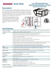
4-20 ma signal<br />
Once boiler starts the<br />
control signal m ust<br />
drop below 4.01 m a<br />
to stop Boiler<br />
0ma<br />
4ma<br />
A control signal<br />
greater tha 4m a will<br />
start boiler.<br />
20ma<br />
NO EFFECT<br />
Output Range From<br />
Control<br />
Control Signal<br />
Display input % of control when running<br />
0% 100%<br />
Percent of Boilers<br />
INPUT<br />
Boiler OFF<br />
Control Signal to MAX Output<br />
M AX<br />
OUTPUT<br />
0%<br />
Boiler OFF<br />
25% 100%<br />
Boiler Output<br />
Percent of Boilers<br />
OUTPUT<br />
0%<br />
BLOW ER OFF<br />
20% = the<br />
m inim um speed<br />
the VFD will run<br />
20%<br />
80% 100%<br />
BLOW ER FULLY<br />
ON<br />
PW M DUTY CYCLE<br />
0%<br />
Boiler OFF<br />
25% IGNITION<br />
100%<br />
Percent of Boilers<br />
Output<br />
IGNITION<br />
After<br />
Ignition<br />
Page 26
REV 1.1<br />
<strong>FIII</strong> <strong>SERIES</strong> <strong>CONTROL</strong><br />
Page 27
REV 1.1<br />
<strong>FIII</strong> <strong>SERIES</strong> <strong>CONTROL</strong><br />
<strong>FIII</strong> <strong>SERIES</strong> RUN SCREEN<br />
Hold theBACK<br />
button down<br />
for 5 seconds<br />
to enter the<br />
SETUP menus<br />
RUN %100 SYSTEM SET<br />
140°F<br />
RUN %100 HEADER<br />
150°F<br />
RUN %100 SUPPLY<br />
118°F<br />
Press the UP or Down Arrow<br />
Keys to navigate the display<br />
screen.<br />
The SETPOINT can be<br />
adjusted by pressing and<br />
holding the SELECT button<br />
until the SETPOINT flashes.<br />
Then use the UP and DOWN<br />
buttons to change the value.<br />
Prssing the SELECT button<br />
saves the value.<br />
CALIBRATE<br />
RUN %100 OUTSIDE<br />
52°F<br />
RUN %100<br />
MINIMUM<br />
CALIBRATE<br />
25%<br />
RUN %100<br />
RETURN<br />
RUN %100<br />
IGNITION<br />
CALIBRATE<br />
90°F<br />
30%<br />
RUN %100<br />
*STATUS<br />
START 0<br />
STOP 0<br />
RUN %100<br />
MAX OUTPUT<br />
CALIBRATE<br />
90%<br />
RUN %100<br />
BLRS FIRING<br />
RUN %100<br />
PID<br />
1_2______<br />
_________<br />
RUN %100<br />
DELTA TEMP<br />
RUN %100<br />
DELTA TEMP<br />
CALIBRATE<br />
25°F<br />
25°F<br />
Page 28
REV 1.1<br />
<strong>FIII</strong> <strong>SERIES</strong> <strong>CONTROL</strong><br />
<strong>FIII</strong> <strong>SERIES</strong> MENU TREE<br />
HOME SCREEN<br />
RUN %100<br />
SYSTEM SET<br />
140°F<br />
Press and HOLD BACK<br />
button down for 5<br />
seconds to enter the<br />
menu screen<br />
MAIN MENU SCREEN<br />
SETUP<br />
ADVANCED SETUP<br />
VI EW LOG<br />
FUTERA I I I<br />
BOI L ERS<br />
SETPOI NTS<br />
OUTDOOR<br />
A I R<br />
V 1 . 0<br />
RESET<br />
ADVANCED MENUS<br />
# OF BO I LERS 1<br />
LEAD BOI LER # 1<br />
HEAT BAND 4 0 °F<br />
HLK 1 2<br />
3 : 0 5 : 4 2 P 1 0 / 1 4 1 3<br />
H2O 1 2 7 °F SET 1 4 0 °F<br />
OA 6 5 °F MOD% 5 7<br />
1 - - - - - - P MPBH HD<br />
LOCAL SET<br />
OPERATE L I M °<br />
OP L IM BAND<br />
SETPT SOURCE HEADER<br />
OA RESET OFF<br />
OA SETPOI NT °F<br />
OVERRIDE RESET ON<br />
SET OA SETPOI NTS<br />
NEXT<br />
BACK<br />
PUMP OPT I ONS<br />
NIGHT SETBACK<br />
OPTIONS<br />
DATA LOG<br />
DELTA TEMP ENAB OFF<br />
DELTA TEMP 10°<br />
POST PRGE T I ME<br />
120s<br />
ALWAYS ENABLED OFF<br />
NI GHT SETBACK<br />
TEMP SCALE F<br />
KEY CL I CK ON<br />
SKI P PASSWORD ON<br />
BRI GHTNESS 50%<br />
DATA LOG<br />
AUX FUNCT I ONS<br />
SYSTEM CLOCK<br />
DATA LOG ENTRY 214<br />
S I ZE 214<br />
COMBUST A I R DAMPER<br />
ALARM S I LENCE<br />
HEAT EXCHANGER<br />
Page 29
REV 1.1<br />
<strong>FIII</strong> <strong>SERIES</strong> <strong>CONTROL</strong><br />
ADVANCED MENUS<br />
DISTRIBUTED CTRL<br />
MODULAR BOI LER SET<br />
MODULATI ON PI D<br />
F IRI NG MODE<br />
<strong>CONTROL</strong> H- NET<br />
H- NET MASTER YES<br />
LOCAL ADDRESS 255<br />
CONSOLE ADDRESS 1<br />
ADD BOI<br />
LER DELAY<br />
SHED BOILER<br />
DELAY<br />
MODULATE DELAY TI ME<br />
MOD MAX - LAST FIRE<br />
( P)<br />
ROPORT IONAL<br />
)<br />
( I %100<br />
( NTEGRAL<br />
D) ERI VATI VE<br />
BAND GA I N<br />
FI RI NG MODE<br />
SENSORS<br />
PASSWORD<br />
COMMUNICATI ONS<br />
F I RI NG MODE<br />
LAST ON F I RST<br />
CAL I BRATE?<br />
OFF<br />
NO<br />
PLACE A PRECI SI ON<br />
1K OR 1OK RESI STOR<br />
ON CHANNEL # __<br />
TRI M OHMS = ___<br />
PASSWORD<br />
COMMUNICATIONS<br />
SYSTEM LOAD DEFAULTS<br />
CHA<br />
NG<br />
PASSW OR<br />
D<br />
O L D: - - - - - -<br />
EW: - - - - - -<br />
COMMUNICATI ONS<br />
MODEM I NSTALLED<br />
TRI M VALUE SET!<br />
FACTORY TEST<br />
LOAD FI RMWARE<br />
APPL I CAT I ON HEAT<br />
FACTORY<br />
FACTORY<br />
CAL?<br />
RESET?<br />
NO<br />
NO<br />
Page 30
REV 1.1<br />
<strong>FIII</strong> <strong>SERIES</strong> <strong>CONTROL</strong><br />
Worksheet<br />
SETUP MENU<br />
BOILERS<br />
# of BOILERS<br />
LEAD STAGE<br />
HEAT BAND °<br />
SETPOINTS<br />
LOCAL SETPOINT °<br />
OPERATE LIMIT °<br />
OP LIM BAND °<br />
SETPOINT SOURCE<br />
OUTDOOR AIR RESET °<br />
OA RESET<br />
OA SETPOINT °<br />
OVERRIDE RESET<br />
SET OA SETPOINTS<br />
WATER TEMP °<br />
@<br />
HIGH OA TEMP °<br />
WATER TEMP °<br />
@<br />
LOW OA TEMP °<br />
PUMP OPTIONS<br />
DELTA TEMP ENAB<br />
DELTA TEMP °<br />
POST PRGE TIME<br />
s<br />
ALWAYS ENABLED<br />
NIGHT SETBACK<br />
SETBACK ENTRY 1 2 3 4<br />
ENTRY IS<br />
SETBACK ° ° ° °<br />
SETBACK TIME<br />
START DAY<br />
TIME<br />
END DAY<br />
TIME<br />
OPTIONS<br />
TEMP SCALE °<br />
KEY CLICK<br />
SKIP PASSWORD<br />
BRIGHTNESS %<br />
CLEAR DATA LOG<br />
AUX FUNCTIONS<br />
COMBUST AIR DAMPER<br />
Page 31
REV 1.1<br />
<strong>FIII</strong> <strong>SERIES</strong> <strong>CONTROL</strong><br />
IN USE?<br />
OUTPUT RELAY #<br />
PROOF TIME<br />
SYSTEM CLOCK<br />
ADVANCED SETUP<br />
DISTRIBUTED CTRL<br />
<strong>CONTROL</strong><br />
H-Net MASTER<br />
LOCAL ADDRESS<br />
CONSOLE ADDRESS<br />
MODULAR BOILER SET<br />
ADD BOILER DELAY<br />
SHED BOILER DELAY<br />
MODULATE DELAY TIME<br />
MOD MAX – LAST FIRE %<br />
STOP BAND OFFSET °<br />
BOILER START TIME<br />
MODULATION PID<br />
(P)ROPORTIONAL =<br />
(I)NTEGRAL =<br />
(D)ERIVATIVE =<br />
BAND °<br />
FIRING MODE<br />
SENSORS<br />
SENSOR # OUTDSIDE SUPPLY RETURN HEADER 5 6 7 8<br />
TYPE<br />
PASSWORD<br />
COMMUNICATIONS<br />
MODEM INSTALLED<br />
LOAD DEFAULTS<br />
SYSTEM<br />
Page 32
REV 1.1<br />
<strong>FIII</strong> <strong>SERIES</strong> <strong>CONTROL</strong><br />
Thermistor Resistance/Temperature Table<br />
Temp °C Temp °F Resistance Temp °C Temp °F Resistance<br />
-40 -40 336,450 60 140 2,488<br />
-35 -31 242,660 65 149 2,083<br />
-30 -22 176,960 70 158 1,752<br />
-25 -13 130,410 75 167 1,479<br />
-20 -4 97,072 80 176 1,255<br />
-15 5 72,951 85 185 1,070<br />
-10 14 55,326 90 194 915.4<br />
-5 23 43,326 95 203 786.6<br />
0 32 32,650 100 212 678.6<br />
5 41 25,391 105 221 587.6<br />
10 50 19,899 110 230 510.6<br />
15 59 15,711 115 239 445.2<br />
20 68 12,492 120 248 389.6<br />
25 77 10,000 125 257 341.9<br />
30 86 8,057 130 266 301.0<br />
35 95 6,531 135 275 265.8<br />
40 104 5,326 140 284 235.4<br />
45 113 4,368 145 293 209.0<br />
50 122 3,602 150 302 186.1<br />
55 131 2,986<br />
Page 33
REV 1.1<br />
<strong>FIII</strong> <strong>SERIES</strong> <strong>CONTROL</strong><br />
260 N ELM STREET<br />
WESTFIELD, MA 01085<br />
(413)564-5515 FAX (413) 568-9613<br />
HydroTherm<br />
Page 34