
Create successful ePaper yourself
Turn your PDF publications into a flip-book with our unique Google optimized e-Paper software.
ISSUE 02/05<br />
15<br />
<strong>WICKES</strong> <strong>TIMBER</strong> <strong>DECKING</strong><br />
The use of timber to create<br />
garden features is probably<br />
one of the most popular<br />
changes people make to<br />
their gardens. Timber decks<br />
can be used in the same<br />
way as paving providing<br />
areas for tables and chairs<br />
on a firm base rather than<br />
on soft, perhaps soggy,<br />
ground.<br />
They can be built almost<br />
anywhere in the garden as<br />
areas for play or relaxation.<br />
They can be in the sun or<br />
shade and be built on level<br />
or sloping ground. They can<br />
be built on one or more<br />
levels, can have pergolas for<br />
climbing plants all over or<br />
part of the top and can have<br />
balustrading added on one<br />
or more sides.<br />
The decking system offered<br />
by Wickes is very flexible<br />
and can be used in many<br />
ways even being combined<br />
with traditional patio paving<br />
to create more unusual<br />
features.<br />
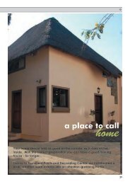
The component parts of the Wickes decking and pergola system are shown in the<br />
list below, and in this leaflet you will find a variety of ways in which they can be<br />
used. Provided that certain rules are followed our examples can be adapted to suit<br />
your needs.<br />
Product code Description QTY<br />
KEEP INFORMED<br />
• Look for other Good Idea<br />
Leaflets that could help you<br />
with your current project.<br />
• Check that your Good Idea<br />
Leaflets are kept up to date.<br />
Leaflets are regularly changed<br />
to reflect product changes so<br />
keep an eye on issue dates.<br />
• If you would like to be put on<br />
our mailing list for the Wickes<br />
booklet, call our Freephone<br />
number which is:<br />
0500 300 328<br />
•Visit our website at<br />
www.wickes.co.uk<br />
101-000 Deck Board 28 x 140 x 2400mm<br />
101-318 Stress Graded Joist 47 x 150 x 3000mm<br />
549-973 Deck Bearer/Pergola Upright 80 x 80 x 3000mm<br />
549-975 Pergola Cross Beam 40 x 90 x 2400mm<br />
549-974 Pergola Cross Beam 40 x 80 x 1800mm<br />
546-667 Newel Post 80 x 80 x 1200mm<br />
546-668 Handrail 2400mm<br />
546-666 Square Spindle 37 x 38 x 1064mm<br />
540-097 Shaped Spindle 36 x 36 x 812mm<br />
540-115 Deck 3 Tread Stair Stringer 855 x 525mm (D x H)<br />
600-615 Clear Wood Preserver 5L<br />
540-121 Decking Preserver 2.5L<br />
541-405 Landscaping Fabric 1 x 20m<br />
FIXINGS<br />
510-040 Exterior Screws No.8 x 65mm Pk150<br />
510-041 Coach Bolts M10 x 160mm<br />
510-042 160mm Exterior Coach Bolts Pk4<br />
510-043 Coach Bolts M10 x 130mm<br />
Main features of the softwood timber components are: -<br />
• Pre-treated for excellent resistance to rot and insect attack.<br />
• Fluted deck boards to help reduce slip and aid rainwater drain-off.<br />
• Decks and/or pergolas can be connected to a building or free standing.<br />
• Pergola components can be used to make archways or walkways.<br />
• Decks can be built off sloping ground<br />
With the components listed you can construct a number of garden features ranging
HANDRAIL<br />
DECK BEARER/PERGO-<br />
LA UPRIGHT<br />
ELEVATED DECKS. BUILT AS A SERIES OF<br />
PLATFORMS CONNECTED BY THE DECK<br />
STAIR RISER<br />
HANDRAIL<br />
DECK BOARD<br />
HANDRAIL<br />
STRESS GRADED<br />
JOIST<br />
POST<br />
NEWEL POST<br />
DECK STAIR RISER<br />
SQUARE<br />
SPINDLE<br />
DECK BOARD<br />
STRESS GRADED JOISTS ARE<br />
RECOMMENDED FOR USE WHEN<br />
CONSTRUCTING A RAISED DECK<br />
DECK BEARER<br />
BASIC TOOLS REQUIRED<br />
Spanners or Socket Set Handsaw Circular Saw or Jigsaw<br />
Drill and drill bits Cordless Drill/Driver Tape Measure<br />
String Line Spirit Level Hammer Wood Chisels<br />
Spade Screwdrivers Paint Brush Plumb Line Clamps<br />
SAFETY EQUIPMENT Dustmask RCD Adaptor<br />
Goggles/Protective Glasses Gloves<br />
A<br />
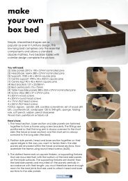
BASIC DECK-BOARD LAYOUT<br />
NOTE: AS THE BOARD<br />
LAYOUT DESIGN<br />
CHANGES SO WILL<br />
THE BEARER LAYOUT<br />
3040<br />
2400<br />
CHEVRON<br />
3040<br />
2400<br />
3040<br />
3040 3040<br />
2880<br />
Decking timbers, like any natural timber,<br />
can expand and contract depending<br />
upon ambient conditions. When you put<br />
them outside they may swell or, if the<br />
weather is very hot and dry, they will<br />
shrink. It is advisable, therefore, to<br />
purchase your timbers a week or so<br />
before you plan to construct your deck<br />
to allow the boards to adjust to the<br />
atmosphere. Store them close to where<br />
they will be used and ideally cover. Store<br />
them on level ground on timber bearers.<br />
All decking components are treated with<br />
a preservative treatment, however, when<br />
any of these are cut the cut surface<br />
must be treated with Wickes Decking<br />
Preserver to maintain the integrity of the<br />
treatment. Follow the instructions on the<br />
can, failure to treat correctly could affect<br />
your guarantee.<br />
SAFETY<br />
2400<br />
2400<br />
HORIZONTAL DIAGONAL BASIC DECK SUPPORT<br />
ALL DIMENSIONS IN mm BEARER LAYOUT<br />
from basic square or rectangular decks to<br />
decks on different levels with or without<br />
pergolas being added. In the remainder of<br />
this leaflet you will find a variety of options<br />
along with shopping lists and, where<br />
necessary, cutting and construction<br />
2400<br />
500<br />
details. For basic deck building only<br />
basic carpentry skills are required. More<br />
advanced projects do require greater<br />
planning and carpentry skills, but your<br />
level of skill will almost certainly improve<br />
as each project is completed.<br />
Take normal safety precautions when<br />
working with timber products. Wear<br />
gloves to avoid splinters and a nose and<br />
mouth mask when cutting to avoid the<br />
inhalation of dust. Always wear goggles<br />
when using circular saws, drills or<br />
sanders and always use an RCD device<br />
when using any power tools outside.<br />
You will collect timber offcuts which, if<br />
not used as deck strengtheners, may be<br />
stored for later use. Do not burn them<br />
and certainly do not use them as fuel for
B<br />
a barbecue. Remember that they are<br />
preservative treated.<br />
DECK PLANNING<br />
BEARER<br />
FRAME<br />
WORK<br />
DECK EDGE <strong>TIMBER</strong> SECURED IN<br />
PLACE, EITHER INTO THE DECK<br />
BOARD EDGE, PRIOR TO THE<br />
OTHER SIDE DECK BOARDS BEING<br />
FIXED,<br />
OR THROUGH THE TOP FACE<br />
DECK<br />
BOARDS<br />
BEARER<br />
FRAME<br />
WORK<br />
DECK<br />
BOARDS<br />
It is essential to plan your deck in<br />
advance and this is best done on paper.<br />
You cannot simply make up a bearer<br />
frame of any size and then expect the<br />
deck boards to fit with the required gaps<br />
between them without having to reduce<br />
the width of boards to fit.<br />
Carefully decide on the location and the<br />
use of your deck. Decide on whether<br />
you want a sunny or shaded location<br />
and importantly whether privacy is a<br />
requirement. Decks in permanent shade<br />
C<br />
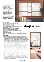
DESIGN LAYOUTS USING THE INDIVIDUAL MODULES SHOWN IN DIAGRAM D. OVERALL DIMENSIONS GIVEN IN mm<br />
3472<br />
3472 4630<br />
B<br />
C<br />
D<br />
D<br />
3472<br />
3472<br />
C<br />
E<br />
A<br />
C<br />
D<br />
E<br />
C<br />
A<br />
3472<br />
E<br />
E<br />
E<br />
E<br />
E<br />
E<br />
E<br />
B<br />
C<br />
E<br />
3472<br />
4630<br />
A<br />
E E<br />
E<br />
E<br />
E E<br />
E<br />
B<br />
C<br />
B<br />
C<br />
A<br />
E<br />
3472<br />
3472<br />
4630<br />
4630<br />
A<br />
B<br />
C<br />
D<br />
E<br />
D<br />
BOARD LAYOUT<br />
2315<br />
2315<br />
2315<br />
BEARER LAYOUT USING 80 x 80mm BEARERS<br />
2315<br />
MATERIALS LIST<br />
478<br />
7 3mBEARERS<br />
16 2.4m x 140mm DECK BOARDS<br />
160 No.8 X 65mm EXTERIOR WOODSCREWS<br />
20 150mm EXTERIOR NAILS<br />
1157<br />
1157<br />
ALL DIMENSIONS IN mm<br />
1157<br />
1157<br />
2315<br />
3274<br />
1157<br />
1636<br />
45°<br />
45°<br />
4 3mBEARERS<br />
8 2.4m x 140mm DECK BOARDS<br />
106 No.8 X 65mm EXTERIOR WOODSCREWS<br />
18 150mm EXTERIOR NAILS<br />
4 3mBEARERS<br />
8 2.4m x 140mm DECK BOARDS<br />
80 No.8 X 65mm EXTERIOR WOODSCREWS<br />
20 150mm EXTERIOR NAILS<br />
2 3mBEARERS<br />
4 2.4m x 140mm DECK BOARDS<br />
48 No.8 X 65mm EXTERIOR WOODSCREWS<br />
12 150mm EXTERIOR NAILS<br />
2 3mBEARERS<br />
2 2.4m x 140mm DECK BOARDS<br />
20 No.8 X 65mm EXTERIOR WOODSCREWS<br />
10 150mm EXTERIOR NAILS<br />
could be affected by damp and<br />
consequent algae growth. Listen to the<br />
views of your family and ensure that any<br />
decking feature is not too big for your<br />
garden. Be aware that very large decks<br />
and raised decks may require planning<br />
permission. Raised Decks should not<br />
be built with the deck level more than<br />
600mm above ground level without<br />
specialist advice. When installing posts<br />
or levelling take special care not to<br />
damaged underground pipes or drainage<br />
and do not obstruct manhole covers or<br />
other services.<br />
Diagram A shows a basic deck using<br />
boards and 80 x 80mm bearers with an<br />
overall size of 3040 x 2400mm. The<br />
layout of the bearers is shown and a<br />
shopping list is included. In this example<br />
the width of the deck is based upon the<br />
use of 21 uncut 2.4m long and 140mm<br />
wide deck boards with 20 gaps of 5mm<br />
between them. The calculation is: -<br />
21 x 140 = 2940<br />
20 x 5 = 100<br />
Total width = 3040mm
The base is designed to provide a<br />
complete perimeter with intermediate<br />
bearers at no more than 500mm<br />
spacings. The bearers are cut to length<br />
to suit the dimensions. Diagram A also<br />
shows how deck boards can be laid in a<br />
variety of ways. It is important that you<br />
plan your layout before assembling your<br />
bearers as the pattern will affect the<br />
spacing and number of bearers, e.g.<br />
double bearers will be needed for some<br />
chevron styles. See Diagram B.<br />
Plan your deck bearing in mind that it is<br />
the deck boarding that basically governs<br />
the size. For any deck you will need to<br />
work on the board widths at 140mm<br />
plus 5mm gaps in between.<br />
As a quick guide: -<br />
10 boards and 9 gaps<br />
= 1445mm deck width<br />
E<br />
F<br />
BEARER LAYOUT D<br />
G<br />
ENSURE ALL POSTS<br />
ARE SET VERTICALLY<br />
SUPPORT POST<br />
CONCRETE<br />
SETTING THE SUPPORT<br />
POST IN THE GROUND<br />
HALF A MEDIUM DENSI-<br />
TY CONCRETE BLOCK<br />
12 boards and 11 gaps<br />
= 1735mm deck width<br />
14 boards and 13 gaps<br />
= 2025mm deck width<br />
16 boards and 15 gaps<br />
= 2315mm deck width *<br />
18 boards and 17 gaps<br />
= 2605mm deck width<br />
20 boards and 19 gaps<br />
= 2895mm deck width<br />
* This is the key deck square, which has<br />
been sized to allow the other modules to<br />
interlink creating numerous deck<br />
designs.<br />
Designing such a deck to limit cutting<br />
and board or bearer wastage is difficult<br />
but not impossible. The art lies in<br />
constructing separate modules which<br />
link together in a number of ways. By<br />
DECK BEARER<br />
OFF CUT<br />
150mm NAILS<br />
150mm EXTERIOR NAILS DRI-<br />
VEN IN AT AN ANGLE SECUR-<br />
ING THE TWO MADE UP BEAR-<br />
ER LAYOUTS TOGETHER<br />
SLOPING SITE DECK<br />
BEARER LAYOUT E<br />
THE DECK SUPPORT<br />
FRAME IS SECURED TO<br />
THE POSTS WITH TWO<br />
150mm EXTERIOR NAILS<br />
using up to five different modules<br />
designed by Wickes a whole variety of<br />
deck designs and sizes can be built.<br />
If the site is sloping and it is not possible<br />
to level the ground you can still install a<br />
deck but part of it will have to be<br />
supported on timbers set into concrete<br />
in holes in the ground. A completely<br />
raised deck can also be installed using<br />
the same method but the deck level<br />
must not be more than 600mm above<br />
ground level. Do not build decks in very<br />
wet areas as constant contact with<br />
water could effect the life of the timber.<br />
Diagram C shows a number of deck<br />
designs using a combination of several<br />
modules with boards running in different<br />
directions for added interest. In all cases<br />
the bearer modules have been built as<br />
separate items and then connected in<br />
situ and then boarded out.<br />
Diagram D shows the construction of<br />
each module and lists the material<br />
requirements.<br />
Using diagram D you can draw out your<br />
own design and calculate your own<br />
material requirements.<br />
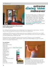
SITE PREPARATION<br />
Mark out the deck area using pegs and<br />
a string line following your plan drawing.<br />
If the ground is slightly uneven level it off<br />
and make sure that it is firm.<br />
If laying the deck over grassed or weedy<br />
areas we recommend that turves are<br />
removed then Wickes Landscaping<br />
Fabric is laid over the area to prevent<br />
future growth under the deck. If the<br />
ground is soggy or likely to become so<br />
in wet periods spread pea shingle over it<br />
to a depth of about 25mm. Your bearer<br />
frame will bed down onto the shingle<br />
and will, to a large extent, be kept off<br />
almost permanently wet ground.<br />
If you are constructing a deck on level<br />
ground further marking out is not<br />
normally required as bearers can be laid<br />
out in the positions that they will be<br />
used.<br />
BASIC BEARER FRAME ASSEMBLY<br />
WITH 80 x 80mm BEARERS<br />
Make the outer frame first, then mark, cut<br />
and fit the intermediate bearers<br />
remembering the maximum 500mm<br />
spacing limit. Treat every cut end with<br />
Wickes Decking Preserver. At each join<br />
use two 150mm exterior nails. As you<br />
proceed make sure that the frame remains<br />
flat and square. To check the squareness<br />
measure the frame diagonals. They must<br />
be equal.<br />
Make sure that the frame rests flat and is<br />
totally supported. If you find hollows under<br />
the frame or areas where it is held off the<br />
ground you may need to adjust the ground<br />
level to prevent the deck being ‘springy’.
H<br />
I<br />
K<br />
DECK BOARD<br />
MARK THE <strong>TIMBER</strong> USING A <strong>TIMBER</strong> BOARD<br />
OR STRINGLINE FROM A CENTRAL POINT<br />
AND USE A JIGSAW TO CAREFULLY CUT THE<br />
OVERHANGING DECKBOARDS<br />
USE A <strong>TIMBER</strong> STRIP TO<br />
ACT AS A GUIDE FOR A<br />
POWER SAW<br />
<strong>DECKING</strong><br />
THE DECK BOARDS ARE SECURED TO<br />
THE POSTS WITH No.8 x 65mm EXTERI-<br />
OR WOODSCREWS, TWO SCREWS PER<br />
BOARD AT EVERY BEARER<br />
BEARER<br />
J<br />
PENCIL<br />
MARKED<br />
CURVE<br />
Decking Boards can either be cut to the<br />
size of the frame or you can fit them<br />
over sized and trim down later.<br />
See Diagram I.<br />
Decks do not have to have hard straight<br />
edges. Curves can be created provided<br />
that the unsupported decking is not<br />
more than 150mm away from a bearer.<br />
Curves can be marked out with either a<br />
string line in an arc or with a piece of<br />
timber fixed to create an arc. See<br />
Diagram J.<br />
NOTE: Due to the timber width<br />
variations mentioned earlier you should<br />
not stick rigidly to fixing the first board,<br />
measuring or using a 5mm spacer then<br />
fixing the next board and so on. It is<br />
better to loose lay boards initially to<br />
determine what the gaps will actually<br />
need to be.<br />
The edge timber can be used to create<br />
the appearance of framing the deck<br />
boards. It is glued, nailed or screwed in<br />
position as required. The deck boards<br />
are cut to size and shape then fitted as<br />
previously described. The sequence for<br />
fitting the edging timber can vary<br />
depending on the design of your deck. It<br />
can be fitted prior to the deck boards,<br />
which are then cut to fit, or one side is<br />
boarded first, then edged, and then the<br />
other side is boarded. See Diagram B.<br />
You may wish to use the deck boards to<br />
edge around the perimeter of your deck,<br />
covering up the bearer frame wood.<br />
Diagram K.<br />
RAISED DECKS<br />
BEARER<br />
FRAMEWORK<br />
BEARER<br />
FRAMEWORK<br />
<strong>DECKING</strong><br />
If longer bearers are required these can<br />
be joined together by skew nailing<br />
offcuts, see Diagram E.<br />
The laying of a modular deck is<br />
essentially the same as for the basic<br />
deck. The only real difference is that<br />
each modular frame will be put in place,<br />
the next one added alongside and the<br />
two connected with 150mm exterior<br />
nails through the bearers at no more<br />
than 300mm centres. These nails should<br />
be driven in at an angle - skew nailed -<br />
as in Diagram F to make it more difficult<br />
for the timbers to pull apart.<br />
DECK BOARD<br />
DECK BOARD<br />
If the site is on a slight slope and it is<br />
not possible to level the ground you can<br />
still install a deck but part of it will have<br />
to be supported on timbers set into<br />
concrete in holes in the ground.<br />
See Diagram G.<br />
FIXING SOFTWOOD DECK BOARDS<br />
The deck boards are fitted and secured<br />
to the bearers using No.8 x 65mm<br />
Exterior Woodscrews, two screws per<br />
board to each and every bearer.<br />
The screws should be located about<br />
15mm in from the edge of each board<br />
and in a hollow. Diagram H.<br />
BUILDING A FRAME ASSEMBLY FOR<br />
A RAISED DECK<br />
The frame or frames are constructed<br />
using 47 x 150mm stress graded joists<br />
and 100mm exterior grade nails to join the<br />
timbers together. One of the most difficult<br />
jobs when building a raised deck is the<br />
setting out of the posts. The easiest way<br />
of doing this is to make up the frame first<br />
and then use temporary legs to support it.<br />
When the frame is in the correct position<br />
and you have checked that it is level, dig<br />
out the holes for the posts. These are<br />
positioned in the corners of the frame and<br />
at a maximum of 1200m centres. Most<br />
post holes will needs to be 700mm deep<br />
depending on soil types. Use half a<br />
medium density block at the base and<br />
position the post ensuring that it is truly<br />
vertical. Diagram G. Secure the post to<br />
the frame with coach bolts or screws and<br />
pour in your Postcrete or concrete mix.<br />
Remove the temporary legs once this has<br />
cured.<br />
The intermediate joists should be set<br />
with maximum centres of 400mm.<br />
Depending on the size of the deck<br />
intermediate post supports may also be<br />
required on the intermediate joists this<br />
will reduced any movement on the deck<br />
surface. See Diagram M.
INSTALLING STEPS<br />
Using a pair of pre-made step risers is<br />
the simple way to add steps to your<br />
deck. Steps wider than 500mm will<br />
require additional support timbers.<br />
With the width decided, cut two lengths<br />
of deck board to fit between the two<br />
risers and secure these with 150mm nails.<br />
See Diagram N. Once these have been<br />
fixed the risers can be attached to the<br />
deck frame with No.8 x 65mm Exterior<br />
Woodscrews. Deck boards can then be<br />
fitted and if required you can fit cut deck<br />
boards at the back of the step. Handrails<br />
can be fitted as in Diagram O.<br />
FITTING SPINDLES AND HANDRAILS<br />
For safety handrails and spindles should<br />
always be fitted to raised decks to<br />
prevent anyone accidentally stepping off<br />
the side. Newel posts need to be<br />
notched out and are then fixed to the<br />
bearer frame with Exterior Coach bolts.<br />
M<br />
INTERMEDIATE<br />
JOIST<br />
See Diagram P. Handrails are fixed to<br />
the newel posts with Exterior Wood<br />
screws. Square spindles are fixed to the<br />
bearers and handrail with 65mm x No.8<br />
Exterior Woodscrews. It is important to<br />
note that the spindle spacing should be<br />
such that a 100mm sphere cannot be<br />
passed through the gaps.<br />
The shaped spindles are fitted in a<br />
slightly different way. A hand rail is used<br />
as the base rail and the spindle, base and<br />
handrail are assembled before positioning<br />
them between newel posts. No.8 x 65mm<br />
screws are driven through the base rail<br />
into the centre of the spindles and skew<br />
screwed at the top into the handrail.<br />
See Diagram Q.<br />
PERGOLAS<br />
Plan your pergola on your deck layout<br />
first. The same pergola components can<br />
be used to build a free-standing feature<br />
or build a canopy off the house wall.<br />
Diagram R shows the positioning of<br />
pergola posts in relation to the deck. Note<br />
that corner posts are located slightly<br />
differently to intermediate posts but all<br />
have a housing cut out to enable the<br />
posts to overlap the deck by 21mm<br />
wherever balustrading is to be added.<br />
This diagram shows connection and<br />
positioning details. For stability the posts<br />
should not be cut off at deck base level<br />
but should be concreted into holes dug in<br />
the ground adjacent to the deck, or firmly<br />
secured to the deck frame posts. When<br />
constructing a pergola on a raised deck<br />
you must ensure that the pergola uprights<br />
are firmly attached to the deck frame<br />
which may require the use of additional<br />
timbers. With rigid posts the risk of a<br />
pergola structure ‘racking’ sideways is<br />
eliminated. All posts must be set vertically.<br />
The overlap is essential if balustrading is<br />
to be used because handrails are<br />
connected to the posts in some cases<br />
and to newel posts in others, so<br />
alignment is necessary. The 21mm cutout<br />
is duplicated on the newel posts,<br />
whilst the square spindles are fitted<br />
directly to the outside face of the deck<br />
bearers. This can be seen in Diagram R,<br />
which illustrates balustrading - newel<br />
posts and spindle location and fixings.<br />
It is important to note that the spindle<br />
spacing should be such that a 100mm<br />
sphere cannot be passed through the<br />
gaps.<br />
Diagram S illustrates methods of<br />
constructing the pergola top.<br />
N<br />
No.8 x 65mm EXTERIOR<br />
WOOD SCREWS SECURING<br />
THE STEP TO THE DECK<br />
130mm<br />
COACH BOLTS<br />
No.8 x 65mm EXTERIOR<br />
WOODSCREWS<br />
No.8 x 65mm EXTERIOR<br />
WOOD SCREWS<br />
No.8 x 65mm EXTERIOR<br />
WOODSCREWS<br />
If your pergola requires a vertical support<br />
part of the way across a deck you should<br />
locate this support before any others<br />
which have to be in line with it. Remove<br />
deck boards to locate a frame bearer.<br />
Secure the posts to the bearer using two<br />
160mm exterior coach bolts. It must also<br />
extend into a hole in the ground as<br />
described earlier and be concreted in<br />
place. The deck boarding must then have<br />
a section removed to fit around the post.<br />
150mm EXTERIOR<br />
NAILS. PILOT HOLE<br />
FIRST<br />
DECKBOARD/JOISTS
STAINING AND AFTERCARE<br />
When you have complete the<br />
construction of your deck it is very<br />
important that the surfaces are treated<br />
with either Decking Seal, Decking<br />
Preservative or a Decking Stain. Pay<br />
particular attention to any end grains and<br />
smaller products such as finials and<br />
spindles.<br />
Coat all sides of the deck.<br />
O<br />
NEWEL POST<br />
HANDRAIL<br />
SPINDLE<br />
These should be re-applied every year to<br />
keep your deck in the best condition.<br />
Any cut timbers must be re-treated with<br />
Decking Preservative.<br />
The stains are available is six types.<br />
Four wood effects, English Oak,<br />
Canadian Cedar, Brazilian Walnut and<br />
Spanish Mahogany and two colours,<br />
Evergreen and Blue Pine These are not<br />
preservatives but do have water-repellent<br />
qualities.<br />
There is also a Decking Seal, which is<br />
clear and a Decking Cleaner to remove<br />
any growth of moss or algae from the<br />
boards.<br />
CUT OUT<br />
22mm DEEP<br />
130mm EXTERI-<br />
OR COACH<br />
BOLTS<br />
P<br />
HANDRAIL TO NEWEL POST FIXING: No.8 x<br />
65mm EXTERIOR WOODSCREW DRIVEN IN AT<br />
AN ANGLE. 2 SCREWS REQUIRED. CLEARANCE<br />
HOLES MUST BE DRILLED<br />
No.8 x 65mm<br />
EXTERIOR<br />
WOODSCREW<br />
HANDRAIL HEIGHT SET ON THE NEWEL POST<br />
SO THAT THE BOTTOM OF THE SPINDLES<br />
ALIGN WITH THE BOTTOM OF THE BEARER<br />
<strong>TIMBER</strong><br />
1200mm<br />
SPINDLE TO<br />
HANDRAIL<br />
FIXING:No.8 x<br />
65mm EXTERI-<br />
OR WOOD-<br />
SCREW DRI-<br />
VEN IN AT<br />
AN ANGLE.<br />
CLEARANCE<br />
HOLES MUST<br />
BE DRILLED<br />
NEWEL POST<br />
21mm<br />
160mm EXTERIOR<br />
COACH BOLTS<br />
SECURING THE<br />
NEWEL POST TO<br />
THE DECK BEARER.<br />
2 BOLTS PER POST<br />
108mm<br />
No.8 x 65mm EXTERIOR<br />
WOODSCREW SECURING THE<br />
SPINDLE TO THE DECK BEAR-<br />
ER<br />
Q<br />
HANDRAIL<br />
No.8 x 65mm EXTERIOR<br />
WOODSCREWS<br />
Wickes Clear Wood Preserver contains<br />
acypetacs zinc. Wickes Decking Preserver<br />
contains acypetacs zinc and dichofluanid.<br />
SPINDLE<br />
POST<br />
SHAPED SPINDLE<br />
Read the label before you buy: Use<br />
pesticides safely.<br />
Wickes Wood Preservative – Clear – 3 – Iodo – 2 –<br />
Propynyl – N – Butyl Carbamate and<br />
Propiconazole. Wickes Decking & Garden Furniture<br />
Clear Preservative contains propiconazole and<br />
dichlofluanid<br />
Read the label before you buy: Use pesticides<br />
safely<br />
HANDRAIL<br />
DECK<br />
BEARER<br />
POST
R<br />
NO CUT OUT<br />
REQUIRED ON THE<br />
POST WHEN THE<br />
BALLUSTRADING IS<br />
NOT USED<br />
POST<br />
POSITION<br />
ON A<br />
STRAIGHT<br />
RUN WITH<br />
BALLUSTRADING<br />
ON BOTH SIDES<br />
POST POSITION AT A CORNER<br />
WHEN BALLUSTRADING IS ON<br />
BOTH SIDES<br />
21mm<br />
POST<br />
POSITION<br />
AT A CORNER<br />
WHEN<br />
BALLUSTRADING<br />
IS ON<br />
ONE SIDE<br />
21mm<br />
21mm<br />
POST<br />
POSITION<br />
AT A CORNER<br />
WHEN<br />
BALLUSTRADING<br />
IS ON<br />
BOTH SIDES<br />
21mm<br />
21mm<br />
SEE DIAGRAMS P&Q FOR<br />
HANDRAIL AND SPINDLE<br />
POSITIONS<br />
2100mm APPROX<br />
PERGOLA POST<br />
CUT OUT DETAIL<br />
21mm<br />
21mm<br />
WHERE THE POST BUTTS UP TO THE DECK BEARER SECURE USING TWO 160mm EXTERIOR COACH<br />
BOLTS. ALL THE POSTS ARE CONCRETED IN THE GROUND<br />
S<br />
OPTION TWO: DO NOT NOTCH THIS POST. SECURE TWO<br />
PERGOLA CROSS BEAMS EITHER SIDE OF THE POST, USING<br />
65mm NO.8 EXTERIOR WOODSCREWS. ENSURE THE BEAMS<br />
ARE LEVEL. LAY THE OTHER CROSS BEAM ON TOP AND<br />
SECURE USING 150mm EXTERIOR NAILS FROM THE TOP.<br />
CLEARANCE AND PILOT HOLES SHOULD BE DRILLED<br />
DECK EDGE <strong>TIMBER</strong>S<br />
CAN ALSO BE USED ON<br />
TOP OF PERGOLAS<br />
40mm<br />
40mm<br />
OPTION ONE: NOTCH THE<br />
TOP OF THE PERGOLA POST<br />
AS SHOWN. POSITION THE<br />
PERGOLA CROSS BEAM IN<br />
THE POST NOTCH, ENSUR-<br />
ING THE BEAM IS LEVEL.<br />
SECURE THROUGH THE<br />
POST INTO THE BEAM<br />
USING 65mm NO.8 EXTERIOR<br />
WOODSCREWS.<br />
LAY THE OTHER PERGOLA<br />
CROSS BEAM ON TOP AND<br />
SECURE USING 150mm<br />
EXTERIOR NAILS FROM THE<br />
TOP. CLEARANCE AND PILOT<br />
HOLES SHOULD BE<br />
DRILLED.<br />
THE PERGOLA POSTS CAN BE SET<br />
TO THE SAME HEIGHT OR TRIMMED<br />
AFTER FITTING.<br />
Whilst every care has been taken to ensure that the product design, descriptions, specifications and techniques of constructing the products are accurate at the date<br />
of printing. Wickes products will inevitably change from time to time and the customer is advised to check that the design, descriptions, specifications and techniques<br />
of constructing any of the products described in this leaflet are still valid at the time of purchase or placing an order.<br />
© Wickes Building Supplies Limited 2005<br />
All rights reserved. No part of this publication may be produced or transmitted in any form or by any means electronic, mechanical, photocopying, recording or otherwise<br />
or stored in any retrieval system of any nature without the written permission of the copyright holder and the publisher.