DBX ZonePro 640m,641m Install Guide (pdf) - Av.loyola.com
DBX ZonePro 640m,641m Install Guide (pdf) - Av.loyola.com
DBX ZonePro 640m,641m Install Guide (pdf) - Av.loyola.com

Create successful ePaper yourself
Turn your PDF publications into a flip-book with our unique Google optimized e-Paper software.
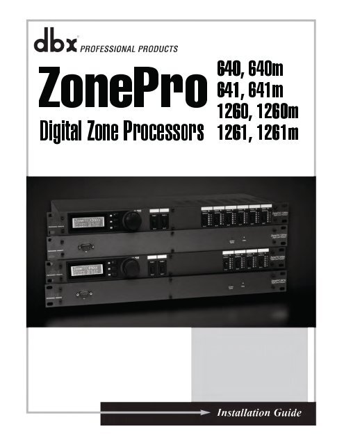
<strong>Install</strong>ation <strong>Guide</strong>
IMPORTANT SAFETY INFORMATION<br />
The symbols shown above are internationally accepted symbols that warn of potential<br />
hazards with electrical products. The lightning flash with arrowpoint in an equilateral triangle<br />
means that there are dangerous voltages present within the unit. The exclamation point<br />
in an equilateral triangle indicates that it is necessary for the user to refer to the owner’s<br />
manual.<br />
These symbols warn that there are no user serviceable parts inside the unit. Do not open the<br />
unit. Do not attempt to service the unit yourself. Refer all servicing to qualified personnel.<br />
Opening the chassis for any reason will void the manufacturer’s warranty. Do not get the<br />
unit wet. If liquid is spilled on the unit, shut it off immediately and take it to a dealer for<br />
service. Disconnect the unit during storms to prevent damage.<br />
Safety Instructions<br />
Notice For Customers If Your Unit Is Equipped With A Power Cord.<br />
WARNING: THIS APPLIANCE SHALL BE CONNECTED TO A MAINS SOCKET OUTLET WITH A PROTECTIVE EARTHING<br />
CONNECTION.<br />
The cores in the mains lead are coloured in accordance with the following code:<br />
GREEN and YELLOW - Earth BLUE - Neutral BROWN - Live<br />
As colours of the cores in the mains lead of this appliance may not correspond with the coloured markings<br />
identifying the terminals in your plug, proceed as follows:<br />
• The core which is coloured green and yellow must be connected to the terminal in the plug marked with the<br />
letter E, or with the earth symbol, or coloured green, or green and yellow.<br />
• The core which is coloured blue must be connected to the terminal marked N or coloured black.<br />
• The core which is coloured brown must be connected to the terminal marked L or coloured red.<br />
This equipment may require the use of a different line cord, attachment plug, or both, depending on the<br />
available power source at installation. If the attachment plug needs to be changed, refer servicing to qualified<br />
service personnel who should refer to the table below. The green/yellow wire shall be connected directly to<br />
the units chassis.<br />
WIRE COLOR<br />
CONDUCTOR<br />
Normal Alt<br />
L LIVE BROWN BLACK<br />
N NEUTRAL BLUE WHITE<br />
E EARTH GND<br />
GREEN/<br />
YEL<br />
GREEN<br />
WARNING: If the ground is defeated, certain fault conditions in the unit or in the system to which it is connected<br />
can result in full line voltage between chassis and earth ground. Severe injury or death can then result if the<br />
chassis and earth ground are touched simultaneously.<br />
If you want to dispose this product, do not mix it with general household waste. There is a<br />
separate collection system for used electronic products in accordance with legislation that<br />
requires proper treatment, recovery and recycling.<br />
Private household in the 25 member states of the EU, in Switzerland and Norway may return their used<br />
electronic products free of charge to designated collection facilities or to a retailer (if you purchase a similar<br />
new one).<br />
For Countries not mentioned above, please contact your local authorities for a correct method of disposal.<br />
By doing so you will ensure that your disposed product undergoes the necessary treatment, recovery and<br />
recycling and thus prevent potential negative effects on the environment and human health.<br />
WARNING FOR YOUR PROTECTION<br />
READ THE FOLLOWING:<br />
KEEP THESE INSTRUCTIONS<br />
HEED ALL WARNINGS<br />
FOLLOW ALL INSTRUCTIONS<br />
the apparatus shall not be exposed to dripping or<br />
splashing liquid and no object filled withi liquid,<br />
such as vases, shall be placed on the apparatus.<br />
CLEAN ONLY WITH A DRY CLOTH.<br />
DO NOT BLOCK ANY OF THE VENTILATION OPENINGS.<br />
INSTALL IN ACCORDANCE WITH THE MANUFACTURER’S<br />
INSTRUCTIONS.<br />
DO NOT INSTALL NEAR ANY HEAT SOURCES SUCH AS RA-<br />
DIATORS, HEAT REGISTERS, STOVES, OR OTHER APPARATUS<br />
(INCLUDING AMPLIFIERS) THAT PRODUCE HEAT.<br />
ONLY USE ATTACHMENTS/ACCESSORIES SPECIFIED BY THE<br />
MANUFACTURER.<br />
UNPLUG THIS APPARATUS DURING LIGHTNING STORMS OR<br />
WHEN UNUSED FOR LONG PERIODS OF TIME.<br />
Do not defeat the safety purpose of the polarized or groundingtype<br />
plug. A polarized plug has two blades with one wider than the<br />
other. A grounding type plug has two blades and a third grounding<br />
prong. The wide blade or third prong are provided for your safety.<br />
If the provided plug does not fit your outlet, consult an electrician<br />
for replacement of the obsolete outlet.<br />
Protect the power cord from being walked on or pinched particularly<br />
at plugs, convenience receptacles, and the point where they<br />
exit from the apparatus.<br />
Use only with the cart stand, tripod bracket, or table specified by<br />
the manufacture, or sold with the apparatus. When a cart is used,<br />
use caution when moving the cart/apparatus <strong>com</strong>bination to avoid<br />
injury from tip-over.<br />
Refer all servicing to qualified service personnel. Servicing is<br />
required when the apparatus has been damaged in any way, such<br />
as power-supply cord or plug is damaged, liquid has been spilled<br />
or objects have fallen into the apparatus, the apparatus has been<br />
exposed to rain or moisture, does not operate normally, or has<br />
been dropped.<br />
POWER ON/OFF SWITCH: If the equipment has a Power switch,<br />
the Power switch used in this piece of equipment DOES NOT<br />
break the connection from the mains.<br />
MAINS DISCONNECT: The plug shall remain readily operable.<br />
For rack-mount or installation where plug is not accessible, an<br />
all-pole mains switch with a contact separation of at least 3 mm in<br />
each pole shall be incorporated into the electrical installation of the<br />
rack or building.<br />
FOR UNITS EQUIPPED WITH EXTERNALLY ACCESSIBLE FUSE<br />
RECEPTACLE: Replace fuse with same type and rating only.<br />
MULTIPLE-INPUT VOLTAGE: This equipment may require the use<br />
of a different line cord, attachment plug, or both, depending on the<br />
available power source at installation. Connect this equipment only<br />
to the power source indicated on the equipment rear panel. To<br />
reduce the risk of fire or electric shock, refer servicing to qualified<br />
service personnel or equivalent.<br />
If connected to 240V supply, a suitable CSA/UL certified power<br />
cord shall be used for this supply.
IMPORTANT SAFETY INFORMATION<br />
Manufacturer’s Name:<br />
Manufacturer’s Address:<br />
declares that the product:<br />
Product option:<br />
DECLARATION OF<br />
CONFORMITY<br />
dbx Professional Products<br />
8760 S. Sandy Parkway<br />
sandy, Utah 84070, USA<br />
Product name: dbx <strong>640m</strong>, dbx<strong>641m</strong><br />
Note: Product name may be suffixed by the EU.<br />
None<br />
conforms to the following Product Specifications:<br />
Safety: iec 60065 (7th ed. 2001)<br />
Manufacturer’s Name:<br />
Manufacturer’s Address:<br />
declares that the product:<br />
Product option:<br />
DECLARATION OF<br />
CONFORMITY<br />
dbx Professional Products<br />
8760 S. Sandy Parkway<br />
sandy, Utah 84070, USA<br />
Product name: dbx1260m, dbx1261m<br />
Note: Product name may be suffixed by the EU.<br />
None<br />
conforms to the following Product Specifications:<br />
Safety: iec 60065 (7th ed. 2001)<br />
EMC:<br />
eN 55013 (2001+A1)<br />
eN 55020 (1998)<br />
EMC:<br />
eN 55013 (2001+A1)<br />
eN 55020 (1998)<br />
Supplementary Information:<br />
The product herewith <strong>com</strong>plies with the requirements of the Low<br />
Voltage Directive 2006/95/EC and the EMC Directive 2004/108/<br />
EC.<br />
Vice-President of Engineering<br />
8760 S. Sandy Parkway<br />
sandy, Utah 84070, USA<br />
date: April 6, 2009<br />
European Contact: Your local dbx Sales and Service Office or<br />
harman Music Group<br />
8760 South Sandy Parkway<br />
sandy, Utah 84070, USA<br />
ph: (801) 566-8800<br />
Fax: (801) 568-7583<br />
ELECTROMAGNETIC<br />
COMPATIBILITY<br />
This unit conforms to the Product Specifications noted on the<br />
Declaration of Conformity. Operation is subject to the following<br />
two conditions:<br />
• this device may not cause harmful interference, and<br />
• this device must accept any interference received, including<br />
interference that may cause undesired operation.<br />
Operation of this unit within significant electromagnetic fields should<br />
be avoided.<br />
• use only shielded interconnecting cables.<br />
U.K. MAINS PLUG WARNING<br />
A molded mains plug that has been cut off from the cord is<br />
unsafe. Discard the mains plug at a suitable disposal facility.<br />
NEVER UNDER ANY CIRCUMSTANCES SHOULD<br />
YOU INSERT A DAMAGED OR CUT MAINS PLUG<br />
INTO A 13 AMP POWER SOCKET.<br />
Do not use the mains plug without the fuse cover in place.<br />
Replacement fuse covers can be obtained from your local<br />
retailer. Replacement fuses are 13 amps and MUST be ASTA<br />
approved to BS1362.
Table of Contents<br />
<strong>ZonePro</strong> TM<br />
Section 1 - Introduction......................... 1<br />
1.2 Service Contact Info....................... 2<br />
1.3 Warranty....................................... 3<br />
Section 2 - Getting Started....................... 4<br />
2.1 640/<strong>640m</strong>, 1260/1260m Front<br />
Panels................................................ 4<br />
2.2 641/<strong>641m</strong>, 1261/1261m Front<br />
Panels................................................ 6<br />
2.3 640/641, <strong>640m</strong>/<strong>641m</strong> Rear Panel..... 7<br />
Section 3 - Wiring.................................. 9<br />
3.1 <strong>ZonePro</strong> Wiring.............................. 9<br />
Section 4 - Appendix............................... 13<br />
4.1 <strong>ZonePro</strong> <strong>640m</strong>/<strong>641m</strong> Block Diagram.. 13<br />
4.2 <strong>ZonePro</strong> 1260m/1261m Block<br />
Diagram............................................. 14<br />
Section 4 - Technical Specifications.......... 15<br />
®
<strong>ZonePro</strong> TM Introduction Section 1<br />
Section 1 - Introduction<br />
The ZonePRO family of Digital Zone Processors consists of eight devices with different<br />
functionality. Each device, with optional control from an extensive range of Zone Controllers,<br />
represents an inexpensive and quickly-deployed solution for a diverse range of <strong>com</strong>mercial<br />
audio applications. The Configuration Wizard guides you through the step-by-step<br />
configuration process, ensuring that you go from requirements to solution in just a few mouse<br />
clicks.<br />
Inputs<br />
Outputs<br />
Front Panel<br />
Control<br />
Mic Preamps S/PDIF Ethernet<br />
Mix<br />
Functionality<br />
1260m 12 6 Q 6 Q Q Q Q<br />
1260 12 6 Q 2 Q Q Q<br />
1261m 12 6 6 Q Q Q Q<br />
1261 12 6 2 Q Q Q<br />
<strong>640m</strong> 6 4 Q 4 Q Q Q<br />
640 6 4 Q 2<br />
<strong>641m</strong> 6 4 4 Q Q Q<br />
641 6 4 2<br />
ANC<br />
®<br />
1
Section 1<br />
Introduction<br />
1.2 Service Contact Info<br />
<strong>ZonePro</strong> TM<br />
If you require technical support, contact dbx Technical Support. Be prepared to accurately<br />
describe the problem. Know the serial number of your device - this is printed on a sticker<br />
attached to the chassis. If you have not already taken the time to fill out your warranty<br />
registration card and send it in, please do so now. You may also register online at www.<br />
dbxpro.<strong>com</strong>.<br />
Before you return a product to the factory for service, we re<strong>com</strong>mend you refer to the manual.<br />
Make sure you have correctly followed installation steps and operation procedures. For further<br />
technical assistance or service, please contact our Technical Support Department at (801)<br />
568-7660 or visit www.dbxpro.<strong>com</strong>. If you need to return a product to the factory for service,<br />
you MUST first contact Technical Support to obtain a Return Authorization Number.<br />
No returned products will be accepted at the factory without a Return Authorization Number.<br />
Please refer to the Warranty information on the following page, which extends to the first<br />
end-user. After expiration of the warranty, a reasonable charge will be made for parts, labor,<br />
and packing if you choose to use the factory service facility. In all cases, you are responsible<br />
for transportation charges to the factory. dbx will pay return shipping if the unit is still under<br />
warranty.<br />
Use the original packing material if it is available. Mark the package with the name of the<br />
shipper and with these words in red: DELICATE INSTRUMENT, FRAGILE! Insure the package<br />
properly. Ship prepaid, not collect. Do not ship parcel post.<br />
2<br />
®
1.3 Warranty<br />
<strong>ZonePro</strong> TM<br />
Introduction<br />
Section 1<br />
This warranty is valid only for the original purchaser and only in the United States.<br />
1. The warranty registration card that ac<strong>com</strong>panies this product must be mailed within 30<br />
days after purchase date to validate this warranty. You can also register online at<br />
www.dbxpro.<strong>com</strong>. Proof-of-purchase is considered to be the responsibility of the consumer. A<br />
copy of the original purchase receipt must be provided for any warranty service.<br />
2. dbx warrants this product, when bought and used solely within the U.S., to be free from<br />
defects in materials and workmanship under normal use and service.<br />
3. dbx liability under this warranty is limited to repairing or, at our discretion, replacing<br />
defective materials that show evidence of defect, provided the product is returned to dbx<br />
WITH RETURN AUTHORIZATION from the factory, where all parts and labor will be covered up<br />
to a period of two years. A Return Authorization number must first be obtained from dbx. The<br />
<strong>com</strong>pany shall not be liable for any consequential damage as a result of the product’s use in<br />
any circuit or assembly.<br />
4. dbx reserves the right to make changes in design or make additions to or improvements<br />
upon this product without incurring any obligation to install the same additions or<br />
improvements on products previously manufactured.<br />
5. The foregoing is in lieu of all other warranties, expressed or implied, and dbx neither<br />
assumes nor authorizes any person to assume on its behalf any obligation or liability in<br />
connection with the sale of this product. In no event shall dbx or its dealers be liable for<br />
special or consequential damages or from any delay in the performance of this warranty due to<br />
causes beyond their control.<br />
®<br />
3
Section 2<br />
Getting Started<br />
<strong>ZonePro</strong> TM<br />
Section 2 - Getting Started<br />
2.1 640/<strong>640m</strong>, 1260/1260m Front Panels<br />
640 Front Panel<br />
<strong>640m</strong> Front Panel<br />
1260 Front Panel<br />
Z onePRO1260<br />
Digital Zone Processor<br />
SELECT<br />
SELECT<br />
SELECT<br />
SELECT<br />
SELECT<br />
SELECT<br />
SELECT<br />
SELECT<br />
1260m Front Panel<br />
SELECT<br />
SELECT<br />
SELECT<br />
SELECT<br />
SELECT<br />
SELECT<br />
SELECT<br />
SELECT<br />
Front Panel LCD<br />
Information relating to parameters such as source selection, page steering, zone volumes and<br />
mutes.<br />
Parameter Select Buttons 1-3<br />
Allow selection of parameters.<br />
4<br />
®
<strong>ZonePro</strong> TM<br />
Getting Started<br />
Section 2<br />
Data Wheel<br />
The Data wheel is used to select and edit parameter values.<br />
Page Buttons<br />
Allow paging microphone path selection and page steering.<br />
Output Meter<br />
Six-segment output meter representing -30dBu to +20dBu.<br />
Output Select Button<br />
Allows selection of output for front panel control.<br />
Threshold Indicator<br />
Indicates that the threshold level has been exceeded within the output Compressor, Auto<br />
Gain Control or Limiter sections (and therefore gain reduction may be taking place).<br />
®<br />
5
Section 2<br />
Getting Started<br />
<strong>ZonePro</strong> TM<br />
2.2 641/<strong>641m</strong>, 1261/1261m Front Panels<br />
641 Front Panel<br />
<strong>641m</strong> Front Panel<br />
1261 Front Panel<br />
ZonePRO1261<br />
Digital Zone Processor<br />
NETWORK<br />
TRAFFIC<br />
POWER<br />
1261m Front Panel<br />
PC Connection<br />
This DB-9 connection is used to <strong>com</strong>municate to the PC via RS-232 protocol.<br />
Power LED<br />
This LED (when lighted), indicates that the <strong>ZonePro</strong> 641 is currently powered.<br />
Network Traffic (<strong>641m</strong>, 1261, and 1261m only)<br />
This LED (when lighted), indicates that network traffic is present.<br />
6<br />
®
<strong>ZonePro</strong> TM<br />
2.3 640/641, <strong>640m</strong>/<strong>641m</strong> Rear Panel<br />
640/641 Rear Panel<br />
Getting Started<br />
Section 2<br />
<strong>640m</strong>/<strong>641m</strong> Rear Panel<br />
RS-232<br />
ZC INPUT<br />
OUTPUTS<br />
LINK INPUT<br />
SOURCE<br />
MIC/LINE<br />
MIC/LINE<br />
CH 4 CH 3<br />
CH 2<br />
CH 1<br />
L<br />
MIC GAIN<br />
MIC<br />
(R) CLIP<br />
CLIP (R)<br />
(G) SIGNAL SIGNAL (G)<br />
ML 4 ML 3<br />
MIC GAIN<br />
MIC<br />
MIC GAIN<br />
MIC<br />
(R) CLIP<br />
CLIP (R)<br />
(G) SIGNAL SIGNAL (G)<br />
ML 2 ML 1<br />
MIC GAIN<br />
MIC<br />
R<br />
ETHERNET<br />
ZC INPUT<br />
LINK OUTPUT<br />
S2<br />
S1<br />
LINE<br />
LINE<br />
LINE<br />
LINE<br />
1260/1261 Rear Panel<br />
PC<br />
ZC INPUT<br />
OUTPUTS<br />
LINK INPUT<br />
SOURCE MIC/LINE<br />
(R) CLIP<br />
CLIP (R)<br />
(G) SIGNAL SIGNAL (G)<br />
L L L<br />
L L L<br />
L<br />
MIC GAIN<br />
MIC GAIN<br />
CH 6 CH 5 CH 4<br />
CH 3 CH 2 CH 1 ML 2 ML 1<br />
LINE<br />
MIC<br />
LINE<br />
MIC<br />
R<br />
R R R<br />
R R R<br />
S/PDIF<br />
INPUT<br />
10/100 BaseT<br />
ZC INPUT<br />
LINK OUTPUT<br />
S8 S7 S6 S4 S2<br />
S5 S3 S1<br />
1260m/1261m Rear Panel<br />
RS-232<br />
Power Connector<br />
IEC power connector<br />
RS-232 Port / PC Connector<br />
Serial port for configuration, control, monitoring and third party control.<br />
S/PDIF Input<br />
Digital audio input for up to two channels.<br />
®<br />
7
Section 2<br />
Getting Started<br />
<strong>ZonePro</strong> TM<br />
Ethernet Connector (<strong>640m</strong>, <strong>641m</strong>, 1260m, and 1261m only)<br />
Ethernet connector for configuration, control, monitoring and third party control.<br />
ZC Ports<br />
Allow connection of up to 12 ZC controllers (six per port) for control of ZonePRO parameters.<br />
Analog Outputs<br />
Balanced connections for analog audio outputs.<br />
Link Input/Output<br />
Allows duplication of the first six audio channels to another ZonePRO device in applications<br />
where additional output zones are required.<br />
RCA Inputs<br />
Mono-summed pairs of unbalanced RCA audio inputs.<br />
Mic/Line Inputs<br />
Switchable mic/line audio inputs.<br />
Mic Gain Control<br />
Allows microphone gain control.<br />
Mic/Line Switch<br />
Allows configuration for microphone or line level signals.<br />
Mic/Line Connector<br />
The input section provides two Euroblock connectors for mic/line inputs.<br />
Signal/Clip LED<br />
Indicates signal present or clip.<br />
8<br />
®
<strong>ZonePro</strong> TM<br />
Section 3 - Wiring<br />
Wiring<br />
Section 3<br />
3.1 <strong>ZonePro</strong> Wiring<br />
Zone Controller <strong>Install</strong>ation<br />
The installation of the Zone Controllers MUST be ac<strong>com</strong>plished with the use of cable which is<br />
rated VW-1 or higher. Common NEC designations which meet this rating include: CMP, CMR,<br />
CMG, CM and CMX.<br />
ZC-1 - The ZC-1 is a programmable zone controller that allows input or output volume level<br />
control from a wall panel.<br />
ZC-2 - The ZC-2 is a programmable zone controller that allows input or output volume level<br />
and mute control from a wall panel.<br />
ZC-3 - The ZC-3 allows wall panel routing and Actions selection for the SC devices.<br />
ZC-4 - The ZC-4 provides contact closure routing and Actions selection for room <strong>com</strong>bining or<br />
fire safety applications.<br />
ZC-Fire - The ZC-Fire is the interface to generic fire alarm relays. When fire alarm activates,<br />
the general purpose relay can typically be programmed to close if normally open or<br />
vices-versa. The ZC-fire interface unit monitors the state of the relay (n.o. or n.c.) and upon<br />
the state of change, notifies the SC 32/64, which then mutes its outputs.<br />
ZC-6 - The ZC-6 is a push-button up and down input or output volume controller.<br />
ZC-7 - The ZC-7 allows Actions selection for the SC devices.<br />
ZC-8 - The ZC-8 is used for a <strong>com</strong>bination of input or output volume up/down, and four<br />
position source/program select.<br />
ZC-9 - The ZC-9 allows wall panel routing and Actions selection for the SC devices.<br />
ZC-BOB - The ZC-BOB allows parallel or home run cabling of the Zone Controllers.<br />
®<br />
9
Section 3<br />
Wiring<br />
<strong>ZonePro</strong> TM<br />
Diagram A<br />
Diagram B<br />
ID# 1 ID# 4<br />
80-1342-A<br />
UL-6500<br />
80-1342-A<br />
UL-6500<br />
IEC60065<br />
IEC60065<br />
RJ45<br />
CONNECT ONLY TO<br />
ZONE CONTROLLER<br />
I N P U T .<br />
RJ45<br />
CONNECT ONLY TO<br />
ZONE CONTROLLER<br />
I N P U T .<br />
RS-232<br />
Diagram C<br />
RS-232<br />
10<br />
®
<strong>ZonePro</strong> TM<br />
Wiring<br />
Section 3<br />
Cable Specification: EIA/TIA 568A Standard (pin to pin) 24 AWG wire<br />
RJ-45<br />
(8-Position)<br />
1<br />
2<br />
3<br />
4<br />
5<br />
6<br />
7<br />
8<br />
White/Green<br />
Green<br />
White/Orange<br />
Blue<br />
White/Blue<br />
Orange<br />
White/Brown<br />
Brown<br />
RJ-45<br />
(8-Position)<br />
1<br />
2<br />
3<br />
4<br />
5<br />
6<br />
7<br />
8<br />
-VREF<br />
-Dip 1<br />
-Dip 2<br />
-Dip 3<br />
-Dip 4<br />
-Dip 5<br />
-Dip 6<br />
-GND<br />
Diagram A<br />
RS-232<br />
Diagram B<br />
RS-232<br />
Diagram C<br />
RS-232<br />
®<br />
11
Section 3<br />
Wiring<br />
<strong>ZonePro</strong> TM<br />
SC 32 / 64.<br />
12<br />
®
<strong>ZonePro</strong> TM<br />
Section 4 - Appendix<br />
Block Diagrams<br />
Appendix<br />
4.1 <strong>ZonePro</strong> <strong>640m</strong>/<strong>641m</strong> Block Diagram<br />
Zone Pro <strong>640m</strong>/<strong>641m</strong> Block Diagram<br />
Ethernet<br />
ZC<br />
Jack 1<br />
ZC<br />
Jack 2<br />
1261 only<br />
Link In/Out<br />
Link In/Out<br />
Output 1<br />
Output 2<br />
Output 3<br />
Output 4<br />
L<br />
R<br />
+<br />
Link In/Out<br />
Output 5<br />
Output 6<br />
L<br />
R<br />
+<br />
Link In/Out<br />
®<br />
13
Appendix<br />
Block Diagrams<br />
<strong>ZonePro</strong> TM<br />
4.2 <strong>ZonePro</strong> 1260m/1261m Zone Pro 1260m/1261m Block DiagramBlock Diagram<br />
Ethernet<br />
ZC<br />
Jack 1<br />
ZC<br />
Jack 2<br />
1261 only<br />
Link In/Out<br />
Link In/Out<br />
Output 1<br />
Output 2<br />
Output 3<br />
Output 4<br />
Output 5<br />
Output 6<br />
L<br />
R<br />
+<br />
Link In/Out<br />
L<br />
R<br />
+<br />
Link In/Out<br />
L<br />
R<br />
+<br />
Link In/Out<br />
L<br />
R<br />
+<br />
Link In/Out<br />
S/PDIF<br />
+<br />
14<br />
®
<strong>ZonePro</strong> TM<br />
Technical Specifications<br />
Appendix<br />
Section 4 - Technical Specifications<br />
640/641<br />
Analog Inputs:<br />
Number of Inputs:<br />
Connectors:<br />
Type:<br />
Impedance:<br />
Max input line level:<br />
CMRR:<br />
Mic Pre gain:<br />
Mic EIN:<br />
Mic Phantom Power:<br />
(6 Total) (2) Switchable line or mic inputs (4) RCA Source<br />
Euroblock(Line and Mic) RCA (Source)<br />
Electronically balanced/RF filtered<br />
> 50 kΩ Balanced, >75 kΩ Unbalanced<br />
+20 dBu Mic/Line, +12 dBu RCA<br />
> 40 dB, typically >55 dB @ 1 kHz<br />
30 to 60 dB<br />
< 118 dB, 22 Hz-22 kHz, 150 Ω<br />
15 V<br />
Analog Outputs:<br />
Number of Outputs: (4)<br />
Connectors:<br />
Euroblock<br />
Type:<br />
Electronically balanced, RF filtered<br />
Impedance:<br />
120 Ω balanced, 60 Ω unbalanced<br />
Max Output Level: +20dBu<br />
A/D Performance:<br />
Type:<br />
Dynamic Range line:<br />
Type IV dynamic range:<br />
Sample Rate:<br />
D/A Performance:<br />
Dynamic Range:<br />
dbx Type IV conversion system<br />
>113 dB A-weighted, >110 dB unweighted<br />
>119 dB, A-weighted, 22kHz BW<br />
>117 dB, unweighted, 22kHz BW<br />
48 kHz<br />
112 dB A-weighted, 109dB unweighted<br />
System Performance:<br />
Dynamic Range: >109 dB A-weighted, >106 dB unweighted,<br />
THD+N:<br />
0.003% typical at +4 dBu, 1 kHz, 0 dB gain<br />
Frequency Response: 20 Hz – 20 kHz, +/- 0.5 dB<br />
Interchannel Crosstalk: >80 dB typical<br />
Crosstalk input to output: >80 dB<br />
Propagation Delay: 0.6 msec<br />
Operating voltage: 100 VAC, 50/60Hz, 120 VAC, 60 Hz, 230 VAC 50/60 Hz<br />
Power Requirements: 29 Watts<br />
Physical:<br />
Weight: 6.8 lbs.(3.1 kg) Shipping weight 8.8 lbs. (4.0 kg)<br />
Dimensions: 1.75” H x 7.75” D x 19” W<br />
®<br />
15
Appendix<br />
1260/1261<br />
Technical Specifications<br />
<strong>ZonePro</strong> TM<br />
Analog Inputs:<br />
Number of Inputs:<br />
Connectors:<br />
Type:<br />
Impedance (Euroblock):<br />
Impedance (RCA):<br />
Max input line level:<br />
CMRR:<br />
Mic Pre gain:<br />
Mic EIN:<br />
Mic Phantom Power:<br />
12 Total (2) Switchable mic or line, (8) RCA, and (1) S/PDIF<br />
Euroblock (Line and Mic), RCA (Source) and RCA (S/PDIF)<br />
Electronically balanced, RF filtered<br />
> 50 kΩ Balanced, >25 kΩ Unbalanced, RF Filtered<br />
>25 kΩ Unbalanced, RF Filtered<br />
+20 dBu Mic/Line, +12 dBu RCA<br />
> 40 dB, typically >55 dB @ 1 kHz<br />
30 to 60 dB<br />
> 118 dB, 22 Hz-22 kHz, 150 Ω Source Impedance<br />
15 V<br />
Analog Outputs:<br />
Number of Outputs: 6<br />
Connectors:<br />
Euroblock<br />
Type:<br />
Electronically balanced, RF filtered<br />
Impedance:<br />
120 Ω balanced, 60 Ω unbalanced<br />
Max Output Level: +20 dBu<br />
A/D Performance:<br />
Type:<br />
dbx Type IV conversion system<br />
Dynamic Range line: >113 dB A-weighted, >110 dB unweighted<br />
Type IV dynamic range: >119 dB, A-weighted, 22 kHz BW>117 dB, unweighted, 22<br />
kHz BW<br />
Sample Rate:<br />
48 kHz<br />
D/A Performance:<br />
Dynamic Range:<br />
112 dB A-weighted, 109 dB unweighted<br />
System Performance:<br />
Dynamic Range: >110 dB A-weighted, >107 dB unweighted,<br />
THD+N:<br />
0.003% typical at +4 dBu, 1 kHz, 0 dB gain<br />
Frequency Response: 20 Hz – 20 kHz, +/- 0.5 dB<br />
Interchannel Crosstalk: >80 dB typical<br />
Crosstalk input to output: >80 dB<br />
Propagation Delay: 0.6 msec<br />
Operating voltage: 100-240 VAC, 50/60Hz<br />
Power Requirements: 27 Watts<br />
dbx® incorporates high quality<br />
mechanical fans in some products. All<br />
mechanical fans have a limited life<br />
expectancy. We re<strong>com</strong>mend annual<br />
inspection of fans for dust occlusion<br />
and excessive noise. Fan assemblies<br />
should be replaced after six to ten<br />
years of use. Environmental factors<br />
such as elevated temperature, dust,<br />
and smoke can adversely affect<br />
fan life. Systems exposed to these<br />
conditions should be inspected more<br />
frequently. Fan replacement can be<br />
performed either at the factory or by<br />
an experienced technician in the field.<br />
Please contact dbx Technical Support<br />
for more information on purchasing<br />
replacement parts or product service.<br />
Physical:<br />
Weight:<br />
Dimensions:<br />
6.0 lbs.(2.7 kg) Shipping weight 8.0 lbs. (3.6 kg)<br />
1.75” H x 8” D x 19” W<br />
dbx® has a policy of continued product<br />
improvement and accordingly reserves<br />
the right to change features and<br />
specifications without prior notice.<br />
16<br />
®
<strong>640m</strong>/<strong>641m</strong><br />
<strong>ZonePro</strong> TM<br />
Technical Specifications<br />
Appendix<br />
Analog Inputs:<br />
Number of Inputs:<br />
Connectors:<br />
Type:<br />
Impedance:<br />
Max input line level:<br />
CMRR:<br />
Mic Pre gain:<br />
Mic EIN:<br />
Mic Phantom Power:<br />
(6 Total) (4) Switchable line or mic inputs (2) RCA Source<br />
Euroblock(Line and Mic) RCA (Source)<br />
Electronically balanced/RF filtered<br />
> 50 kΩ Balanced, >75 kΩ Unbalanced<br />
+20 dBu Mic/Line, +12 dBu RCA<br />
> 40 dB, typically >55 dB @ 1 kHz<br />
30 to 60 dB<br />
< 118 dB, 22 Hz-22 kHz, 150Ω<br />
15 V<br />
Analog Outputs:<br />
Number of Outputs: (4)<br />
Connectors:<br />
Euroblock<br />
Type:<br />
Electronically balanced, RF filtered<br />
Impedance:<br />
120 Ω balanced, 60 Ω unbalanced<br />
Max Output Level: +20 dBu<br />
A/D Performance:<br />
Type:<br />
Dynamic Range line:<br />
Type IV dynamic range:<br />
Sample Rate:<br />
D/A Performance:<br />
Dynamic Range:<br />
dbx Type IV conversion system<br />
>113 dB A-weighted, >110 dB unweighted<br />
>119 dB, A-weighted, 22 kHz BW<br />
>117 dB, unweighted, 22 kHz BW<br />
48 kHz<br />
112 dB A-weighted, 109 dB unweighted<br />
System Performance:<br />
Dynamic Range: >109 dB A-weighted, >106 dB unweighted,<br />
THD+N:<br />
0.003% typical at +4 dBu, 1 kHz, 0 dB gain<br />
Frequency Response: 20 Hz – 20 kHz, +/- 0.5 dB<br />
Interchannel Crosstalk: >80 dB typical<br />
Crosstalk input to output: >80 dB<br />
Propagation Delay: 0.6 msec<br />
Operating voltage: 100 VAC, 50/60 Hz, 120 VAC, 60 Hz, 230 VAC 50/60 Hz<br />
Power Requirements: 29 Watts<br />
Physical:<br />
Weight: 6.8 lbs.(3.1 kg) Shipping weight 8.8 lbs. (4.0 kg)<br />
Dimensions: 1.75” H x 8” D x 19” W<br />
®<br />
17
®<br />
Appendix<br />
1260m/1261m<br />
Technical Specifications<br />
<strong>ZonePro</strong> TM<br />
Analog Inputs:<br />
Number of Inputs:<br />
Connectors:<br />
Type:<br />
Impedance (Euroblock):<br />
Impedance (RCA):<br />
Max input line level:<br />
CMRR:<br />
Mic Pre gain:<br />
Mic EIN:<br />
Mic Phantom Power:<br />
10 Total (6) Switchable mic or line, (4) RCA, and (1) S/PDIF<br />
Euroblock (Line and Mic), RCA (Source) and RCA (S/PDIF)<br />
Electronically balanced, RF filtered<br />
> 50 kΩ Balanced, >25 kΩ Unbalanced, RF Filtered<br />
>25 kΩ Unbalanced, RF Filtered<br />
+20 dBu Mic/Line, +12 dBu RCA<br />
> 40 dB, typically >55 db @ 1kHz<br />
30 to 60 dB<br />
> 118 dB, 22 Hz-22 kHz, 150 Ω Source Impedance<br />
15 V<br />
Analog Outputs:<br />
Number of Outputs: 6<br />
Connectors:<br />
Euroblock<br />
Type:<br />
Electronically balanced, RF filtered<br />
Impedance:<br />
120 Ω balanced, 60 Ω unbalanced<br />
Max Output Level: +20 dBu<br />
A/D Performance:<br />
Type:<br />
Dynamic Range line:<br />
Type IV dynamic range:<br />
Sample Rate:<br />
D/A Performance:<br />
Dynamic Range:<br />
dbx Type IV conversion system<br />
>113 dB A-weighted, >110 dB unweighted<br />
>119 dB, A-weighted, 22 kHz BW>117 dB, unweighted, 22 kHz BW<br />
48 kHz<br />
112 dB A-weighted, 109dB unweighted<br />
System Performance:<br />
Dynamic Range: >110 dB A-weighted, >107 dB unweighted,<br />
THD+N:<br />
0.003% typical at +4 dBu, 1 kHz, 0 dB gain<br />
Frequency Response: 20 Hz – 20 kHz, +/- 0.5 dB<br />
Interchannel Crosstalk: >80 dB typical<br />
Crosstalk input to output: >80 dB<br />
Propagation Delay: 0.6 msec<br />
Operating voltage: 100-240 VAC, 50/60Hz<br />
Power Requirements: 27 Watts<br />
Physical:<br />
Weight:<br />
Dimensions:<br />
6.0 lbs.(2.7 kg) Shipping weight 8.0 lbs. (3.6 kg)<br />
1.75” H x 8” D x 19” W<br />
18
<strong>ZonePro</strong> TM<br />
®<br />
19
®<br />
8760 South Sandy Parkway • Sandy, Utah 84070<br />
Phone: (801) 568-7660 • Fax (801) 568-7662<br />
Int’l Fax: (801) 568-7583<br />
Questions or <strong>com</strong>ments?<br />
Contact us at www.dbxpro.<strong>com</strong><br />
Printed in the USA<br />
18-0676-A