PTC Thermistors POSISTOR ® for Circuit Protection - Murata
PTC Thermistors POSISTOR ® for Circuit Protection - Murata
PTC Thermistors POSISTOR ® for Circuit Protection - Murata

You also want an ePaper? Increase the reach of your titles
YUMPU automatically turns print PDFs into web optimized ePapers that Google loves.
!Note • Please read rating and !CAUTION (<strong>for</strong> storage, operating, rating, soldering, mounting and handling) in this catalog to prevent smoking and/or burning, etc.<br />
• This catalog has only typical specifications. There<strong>for</strong>e, please approve our product specifi cations or transact the approval sheet <strong>for</strong> product specifi cations be<strong>for</strong>e ordering.<br />
R90E.pdf<br />
Sep.24,2012<br />
Basic Characteristics of <strong>POSISTOR</strong>r<br />
Technical Terms<br />
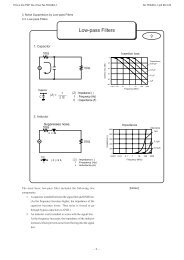
1. Protective Threshold Current<br />
The maximum current value is called the "Protective<br />
Threshold Current" <strong>for</strong> Voltage vs. Current characteristics<br />
(static).<br />
When smaller than the protective threshold current flows<br />
in <strong>POSISTOR</strong>r, it reaches its stability (as shown in figure<br />
on right) at the intersection (A) of the load curve (a) and<br />
voltage-current characteristics of <strong>POSISTOR</strong>r(c). And<br />
<strong>POSISTOR</strong>r works as a normal fixed resistor.<br />
However, when larger than protective threshold current<br />
flows, it stabilizes at the intersection (B) with the load<br />
curve (b).<br />
Load Curve of <strong>Circuit</strong> and Voltage - Current Characteristics<br />
of <strong>POSISTOR</strong>r<br />
a Load curve in normal state<br />
(normal current)<br />
b Load curve in abnormal state<br />
(abnormal current)<br />
c Voltage-current characteristics<br />
Vp<br />
of <strong>POSISTOR</strong>r<br />
E<br />
I = E - Vp<br />
RL<br />
I<br />
RL<br />
Current (log)<br />
b<br />
a<br />
A<br />
c<br />
B<br />
Voltage (log)<br />
E<br />
2. Protective Threshold Current Range<br />
Protective threshold current varies depending on the<br />
ambient temperature, resistance value, temperature<br />
characteristics and shape. (see Figure on right) The<br />
maximum value of trip current and the minimum value of<br />
the hold current are in the range of ambient temperature<br />
-10 to +60°C.<br />
That is, when a current is smaller than the hold current,<br />
<strong>POSISTOR</strong>r works only as a fixed resistor. When larger<br />
than the trip current flows, however, <strong>POSISTOR</strong>r<br />
protects the circuit from overload.<br />
Protective Threshold Current Range<br />
Current (mA)<br />
1000<br />
800<br />
Trip Current<br />
600<br />
Protective Threshold Current<br />
400<br />
Hold Current<br />
200<br />
0 -20 0 20 40 60<br />
Ambient Temperature (°C)<br />
3. Operating Time<br />
A period starting from the voltage input to the moment<br />
current itself sharply attenuates is called "Operating<br />
Time." Conventionally, operation time (t0) is determined<br />
to be the period until inrush current (I0) decreases to a<br />
level one half the original inrush current (I0/2).<br />
Operating Current<br />
Current (A)<br />
I0<br />
I0<br />
2<br />
Operating Time<br />
t 0<br />
Time (sec.)<br />
6