PTC Thermistors POSISTOR ® for Circuit Protection - Murata
PTC Thermistors POSISTOR ® for Circuit Protection - Murata
PTC Thermistors POSISTOR ® for Circuit Protection - Murata

You also want an ePaper? Increase the reach of your titles
YUMPU automatically turns print PDFs into web optimized ePapers that Google loves.
Continued from the preceding page.<br />
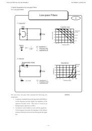
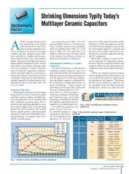
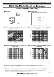
Lead Type PTGL/PTF Series Package<br />
Δh1<br />
Δh2<br />
e<br />
W0 W2<br />
H0 H2<br />
W1<br />
W<br />
l<br />
!Note • Please read rating and !CAUTION (<strong>for</strong> storage, operating, rating, soldering, mounting and handling) in this catalog to prevent smoking and/or burning, etc.<br />
• This catalog has only typical specifications. There<strong>for</strong>e, please approve our product specifi cations or transact the approval sheet <strong>for</strong> product specifi cations be<strong>for</strong>e ordering.<br />
R90E.pdf<br />
Sep.24,2012<br />
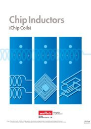
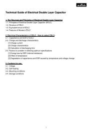
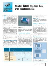
c Narrow Current Band 30 - 140V Series / 16 - 80V Series / Inrush Current Suppression Taping Dimensions<br />
P2<br />
D<br />
P<br />
ΔS<br />
T<br />
L<br />
P1<br />
F<br />
d<br />
øD0<br />
P0<br />
t2<br />
t1<br />
Item Code Dimensions (mm) Note<br />
Pitch of Component<br />
Pitch of Sprocket Hole<br />
Lead Spacing<br />
Length from Hole Center to Lead<br />
Length from Hole Center to Component Center<br />
Body Diameter<br />
Body Thickness<br />
Deviation along Tape, Left or Right Defect<br />
Carrier Tape Width<br />
Position of Sprocket Hole<br />
Lead Distance between Reference and<br />
Bottom Planes<br />
Protrusion Length<br />
Diameter of Sprocket Hole<br />
Lead Diameter<br />
Total Tape Thickness<br />
Total Thickness of Tape and Lead Wire<br />
Deviation across Tape<br />
Portion to cut in Case of Defect<br />
Hold down Tape Width<br />
Hold down Tape Position<br />
Coating Extension on Lead<br />
P<br />
P0<br />
F<br />
P1<br />
P2<br />
D<br />
T<br />
ΔS<br />
W<br />
W1<br />
H0<br />
H2<br />
I<br />
D0<br />
d<br />
t1<br />
t2<br />
Δh1, Δh2<br />
L<br />
W0<br />
W2<br />
e<br />
12.7<br />
12.7±0.3<br />
+0.8 5.0–0.3<br />
3.85±0.8<br />
6.35±1.3<br />
Please see in Ratings<br />
Please see in Ratings<br />
±1.5<br />
18.0±0.5<br />
9.0 +0.5<br />
–0.75<br />
16.0±1.0<br />
6.0 max.<br />
+0.5 to –1.0<br />
4.0±0.2<br />
Please see in Ratings<br />
0.6±0.3<br />
2.0 max.<br />
1.5 max.<br />
11.0 +0<br />
–2.0<br />
11.0 min.<br />
4.0 max.<br />
Up to the center of crimp<br />
Tolerance is determined by ΔS.<br />
Deviation in the feeding direction<br />
Including the inclination caused by lead bending<br />
Deviation of tape width<br />
Continued on the following page.<br />
99