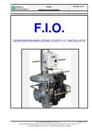
USER MANUAL FOR F.I.O. INSTALLATION - Pietro Fiorentini
USER MANUAL FOR F.I.O. INSTALLATION - Pietro Fiorentini
USER MANUAL FOR F.I.O. INSTALLATION - Pietro Fiorentini

Create successful ePaper yourself
Turn your PDF publications into a flip-book with our unique Google optimized e-Paper software.
2.2 ECU Electronic Control Unit<br />
2.2.1 Installation on board of the regulator:<br />
F.I.O.<br />
User’s Manual<br />
This configuration is required in case of indirect measurement of flow rate. The<br />
application Q-kit includes the bracket and the screws necessary for the fixing of the<br />
ECU. Furthermore it includes the cable for the connection of the displacement<br />
transducer to the ECU.<br />
Pict 1- Prepare the screws with the nut screwed on the bracket.<br />
Pict 2- Install the ECU and fix the screws<br />
Pict 3- Remove one of the small fairleads. Bring the cable for the connection of<br />
the displacement transducer to the ECU. There is a fairlead<br />
already assembled on it. Remove the fixing nut of the fairlead. Pass the white<br />
connector through the threaded hole.<br />
Pict 4- Insert the fixing nut of the fairlead through the connector and fix the<br />
nut on the fairlead.<br />
Pict 5- Insert the connector on the card<br />
Pict 6- From the other side of the cable screw the male connector on the female<br />
connection of the transducer.<br />
ENGLISH<br />
1 2 3<br />
4 5 6<br />
F.I.O. User Manual – Ed.2. Rev.5 Page 7/ 53<br />
The information contained in this document is confidential and the property of <strong>Pietro</strong> <strong>Fiorentini</strong> S.p.A.<br />
Technical data may undergo changes without notice