USER MANUAL FOR F.I.O. INSTALLATION - Pietro Fiorentini
USER MANUAL FOR F.I.O. INSTALLATION - Pietro Fiorentini
USER MANUAL FOR F.I.O. INSTALLATION - Pietro Fiorentini

Create successful ePaper yourself
Turn your PDF publications into a flip-book with our unique Google optimized e-Paper software.
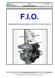
F.I.O.<br />
User’s Manual<br />
2. Installation of the single components<br />
PROCEDURE STEP 1:<br />
ENGLISH<br />
- Before starting the operations, close upstream and downstream ball or butterfly valves and discharge all the pressure in the line.<br />
- Installation of Q-kit, ECU, P-kit and P&CD. Refer to the following instructions.<br />
Note: if one of these units is not required, don’t consider the corresponding chapter.<br />
There is also a video showing all these operations.<br />
2.1 Q-kit<br />
The Q-kit consists of a device for the acquisition of the displacement % of the pressure<br />
regulator from the closing position. It is necessary for the calculation of the flow rate<br />
with the indirect method. It is composed on a resistive transducer supported by a<br />
suitable bracket and coupled to the stroke indicator of the regulator for the reading of<br />
the position. The transducer is covered by an aluminum cylinder in order to ensure the<br />
protection against atmospheric events. It is supplied already preassembled (see<br />
picture on the right). If it is an upgrade of an already installed regulator, start from Pict<br />
1, otherwise start from Pict 8:<br />
Pict 1- Disassemble the upper cover of the regulator<br />
Pict 2- Replace the upper flange with the flange supplied in the Q-kit.<br />
Pict 3- Replace the stroke indicator rod with the longer one supplied in the Q-kit.<br />
Pict 4- Move the upper cover toward the lower cover paying attention that the base of<br />
the stroke indicator rod is correctly inserted into the groove.<br />
Pict 5- Position correctly the upper cover and fix the screws.<br />
Pict 6- Insert the visual indicator of position and push it up to the end. Then insert the<br />
small glass.<br />
Pict 7- Fix the nut with anti-dust gasket.<br />
Pict 8- Position the Q-kit on the upper flange of the pressure regulator<br />
Pict 9- Insert the central screw.<br />
Pict 10- Fix the central screw.<br />
Pict 11- Couple, with the suitable junction, the position transducer with the extended<br />
rod of the pressure regulator.<br />
Pict 12- Verify, lifting manually the rod of the position transducer, that it can move for a<br />
stroke at least equal to the stroke indicated on the small glass of the visual<br />
indicator. In case the rod of the transducer is not able to translate enough,<br />
loosen the 4 fixing screws of the transducer on the bracket and lift it as<br />
needed. Fix again the 4 screws.<br />
Pict 13- Push the rod of the position transducer to the bottom so that the coupling is<br />
well fixed.<br />
Pict 14- Close the transducer with the cover<br />
Pict 15- Fixing it with the lateral screw.<br />
1 2 3<br />
F.I.O. User Manual – Ed.2. Rev.5 Page 5/ 53<br />
The information contained in this document is confidential and the property of <strong>Pietro</strong> <strong>Fiorentini</strong> S.p.A.<br />
Technical data may undergo changes without notice