USER MANUAL FOR F.I.O. INSTALLATION - Pietro Fiorentini
USER MANUAL FOR F.I.O. INSTALLATION - Pietro Fiorentini
USER MANUAL FOR F.I.O. INSTALLATION - Pietro Fiorentini

Create successful ePaper yourself
Turn your PDF publications into a flip-book with our unique Google optimized e-Paper software.
F.I.O.<br />
User’s Manual<br />
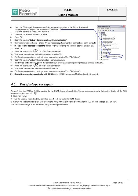
6- Insert the COM used. If necessary verify in the operating system of the PC on “Peripheral<br />
management \ COM port” the number of COM in use.<br />
FioTerm permits to select COM from 1 to 7.<br />
7- The other parameters are 9600; 8; none; 1.<br />
8- Press OK<br />
9- Open the window “Setup \ Communication \ Communication”.<br />
10- Connection modality: Local ; phone N° not necessary; Password of connection: conn (default)<br />
11- In “Device and address” select the device “P&CD” entering the Modbus address (default 20).<br />
12- Press OK<br />
13- Press the pushbutton “ GO ” or “File \ Start connection”.<br />
14- Wait some seconds and it should connect with the P&CD.<br />
15- Exit from the connection pressing the red pushbutton with the X or “File \ Close”.<br />
16- Open the window “Setup \ Communication \ Communication”.<br />
17- In “Device and address” select the device ECU1 entering the corresponding Modbus address (default 0).<br />
18- Press the pushbutton “ GO ”or “File \ Start connection”.<br />
19- Wait some seconds and it should connect with ECU1.<br />
20- Exit from the connection pressing the red pushbutton with the X or “File \ Close”.<br />
21- Repeat the procedure eventually with ECU2 (set on ECU2 the address ModBus default 10, see 4.4).<br />
4.6 Test of tele-power supply<br />
ENGLISH<br />
To verify that the ECU on field is supplied by the P&CD (external supply 230 Vac or solar panel) verify that on the display of the ECU<br />
appears the plug symbol<br />
If this is not, verify:<br />
1- That the selector inside the ECU is in Rem (see 4.1). If no, switch to REM. If yes:<br />
2- Extract the first connector of ECU on the left and verify with a voltmeter if is coming from P&CD the inlet voltage: 5V - 6.5 VDC.<br />
3- If the correct voltage is not measured, verify the wiring connections.<br />
F.I.O. User Manual – Ed.2. Rev.5 Page 21/ 53<br />
The information contained in this document is confidential and the property of <strong>Pietro</strong> <strong>Fiorentini</strong> S.p.A.<br />
Technical data may undergo changes without notice