Delta CTA, DePuy - ShoulderDoc.co.uk
Delta CTA, DePuy - ShoulderDoc.co.uk
Delta CTA, DePuy - ShoulderDoc.co.uk

Create successful ePaper yourself
Turn your PDF publications into a flip-book with our unique Google optimized e-Paper software.
Surgical Technique<br />
<strong>CTA</strong> TM<br />
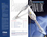
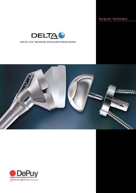
DELTA <strong>CTA</strong> REVERSE SHOULDER PROSTHESIS
Lateralised Cup Glenosphere Threaded Head Screw<br />
Spherical<br />
Head Screw<br />
Epiphysis<br />
Metaglene<br />
Diaphysis
Contents<br />
Surgical Steps 2<br />
Introduction 3<br />
Pre-operative Planning 4<br />
Surgical Approach and Patient Positioning 4<br />
Superior Lateral Approach 5<br />
Humeral Head Resection 6<br />
Humeral Reaming 7<br />
Distal Humeral Reaming (Revision Surgery) 8<br />
Proximal Reamer Guide Assembly 8<br />
Proximal Humeral Reaming 9<br />
Trial Humeral Implantation 10<br />
Exposure of the Glenoid 10<br />
Preparation of the Glenoid 11<br />
Implantation of the Metaglene 12<br />
Inferior and Superior Screw Placement 12<br />
Anterior and Posterior Screw Placement 14<br />
Trial Reduction 15<br />
Glenosphere Placement 16<br />
Humeral Implant Insertion 17<br />
Hemi-arthroplasty 18<br />
Closure 19<br />
Post-operative Management 19<br />
Ordering Information 20<br />
1
Surgical Steps<br />
Superior lateral approach<br />
Resection of the humeral head<br />
Diaphyseal preparation<br />
Proximal reaming of the humerus<br />
Preparation of the glenoid<br />
Insertion of the Metaglene<br />
Glenosphere Placement<br />
Insertion of the humeral Implant<br />
2
Introduction<br />
Anatomical<br />
centre of rotation<br />
Anatomical<br />
centre of rotation<br />
Medialised<br />
centre of rotation<br />
Figure 1 Figure 2<br />
The <strong>Delta</strong> <strong>CTA</strong> Reverse Shoulder<br />
System is indicated for the treatment<br />
of glenohumeral arthritis when it is<br />
associated with irreparable rotator cuff<br />
damage and where <strong>co</strong>nventional total<br />
shoulder arthroplasty may not be fully<br />
effective in restoring joint stability with<br />
an adequate range of movement.<br />
The design avoids high shear forces<br />
associated with unstable <strong>co</strong>nventional<br />
or hemi-arthroplasty, that can cause the<br />
implant to wear and loosen.<br />
The <strong>Delta</strong> <strong>CTA</strong> prosthetic geometry<br />
reverses the normal relationship<br />
between scapular and humeral<br />
<strong>co</strong>mponents, moving the centre of<br />
rotation medially and distally to<br />
increase the lever arm length of the<br />
deltoid muscle (Figures 1 and 2).<br />
This allows the three muscles in the<br />
deltoid group to <strong>co</strong>mpensate for rotator<br />
cuff deficiency, drawing the articulating<br />
surfaces together to stabilise the joint<br />
and allow as near normal function<br />
as possible.<br />
3
Pre-operative Planning<br />
Surgical Approach and Patient Positioning<br />
Figure 3 Figure 4<br />
An initial assessment is made of the<br />
bone in the superior and inferior<br />
aspects of the glenoid, using<br />
radiographic and CT imaging in order<br />
to determine the suitability of the<br />
patient for treatment. The size of the<br />
glenoid vault is assessed to ensure that<br />
all four metaglene screws can be placed<br />
within glenoid bone.<br />
Pre-operative planning is also carried<br />
out, using AP and lateral shoulder<br />
radiographs of known magnification,<br />
and the available template to <strong>co</strong>nfirm<br />
the size and alignment of the implant<br />
(Figure 3).<br />
The patient should be in the deck chair<br />
position, with the affected arm <strong>co</strong>mpletely<br />
free and resting on a support (Figure 4).<br />
4
Superior Lateral Approach<br />
Figure 5 Figure 6<br />
The quality and ease of implantation<br />
rely on a superior lateral approach<br />
(Figure 5). A delto-pectoral approach is<br />
also appropriate and the choice depends<br />
mainly on surgeon preference and<br />
clinical parameters. Revision surgery for<br />
instance usually dictates a delto-pectoral<br />
approach as it allows for a longer<br />
humeral incision when faced with a<br />
difficult removal of the humeral stem.<br />
Used for classic rotator cuff repairs, the<br />
superior lateral approach allows a clear<br />
visualisation of the glenoid and<br />
therefore facilitates greatly the<br />
implantation of the glenoid<br />
<strong>co</strong>mponents of the prosthesis.<br />
The incision is started at the level of the<br />
AC joint, follows the anterior aspect of<br />
the acromion and finishes vertically<br />
downwards for 4 cm (Figure 6).<br />
Following subcutaneous dissection, the<br />
anterior and middle deltoid muscle<br />
bundles are separated opposite the<br />
lateral margin of the acromion, using<br />
blunt dissection (the dissection should<br />
not extend beyond 4 cm from the<br />
external aspect of the acromion in<br />
order to preserve the axillary nerve).<br />
When the subacromial bursa is visible,<br />
gentle longitudinal traction in line with<br />
the limb will allow a retractor to be<br />
placed in the subacromial space.<br />
The anterior deltoid is released<br />
subperiosteally from its acromial<br />
insertion up to the AC joint.<br />
The humeral head is then visible at the<br />
anterior edge of the acromion – the<br />
subacromial bursa is removed.<br />
If necessary, exposure may now be<br />
improved by dividing the AC ligament<br />
and performing acromioplasty.<br />
The limb is then externally rotated and<br />
the head is dislocated anterosuperiorly<br />
to facilitate positioning of the cutting<br />
guide. If the biceps is still present, it<br />
should be tenodenised in the bicipital<br />
groove. Retain the teres minor and<br />
infraspinatus when present.<br />
5
Humeral Head Resection<br />
Orientation<br />
Pin<br />
Figure 8C<br />
Epi<strong>co</strong>ndylar<br />
Axis<br />
Figure 8B<br />
Figure 7<br />
Figure 8A<br />
An initial entry hole is made in the<br />
proximal humerus using an awl.<br />
The awl tip is centred over and in line<br />
with the long axis of the humerus, at<br />
the junction of the intratubercular<br />
groove and the articulating surface of<br />
the humeral head (Figure 7).<br />
The orientation pin is then passed<br />
through the hole in the resection<br />
guide <strong>co</strong>rresponding to the desired<br />
retroversion (Figure 8A). Preferably, this<br />
will be 0˚ since excessive retroversion<br />
will restrict joint rotation, especially in<br />
internal rotation. Retroversion is<br />
calculated with reference to the axis of<br />
the humeral epi<strong>co</strong>ndyles (Figure 8B).<br />
The tip of the cutting guide is located<br />
in the entry hole and the guide is<br />
passed down the humeral canal until<br />
it rests on the humeral head.<br />
With the humeral resection guide rim<br />
located on the humeral head, the<br />
orientation pin is aligned with the<br />
trans<strong>co</strong>ndylar axis (Figure 8C).<br />
6
Humeral Reaming<br />
Figure 9 Figure 10<br />
The humeral head resection is initiated<br />
in line with the inferior aspect of the<br />
humeral cutting guide (135°), the<br />
humeral cutting guide is removed and<br />
the resection <strong>co</strong>mpleted (Figure 9).<br />
The initial resection removes a minimal<br />
amount of bone. More bone may be<br />
removed if necessary.<br />
A forked retractor is passed under the<br />
scapula to lower the humerus. If this<br />
provides a clear sight of the glenoid<br />
surface, the resection level is <strong>co</strong>rrect.<br />
If not, a further resection may be<br />
carried out.<br />
Starting with the smallest diameter<br />
distal reamer attached to the T-Handle,<br />
the distal humeral canal is reamed in<br />
line with the long axis of the humerus<br />
(Figure 10). The final reamer should<br />
not exceed the templated proximal<br />
diameter (up to size 4). Reaming stops<br />
when the flange of the reamer is level<br />
with the resection.<br />
Power reaming should not be used<br />
to ream the humerus.<br />
7
Distal Humeral Reaming (Revision Surgery)<br />
Proximal Reamer Guide Assembly<br />
Figure 11<br />
Figure 12<br />
If a long stem is to be implanted,<br />
In addition to the reamers in the<br />
150 mm and 180 mm diaphyseal<br />
ac<strong>co</strong>mpanying table, 5 mm and 6 mm<br />
revision reamers should be used in<br />
diameter reamers are provided as<br />
<strong>co</strong>njunction with the rigid reamers that start-up reamers.<br />
are included within the <strong>Delta</strong> <strong>CTA</strong><br />
revision instrumentation (Figure 11).<br />
Diaphyseal references<br />
Reamer references<br />
Size 1, length 150 mm (ref. DHR115H/DHC115B)<br />
Size 1, length 180 mm (ref. DHR118H/DHC118B)<br />
7.5 mm diameter (ref. ALR 075)<br />
Size 2, length 150 mm (ref. DHR215H/DHC215B)<br />
Size 2, length 180 mm (ref. DHR218H/DHC218B)<br />
8 mm diameter (ref. ALR 008)<br />
Size 3, length 150 mm (ref. DHR315H/DHC315B)<br />
Size 3, length 180 mm (ref. DHR318H/DHC318B)<br />
9 mm diameter (ref. ALR 009)<br />
The proximal reaming guide, 36 mm or<br />
42 mm, <strong>co</strong>rresponding to the templated<br />
epiphysis size, is screwed to the trial<br />
diaphyseal stem that matches the distal<br />
reamer diameter. The assembly is<br />
mounted on the humeral stem impactor<br />
and introduced in line with the long<br />
axis of the humerus (Figure 12).<br />
8
Proximal Humeral Reaming<br />
Figure 13 Figure 14<br />
The orientation pin is passed through<br />
the hole in the impactor handle and<br />
the previously selected version angle<br />
is checked.<br />
The assembly is impacted into the<br />
humeral canal until the appropriate<br />
mark (36 mm or 42 mm) on the impactor<br />
reaches the level of the resection<br />
(Figure 13).<br />
Retroversion is again checked and<br />
the impactor is removed, leaving the<br />
reaming guide in place.<br />
The appropriate size of proximal humeral<br />
reamer, (36.1, 36.2 or 42.2 mm) is<br />
mounted on the T-Handle.<br />
The humerus is then reamed until<br />
the flange of the reamer is level with<br />
the osteotomy, and <strong>co</strong>ntact is made<br />
with <strong>co</strong>rtical bone (Figure 14).<br />
If necessary, the reaming guide can be<br />
inserted more deeply to ensure that<br />
the proximal reamer reaches the level<br />
of osteotomy.<br />
Reaming is now <strong>co</strong>mplete and the<br />
reamer, reamer guide and trial stem<br />
are extracted from the humerus.<br />
9
Trial Humeral Implantation<br />
Exposure of the Glenoid<br />
Figure 16<br />
Figure 15<br />
The trial epiphyseal <strong>co</strong>mponent is<br />
attached to the trial diaphyseal stem,<br />
and the assembly is mounted onto the<br />
humeral stem impactor (Figure 15).<br />
It may be necessary to remove a wedge<br />
of <strong>co</strong>rtical bone to ac<strong>co</strong>mmodate the<br />
lateral fin on the epiphyseal <strong>co</strong>mponent.<br />
The assembly is impacted into the<br />
humeral canal, ensuring the diaphyseal<br />
fin does not impinge upon the lateral<br />
<strong>co</strong>rtex of the humerus. The humeral<br />
stem impactor is then removed, leaving<br />
the trial humeral <strong>co</strong>mponents in place.<br />
A forked retractor is positioned on the<br />
axillary margin of the scapula, under<br />
the inferior glenoid labrum, to reflect<br />
the humerus down or backward,<br />
depending on the approach taken.<br />
The labrum is excised and an extensive<br />
periglenoid capsulotomy is performed.<br />
Any peripheral osteophytes should be<br />
removed to restore the natural<br />
anatomic shape of the glenoid<br />
(Figure 16).<br />
10
Preparation of the Glenoid<br />
Guide Pin Placement<br />
Glenoid Reaming<br />
Figure 17A<br />
Glenoid Centering Hole<br />
Figure 17B<br />
Figure 18<br />
The major and minor axes of the<br />
glenoid are then marked using<br />
diathermy. The 2.5 mm guide pin is<br />
attached to the power tool and an entry<br />
point is created just posterior and<br />
inferior to the intersection of the axes<br />
(Figure 17A). The location for this entry<br />
point may be checked using radiographic<br />
and CT imaging <strong>co</strong>mbined with X-ray<br />
templates. It should be as inferior as<br />
possible, while ensuring that sufficient<br />
space is available to place the inferior<br />
screw in cancellous bone for its entire<br />
length.<br />
The cannulated stop drill is attached<br />
to the power source and the glenoid<br />
centering hole is <strong>co</strong>mpleted over the<br />
guide pin (Figure 17B).<br />
The glenoid reamer is attached to the<br />
power source and the reamer pilot<br />
shaft is introduced into the glenoid<br />
centring hole. In cases of osteoporotic<br />
bone, hand reaming should be used.<br />
Ensure that the reamer is not in<br />
<strong>co</strong>ntact with bone before applying<br />
power since this may damage<br />
the glenoid.<br />
The glenoid is then reamed until a<br />
smooth platform devoid of cartilage<br />
is created for the Metaglene, with<br />
sufficient depth to ac<strong>co</strong>mmodate its<br />
peripheral rim (Figure 18). The depth<br />
should be checked before implantation<br />
of the prosthesis. If sufficient peripheral<br />
depth is not achieved, the glenosphere<br />
will not fully engage with the taper on<br />
the Metaglene, and further reaming<br />
should be carried out until the tray is<br />
fully seated.<br />
11
Implantation of the Metaglene<br />
Inferior and Superior Screw Placement<br />
Long Axis of the Glenoid<br />
Superior Threaded<br />
Head Screw<br />
107˚<br />
34˚<br />
Anterior and Posterior<br />
Spherical Head Screws<br />
Figure 19<br />
Inferior Threaded<br />
Head Screw<br />
Superior<br />
Anterior<br />
Posterior<br />
Figure 21<br />
Drilling of Inferior Hole<br />
Inferior<br />
Figure 20<br />
The Metaglene is available in one size for<br />
both 36 mm and 42 mm Glenospheres<br />
and is implanted without cement.<br />
Initial, primary mechanical stability is<br />
provided by the 4.5 mm diameter screws.<br />
When <strong>co</strong>rrectly positioned, the angled,<br />
threaded screw holes in the Metaglene<br />
should be aligned superiorly and<br />
inferiorly on the glenoid (Figure 19).<br />
A revision Metaglene is available and<br />
may be selected for cases of severe<br />
erosion of the glenoid cavity rim.<br />
The definitive Metaglene is attached<br />
to the holder, with the drill guide<br />
<strong>co</strong>vering the inferior threaded screw<br />
hole on the implant. Check that the<br />
Metaglene is accurately seated on the<br />
holder.<br />
The assembly is inserted into the<br />
prepared glenoid with the superior and<br />
inferior holes aligned with the long axis<br />
of the glenoid.<br />
Caution: It is imperative to use the<br />
Metaglene holder to insert the<br />
inferior and superior screws.<br />
The 34° angle between these two<br />
screws is fixed and cannot be altered.<br />
Once the Metaglene has been manually<br />
aligned, the holder is tapped firmly so<br />
that the tray is impacted flat onto the<br />
prepared surface of the glenoid.<br />
It is important to ensure that the<br />
Metaglene is fully seated, flat<br />
on the prepared glenoid, before it<br />
is screwed into position.<br />
A drill bush 2 or 2.5 mm in diameter,<br />
depending on the quality of bone,<br />
is then inserted into the drill guide.<br />
The <strong>co</strong>rresponding long drill<br />
(A5273/A5274) is selected, passed<br />
through the bush, and the inferior<br />
fixation hole is drilled (Figure 21).<br />
12
Inferior and Superior Screw Placement<br />
Figure 22<br />
Depth Measurement<br />
Figure 24<br />
Drilling of Superior Hole<br />
Figure 23<br />
Screw Placement<br />
Laser etched depth markings on the<br />
long drills can help when choosing the<br />
most appropriate screw length.<br />
A depth gauge is also provided. To use<br />
it, the drill bush should be removed to<br />
check the depth of the screw hole<br />
(Figure 22).<br />
Threaded head screws must be used for<br />
the inferior and superior holes. The<br />
spherical head screws are designed for<br />
use only with anterior and posterior holes.<br />
A threaded head screw of <strong>co</strong>rresponding<br />
length to the measured depth is passed<br />
through the drill guide and screwed<br />
into the inferior fixation hole.<br />
The screw should be fully<br />
tightened at this stage (Figure 23).<br />
The Metaglene holder is then gently<br />
detached from the bearing tray and<br />
turned 180˚ to prepare the superior<br />
fixation hole in the same way as the<br />
inferior hole.<br />
Its depth is measured and the<br />
appropriate threaded head screw is<br />
screwed into position (Figure 24),<br />
again ensuring it is fully tightened.<br />
13
Anterior and Posterior Screw Placement<br />
Figure 25<br />
Anterior Hole Drilling<br />
Figure 27<br />
Screw Placement<br />
Figure 26<br />
Depth Measurement<br />
Figure 28<br />
Final Screw Tightening<br />
The Metaglene holder is removed and<br />
the free hand drill guide of appropriate<br />
size, 2.0 or 2.5 mm, is located in the<br />
anterior fixation hole. Both anterior<br />
and posterior screw positions allow<br />
angulation of ± 20 degrees. The drill<br />
guide is used to set the most appropriate<br />
angle to ensure that each screw is located<br />
in reliable bone stock (Figure 25).<br />
Preferential position is usually chosen<br />
by palpating the anterior and posterior<br />
aspects of the scapula as well as<br />
examining the X-rays and CT scans.<br />
The anterior hole is drilled using the<br />
short drills with depth markings<br />
(MPG020/ MPG025). The drill guide is<br />
removed and the hole depth measured<br />
using the depth gauge (Figure 26).<br />
A spherical head screw is introduced,<br />
and part tightened (Figure 27).<br />
The same procedure is followed for the<br />
posterior screw. Both screws are then<br />
alternately fully tightened (Figure 28).<br />
14
Trial Reduction<br />
Figure 29 Figure 30<br />
The appropriate trial glenosphere<br />
(36 mm or 42 mm) is attached to<br />
the Metaglene. The <strong>co</strong>rresponding<br />
humeral cup trial is inserted<br />
into the humeral trial assembly.<br />
The shoulder is then reduced and<br />
assessed for a full range of movement.<br />
Soft tissue tension is <strong>co</strong>rrect, when:<br />
- The arm is pulled down and<br />
outward, approximately 5mm of<br />
humeral glenoid <strong>co</strong>mponent<br />
separation is expected.<br />
- The joint should remain stable when<br />
the arm is adducted, with no<br />
indication of subluxation. Only a<br />
small degree of superior lift-off is<br />
expected in extreme adduction<br />
(Figure 29). The lift-off will<br />
disappear during the arm elevation<br />
thanks to the deltoid <strong>co</strong>ntraction<br />
and the joint surface will be<br />
perfectly <strong>co</strong>ngruent (Figure 30).<br />
To adjust joint tensioning, the<br />
lateralised cup is available in three<br />
thicknesses (+3 mm, +6 mm, +9 mm).<br />
If further soft tissue tension is required,<br />
a +9 mm metallic humeral spacer may<br />
be put in between the epiphysis and<br />
the cup. It should then be attached to<br />
the trial epiphyseal <strong>co</strong>mponent, using<br />
the hexagonal head screwdriver. In case<br />
of muscular overtensioning, further<br />
humeral bone resection might be<br />
performed. Additional joint stability<br />
may be achieved by introducing a<br />
retentive, more <strong>co</strong>nstrained cup (+0<br />
retentive, +6 retentive).<br />
However those retentive cups<br />
should only be used in revision<br />
cases or to <strong>co</strong>rrect extreme<br />
instability. If the humeral cut is<br />
adequate, a lateralised cup will be<br />
sufficient in the majority of cases.<br />
15
Glenosphere Placement<br />
Figure 32<br />
Figure 31<br />
A 1.5 mm guide pin is inserted through<br />
the central hole of the Metaglene<br />
(Figures 31 & 32).<br />
The 3.5 mm cannulated screwdriver is<br />
engaged in the definitive Glenosphere<br />
and guided over the 1.5 mm guide pin.<br />
After two or three turns, the cannulated<br />
screwdriver is disengaged and the<br />
glenoid bearing is checked to ensure<br />
that it is properly aligned.<br />
The cannulated screwdriver is then<br />
re-engaged and the captive screw is<br />
tightened until the glenoid bearing<br />
closes on the taper of the bearing tray.<br />
Further impaction of the junction is<br />
then obtained by gently tapping the<br />
glenosphere using the glenosphere<br />
impactor and tightening again the<br />
glenosphere central screw.<br />
Care should be taken to ensure that the<br />
glenoid bearing is fully locked onto the<br />
bearing tray (Figure 33).<br />
Figure 33<br />
16
Humeral Implant Insertion<br />
Figure 35<br />
Figure 34<br />
The trial humeral assembly is extracted<br />
from the humerus. The <strong>co</strong>rresponding<br />
definitive humeral epiphyseal<br />
<strong>co</strong>mponent is attached to the impactor<br />
(Figure 34). The definitive diaphyseal<br />
<strong>co</strong>mponent is screwed to the<br />
epiphyseal <strong>co</strong>mponent. The two<br />
<strong>co</strong>mponents are then locked tight,<br />
using the wrench and driver (Figure 35).<br />
It is important to ensure the two<br />
<strong>co</strong>mponents are tightly locked together<br />
to reduce the chance of post operative<br />
disassembly.<br />
If cementless <strong>co</strong>mponents are selected,<br />
the assembly is introduced in the<br />
appropriate retroversion and the<br />
assembly is impacted into the<br />
humeral canal.<br />
If the implant is to be cemented,<br />
a synthetic cement restrictor or bone<br />
plug is introduced into the distal<br />
humeral canal to restrict the passage of<br />
cement. Cement is injected into the<br />
humeral canal and, when the cement is<br />
at its appropriate vis<strong>co</strong>sity, the implant<br />
assembly is introduced in line with the<br />
long axis of the humerus and in the<br />
chosen version angle. Pressure is<br />
maintained on the introducer until the<br />
cement is fully polymerised.<br />
17
Humeral Implant Insertion<br />
Hemi-arthroplasty<br />
Standard<br />
+4 mm Offset<br />
Figure 37<br />
Figure 36<br />
Figure 38<br />
The definitive humeral cup is impacted<br />
using the cup impactor (Figure 36).<br />
The joint is reduced and a final<br />
assessment of joint stability and range<br />
of movement is carried out.<br />
In cases of intra-operative fracture<br />
of the glenoid cavity, or revision of<br />
the <strong>Delta</strong> <strong>CTA</strong> glenoid, for example,<br />
a hemi-arthroplasty may be <strong>co</strong>nsidered.<br />
Intermediate metallic heads are<br />
provided within the <strong>Delta</strong> <strong>CTA</strong> system<br />
to <strong>co</strong>mplete this procedure.<br />
Two epiphyseal diameters, 36 and 42 mm,<br />
are available in standard and + 4 mm<br />
offset (Figure 37). The hemi heads can<br />
be assembled either directly onto the<br />
epiphysis or onto the metallic spacer.<br />
These should be introduced using the<br />
humeral head impactor (Figure 38).<br />
18
Closure<br />
Post-operative Management<br />
Once the joint space is irrigated and<br />
cleared of debris, the anterior deltoid<br />
is firmly sutured at the fibrous acromial<br />
perimeter or using transosseous stitches.<br />
A drain is left in place.<br />
Layered closure of the soft tissues<br />
normally leads to an adequate range<br />
of motion, without instability.<br />
Appropriate post-operative physiotherapy<br />
is an important factor in the out<strong>co</strong>me of<br />
this procedure, since stability and<br />
mobility now depend on the deltoid<br />
alone. The physiotherapy programme,<br />
which should be planned to suit the<br />
individual patient, <strong>co</strong>nsists of two phases:<br />
early (6 weeks) and late.<br />
Two days after the operation the patient<br />
can be mobile. This early phase is<br />
dedicated to gentle and gradual re<strong>co</strong>very<br />
of the passive range of shoulder motion:<br />
abduction of the scapula, anterior<br />
elevation and medial and lateral rotation.<br />
An abduction cushion may be used to<br />
relieve pressure on the deltoid.<br />
Physiotherapy is mainly performed with<br />
the patient supine, passive and with both<br />
hands holding a bar that is manipulated<br />
by the <strong>co</strong>ntralateral hand, as described<br />
by Neer.<br />
The patient is en<strong>co</strong>uraged to use the<br />
affected arm to eat and write but should<br />
not raise the arm. In <strong>co</strong>njunction with<br />
these exercises for scapulohumeral<br />
re<strong>co</strong>very, it is important to strengthen<br />
muscle <strong>co</strong>nnection with the scapula<br />
in order to facilitate muscle and implant<br />
function. Passive exercise in the swimming<br />
pool is re<strong>co</strong>mmended as soon as scars<br />
begin to form.<br />
After the sixth or seventh week, active<br />
strengthening movements may be<br />
gradually added to the programme.<br />
These exercises, which closely follow<br />
everyday activities, are performed in a<br />
sitting or standing position, using<br />
<strong>co</strong>nventional methods, with isometric<br />
exercises and resistance movements<br />
be<strong>co</strong>ming increasingly important.<br />
A series of exercises for rhythmic<br />
stabilisation of the upper arm as well<br />
as eccentric working on lowering the<br />
arms <strong>co</strong>mplete the strengthening of<br />
the muscles. Physiotherapy should<br />
be performed over a period of at least<br />
six months.<br />
19
Implants<br />
EHC361B Cemented Humeral Epiphysis, 36.1<br />
EHC362B Cemented Humeral Epiphysis, 36.2<br />
EHC422B Cemented Humeral Epiphysis, 42.2<br />
EHR361H Cementless Humeral Epiphysis, 36.1<br />
EHR362H Cementless Humeral Epiphysis, 36.2<br />
EHR422H Cementless Humeral Epiphysis, 42.2<br />
DHC010B 85mm Cemented Humeral Diaphysis, Size 0<br />
DHC110B 86mm Cemented Humeral Diaphysis, Size 1<br />
DHC210B 88mm Cemented Humeral Diaphysis, Size 2<br />
DHC310B 89mm Cemented Humeral Diaphysis, Size 3<br />
DHC410B 94mm Cemented Humeral Diaphysis, Size 4<br />
DHR000H 95mm Cementless Humeral Diaphysis, Size 0<br />
DHR110H 96mm Cementless Humeral Diaphysis, Size 1<br />
DHR210H 98mm Cementless Humeral Diaphysis, Size 2<br />
DHR310H 99mm Cementless Humeral Diaphysis, Size 3<br />
DHR410H 100mm Cementless Humeral Diaphysis, Size 4<br />
4CHL336<br />
4CHL636<br />
4CHL936<br />
4CHL342<br />
4CHL642<br />
4CHL942<br />
4CHS036R<br />
4CHS042R<br />
4CHL636R<br />
4CHL642R<br />
RTH236<br />
RTH242<br />
TIH036<br />
TIH436<br />
TIH042<br />
TIH442<br />
MGC002H<br />
GSC236<br />
GSC242<br />
VFM4524<br />
VFM4530<br />
VFM4536<br />
VFM4542<br />
VFM4548<br />
VSM4518<br />
VSM4524<br />
VSM4530<br />
VSM4536<br />
VSM4542<br />
Lateralised Humeral Cup, ø36, + 3 mm<br />
Lateralised Humeral Cup, ø36, + 6 mm<br />
Lateralised Humeral Cup, ø36, + 9 mm<br />
Lateralised Humeral Cup, ø42, + 3 mm<br />
Lateralised Humeral Cup, ø42, + 6 mm<br />
Lateralised Humeral Cup, ø42, + 9 mm<br />
Medialised Retentive Humeral Cup, ø36, + 0 mm/ R<br />
Medialised Retentive Humeral Cup, ø42, + 0 mm/ R<br />
Lateralised Retentive Humeral Cup, ø36, + 6 mm/ R<br />
Lateralised Retentive Humeral Cup, ø42, + 6 mm/ R<br />
Humeral Spacer, ø36, + 9 mm<br />
Humeral Spacer, ø42, + 9 mm<br />
Humeral Head, ø36, + 0 mm<br />
Humeral Head, ø36, + 4 mm<br />
Humeral Head, ø42, + 0 mm<br />
Humeral Head, ø42, + 4 mm<br />
Standard Metaglene<br />
Glenosphere Dia. 36 mm<br />
Glenosphere Dia. 42 mm<br />
Metaglene Screws, Dia. 4.5 x 24 mm (Threaded Head)<br />
Metaglene Screws, Dia. 4.5 x 30 mm (Threaded Head)<br />
Metaglene Screws, Dia. 4.5 x 36 mm (Threaded Head)<br />
Metaglene Screws, Dia. 4.5 x 42 mm (Threaded Head)<br />
Metaglene Screws, Dia. 4.5 x 48 mm (Threaded Head)<br />
Metaglene Screws, Dia. 4.5 x 18 mm (Spherical Head)<br />
Metaglene Screws, Dia. 4.5 x 24 mm (Spherical Head)<br />
Metaglene Screws, Dia. 4.5 x 30 mm (Spherical Head)<br />
Metaglene Screws, Dia. 4.5 x 36 mm (Spherical Head)<br />
Metaglene Screws, Dia. 4.5 x 42 mm (Spherical Head)<br />
20
Humeral Preparation Instruments<br />
GSH002<br />
ARR001<br />
Humeral Resection Guide<br />
Orientation Pin<br />
FPH361 Proximal Humeral Reamer, 36.1<br />
FPH362 Proximal Humeral Reamer, 36.2<br />
FPH422 Proximal Humeral Reamer, 42.2<br />
FDH036N<br />
FDH136<br />
FDH236<br />
FDH336<br />
FDH436<br />
FDH142<br />
FDH242<br />
FDH342<br />
FDH442<br />
ITH003<br />
EHF001<br />
EHF002<br />
GFP136<br />
GFP142<br />
IGF004<br />
CLE014<br />
Distal Humeral Reamer, Size 0, Dia. 36 mm<br />
Distal Humeral Reamer, Size 1, Dia. 36 mm<br />
Distal Humeral Reamer, Size 2, Dia. 36 mm<br />
Distal Humeral Reamer, Size 3, Dia. 36 mm<br />
Distal Humeral Reamer, Size 4, Dia. 36 mm<br />
Distal Humeral Reamer, Size 1, Dia. 42 mm<br />
Distal Humeral Reamer, Size 2, Dia. 42 mm<br />
Distal Humeral Reamer, Size 3, Dia. 42 mm<br />
Distal Humeral Reamer, Size 4, Dia. 42 mm<br />
Humeral Stem Impactor<br />
Forked Retractor<br />
Forked Retractor Large<br />
Proximal Reamer Guide, Dia. 36 mm<br />
Proximal Reamer Guide, Dia. 42 mm<br />
Reamer Guide Impactor/Extractor<br />
Diaphyseal Stem Locking Wrench<br />
DHF010N Humeral Diaphysis Trial, Size 0<br />
DHF110 Humeral Diaphysis Trial, Size 1<br />
DHF210 Humeral Diaphysis Trial, Size 2<br />
DHF310 Humeral Diaphysis Trial, Size 3<br />
DHF410 Humeral Diaphysis Trial, Size 4<br />
EHF361 Humeral Epiphysis Trial, 36.1<br />
EHF362 Humeral Epiphysis Trial, 36.2<br />
EHF422 Humeral Epiphysis Trial, 42.2<br />
REH236 Humeral Spacer Trial, ø36, + 9 mm<br />
REH242 Humeral Spacer Trial, ø42, + 9 mm<br />
A5469<br />
A5264<br />
A5468<br />
A5467<br />
A5261<br />
A5466<br />
A5265<br />
A5262<br />
A5263<br />
A5260<br />
Lateralised Humeral Cup Trial, ø36, + 3 mm<br />
Lateralised Humeral Cup Trial, ø36, + 6 mm<br />
Lateralised Humeral Cup Trial, ø36, + 9 mm<br />
Lateralised Humeral Cup Trial, ø42, + 3 mm<br />
Lateralised Humeral Cup Trial, ø42, + 6 mm<br />
Lateralised Humeral Cup Trial, ø42, + 9 mm<br />
Medialised Retentive Humeral Cup Trial, ø36, + 0 mm / R<br />
Medialised Retentive Humeral Cup Trial, ø42, + 0 mm / R<br />
Lateralised Retentive Humeral Cup Trial, ø36, + 6 mm / R<br />
Lateralised Retentive Humeral Cup Trial, ø42, + 6 mm / R<br />
TEH036<br />
TEH042<br />
TEH436<br />
TEH442<br />
Humeral Head Trial, ø36, + 0 mm<br />
Humeral Head Trial, ø42, + 0 mm<br />
Humeral Head Trial, ø36, + 4 mm<br />
Humeral Head Trial, ø42, + 4 mm<br />
21
Glenoid Preparation Instruments<br />
A5266<br />
A5267<br />
A5075<br />
A5076<br />
PAM001<br />
A5271<br />
A5272<br />
GPM020<br />
GPM025<br />
A5326<br />
A5327<br />
MPG020<br />
MPG025<br />
A5273<br />
A5274<br />
9E03011<br />
A5307<br />
PRT001<br />
EPT001<br />
EPC032<br />
A5074<br />
A5268<br />
Guide Pin, Dia. 2.5 mm<br />
Cannulated Stop drill<br />
Glenoid Surfacing Rasp, Dia. 36 mm<br />
Glenoid Surfacing Rasp, Dia. 42 mm<br />
T-Handle<br />
Drill Bush, Dia. 2.0 mm<br />
Drill Bush, Dia. 2.5 mm<br />
Drill Guide, Dia. 2.0 mm<br />
Drill Guide, Dia. 2.5 mm<br />
Long S/I Drill Bit, Dia. 2.0 mm (170 mm Length)<br />
Long S/I Drill Bit, Dia. 2.5 mm (170 mm Length)<br />
Short A/P Drill Bit, Dia. 2.0 mm (100 mm Length)<br />
Short A/P Drill Bit, Dia. 2.5 mm (100 mm Length)<br />
Glenosphere Trial, Dia. 36 mm<br />
Glenosphere Trial, Dia. 42 mm<br />
3.5 mm Hex. Head Screwdriver, Cannulated<br />
Screw Depth Gauge<br />
Standard Impactor Holder<br />
Humeral Head Impactor<br />
Humeral Cup Impactor<br />
1.5 mm Guide Wire<br />
Metaglene Holder<br />
Trays<br />
A5807<br />
A5806<br />
A5812<br />
A5815<br />
A5809<br />
A5808<br />
A5813<br />
A5811<br />
A5810<br />
A5814<br />
A5819<br />
Glenoid Tray Base<br />
Glenoid Tray Insert<br />
Glenoid Tray Lid<br />
Glenoid Tray Screw Rack<br />
Humeral Tray 1 Base<br />
Humeral Tray 1 Insert<br />
Humeral Tray 1 Lid<br />
Humeral Tray 2 Base<br />
Humeral Tray 2 Insert<br />
Humeral Tray 2 Lid<br />
Tray Insert for Cups<br />
22
<strong>Delta</strong> <strong>CTA</strong> Revision<br />
Implants<br />
DHC115B 150 mm Revision Cemented Humeral Diaphysis, Size 1<br />
DHC215B 150 mm Revision Cemented Humeral Diaphysis, Size 2<br />
DHC315B 150 mm Revision Cemented Humeral Diaphysis, Size 3<br />
DHC118B 180 mm Revision Cemented Humeral Diaphysis, Size 1<br />
DHC218B 180 mm Revision Cemented Humeral Diaphysis, Size 2<br />
DHC318B 180 mm Revision Cemented Humeral Diaphysis, Size 3<br />
DHR115H 150 mm Revision Cementless Humeral Diaphysis, Size 1<br />
DHR215H 150 mm Revision Cementless Humeral Diaphysis, Size 2<br />
DHR315H 150 mm Revision Cementless Humeral Diaphysis, Size 3<br />
DHR118H 180 mm Revision Cementless Humeral Diaphysis, Size 1<br />
DHR218H 180 mm Revision Cementless Humeral Diaphysis, Size 2<br />
DHR318H 180 mm Revision Cementless Humeral Diaphysis, Size 3<br />
MRC002H<br />
Instruments<br />
ETH001<br />
MDE001<br />
MAI001<br />
ITH003<br />
TEP035<br />
TEP025<br />
ALR005<br />
ALR006<br />
ALR075<br />
ALR008<br />
ALR009<br />
Revision Metaglene<br />
Standard Humeral Prosthesis Extractor<br />
Extraction Rod<br />
Slap Hammer<br />
Stem Extractor<br />
3.5 mm Hex. Head Screwdriver<br />
2.5 mm Hex. Head Screwdriver<br />
Diaphyseal Reamer, Dia. 5 mm<br />
Diaphyseal Reamer, Dia. 6 mm<br />
Diaphyseal Reamer, Dia. 7.5 mm<br />
Diaphyseal Reamer, Dia. 8 mm<br />
Diaphyseal Reamer, Dia. 9 mm<br />
DHF115 150 mm Long Humeral Diaphysis Trial, Size 1<br />
DHF215 150 mm Long Humeral Diaphysis Trial, Size 2<br />
DHF315 150 mm Long Humeral Diaphysis Trial, Size 3<br />
DHF118 180 mm Long Humeral Diaphysis Trial, Size 1<br />
DHF218 180 mm Long Humeral Diaphysis Trial, Size 2<br />
DHF318 180 mm Long Humeral Diaphysis Trial, Size 3<br />
A5288<br />
Metaglene Extractor<br />
Trays<br />
A5280<br />
A5281<br />
A5279<br />
Tray Base<br />
Tray Insert<br />
Lid<br />
23
References<br />
1. Seebauer L. Biomechanical classification of cuff tear<br />
arthropathy. Global Shoulder Society Meeting, Salt Lake<br />
City, UT, USA, July 17-19,2003 (abstract).<br />
2. Constant CR, Murley AHG. A clinical method of<br />
functional assessment of the shoulder. Clin Orthop<br />
1987;214:160-164.<br />
3. Ekelund A, De Wilde L, Seebauer L, Nerot C, Capon D,<br />
Valenti P. Clinical results of the reversed delta shoulder<br />
arthroplasty: A multicentre study with minimum 5 years<br />
follow-up. 17th Congress of the European Society for<br />
Surgery of the Shoulder and the Elbow (ESSSE/SECEC),<br />
Heidelburg, Germany, 24-27 September, 2003 (poster).<br />
4. Ja<strong>co</strong>bs R, Debeer P, De Smet L. Treatment of rotator cuff<br />
arthropathy with a reversed <strong>Delta</strong> shoulder prosthesis. Acta<br />
Orthop Belg 2001;67:344-347.<br />
5. Sirveaux F, Favard L, Oudet D, Huquet D, Walch G, Molé D.<br />
Grammont inverted total shoulder arthroplasty in the<br />
treatment of glenohumeral osteoarthritis with massive<br />
rupture of the cuff. Results of a multicentre study of 80<br />
shoulders. J Bone Joint Surg Br 2004;86B:388-395.<br />
6. Valenti PH, Bouttens D, Nerot C. <strong>Delta</strong> 3 reversed<br />
prosthesis for osteoarthritis with massive rotator cuff tear:<br />
long term results (>5 years). In: Walch G, et al., ed. 2000<br />
Shoulder prostheses... two to ten year follow-up. Sauramps<br />
Medical; 2001:253-259.<br />
7. Grammont PM, Baulot E. <strong>Delta</strong> shoulder prosthesis for<br />
rotator cuff rupture. Orthopedics 1993;16:65-68.<br />
8. Baulot E, Chabernaud D, Grammont PM. Results of<br />
Grammont’s inverted prosthesis in omarthritis associated<br />
with major cuff destruction. Apropos of 16 cases. Acta<br />
Orthop Belg 1995;61 (Suppl 1):112-119.<br />
9. Habermeyer P. Open treatment of rotator cuff lesions.<br />
Orthopade 1995;24:512-528.<br />
10. De Buttet M, Bouchon Y, Capon D, Delfosse J. Grammont<br />
shoulder arthroplasty for osteoarthritis with massive rotator<br />
cuff tears – report of 71 cases. J Shoulder Elbow Surg<br />
1997;6:197 (abstract 14).<br />
11. Cazeneuve JF, Saltanov I. Reverse total shoulder<br />
arthroplasty (GRAMMONT’S arthroplasty) for acute<br />
<strong>co</strong>mplex fractures of proximal humerus. Five years<br />
experience. Société Européenne de Chirurgie de l’Epaule et<br />
du Coude (SECEC), Oulu, Finland, June, 1998 (abstract).<br />
12. Cazeneuve JF, Dang VB, Zanfonhouede T. A six year<br />
experience of reverse total shoulder arthroplasty<br />
(GRAMMONT’S arthroplasty) in elderly population for fourpart<br />
fractures of the proximal humerus. European<br />
Federation of the National Association of Orthopaedics and<br />
Traumatology Congress, Brussels, Belgium, June, 1999<br />
(abstract).<br />
13. Cazeneuve JF, Kermad F. Grammont’s arthroplasty for acute<br />
<strong>co</strong>mplex fractures of proximal humerus in elderly<br />
population: six year experience. Société Européenne de<br />
Chirurgie de l’Epaule et du Coude (SECEC), The Hague,<br />
The Netherlands, 1999 (abstract).<br />
14. De Wilde L, Mombert M, Van Petegem P, Verdonk R.<br />
Revision of shoulder replacement with a reversed shoulder<br />
prosthesis (<strong>Delta</strong> III®): report of five cases. Acta Orthop<br />
Belg 2001;67:348-353.<br />
15. Gerber A, Roache P, Gerber C. The <strong>Delta</strong> III reversed<br />
prosthesis: weapon of the devil or acceptable salvage<br />
procedure? Presented at the 8th International Conference<br />
on Surgery of the Shoulder, Cape Town, South Africa, April,<br />
2001 (abstract).<br />
16. Handelberg FWJ. Treatment options in full thickness rotator<br />
cuff tears. Acta Orthop Belg 2001;67:110-115.<br />
17. Renaud P, Wahab H, Bontoux L, Dauty M, Richard I,<br />
Bregeon C. Total inverted shoulder prosthesis and rotator<br />
cuff insufficiency: evaluation and determination of<br />
anatomical parameters predictive of good functional<br />
out<strong>co</strong>me in 21 shoulders. Ann Readapt Med Phys<br />
2001;44:273-280.<br />
18. Rittmeister M, Kerschbaumer F. Grammont reverse total<br />
shoulder arthroplasty in patients with rheumatoid arthritis<br />
and nonre<strong>co</strong>nstructible rotator cuff lesions. J Shoulder<br />
Elbow Surg 2001;10:17-22.<br />
19. Seebauer L, Keyl W. Treatment of cuff tear arthropathy with<br />
an inverted shoulder prosthesis (<strong>Delta</strong> III® – Grammont).<br />
Presented at the 8th International Conference on Surgery<br />
of the Shoulder, Cape Town, South Africa, April, 2001<br />
(abstract).<br />
20. Sperner G, Kralinger F, Golser K, Smekal V. First<br />
experiences with the <strong>Delta</strong> III Inversprosthesis. Presented<br />
at the 8th International Conference on Surgery of the<br />
Shoulder, Cape Town, South Africa, April, 2001 (abstract).<br />
21. Valenti P, Sbihi A. Inverted <strong>Delta</strong> 3 prosthesis in<br />
nonre<strong>co</strong>nstructable rotator cuff lesions: report of 25 cases.<br />
Presented at the 8th International Conference on Surgery<br />
of the Shoulder, Cape Town, South Africa, April, 2001<br />
(abstract).<br />
22. Delloye C, Joris D, Colette A, Eudier A, Dubuc JE.<br />
Mechanical <strong>co</strong>mplications of total shoulder inverted<br />
prosthesis. Rev Chir Orthop Reparatrice Appar Mot<br />
2002;88:410-414.<br />
23. De Wilde LF, Van Ovost E, Uyttendaele D, Verdonk R.<br />
Results of an inverted shoulder prosthesis after resection<br />
for a tumour of the proximal humerus. Rev Chir Orthop<br />
Reparatrice Appar Mot 2002;88:373-378.<br />
24. Meskens M, Broos P. Massive rotator cuff tears with<br />
pseudoparalysis and rotator cuff arthropathy treated by the<br />
reversed delta prosthesis. Tijdschrift voor Geneeskunde<br />
2002;58:331-337.<br />
25. De Wilde LF, Audenaert EA. A <strong>co</strong>mparative biomechanical<br />
analysis of ten different prosthesis for rotator cuff tear<br />
arthroplasty. Société Européenne de Chirurgie de l’Epaule<br />
et du Coude (SECEC), Heidelberg, Germany, 24-27<br />
September, 2003 (abstract).<br />
26. Gilbart MK, Pirkl C, Gerber C. Complications associated<br />
with the delta III reverse ball-and-socket shoulder<br />
prosthesis. Société Européenne de Chirurgie de l’Epaule et<br />
du Coude (SECEC), Heidelberg, Germany, 24-27<br />
September, 2003 (abstract).<br />
27. Julien Y, Gondrand I, Charpenay C, Devilliers L, Baulot E,<br />
Trouillod P. Shoulder re<strong>co</strong>nstruction using Grammont<br />
(<strong>Delta</strong> III) total arthroplasty after resection for malignant<br />
bony tumours of proximal humerus. Eur J Orthopaed Surg<br />
Traumatol 2003;13:77-79.<br />
28. Postacchini F, Gumina S, De Santis P, et al. Cuff tear<br />
arthropathy: mid term out<strong>co</strong>mes with riverse prosthesis.<br />
Société Européenne de Chirurgie de l’Epaule et du Coude<br />
(SECEC), Heidelberg, Germany, 24-27 September, 2003<br />
(abstract).<br />
29. Sirveaux F, Roche O, Raphoz AL, Gosselin O, De Gasperi M,<br />
Mole D. Hemiarthroplasty versus inversed prosthesis in the<br />
treatment of proximal humerus fractures: a prospective<br />
randomized study in the elderly. Société Européenne de<br />
Chirurgie de l’Epaule et du Coude (SECEC), Heidelberg,<br />
Germany, 24-27 September, 2003 (abstract).<br />
30. Woodruff MJ, Cohen AP, Bradley JG. Arthroplasty of the<br />
shoulder in rheumatoid arthritis with rotator cuff<br />
dysfunction. Int Orthop 2003;27:7-10.<br />
This publication is not intended for distribution in the USA.<br />
<strong>Delta</strong> <strong>CTA</strong> is a trademark of <strong>DePuy</strong> Orthopaedics, Inc.<br />
© 2004 <strong>DePuy</strong> International Limited. All rights reserved.<br />
Cat No: 9072-78-032<br />
<strong>DePuy</strong> International Ltd<br />
St Anthony’s Road<br />
Leeds LS11 8DT<br />
England<br />
Tel: +44 (113) 387 7800<br />
Fax: +44 (113) 387 7890<br />
0086<br />
Revised: 08/04