chapter 11 JM - Zietlow
chapter 11 JM - Zietlow
chapter 11 JM - Zietlow

Create successful ePaper yourself
Turn your PDF publications into a flip-book with our unique Google optimized e-Paper software.
Chapter <strong>11</strong><br />
Slope Stabiliza<br />
bilization and<br />
Stability of Cuts and Fills<br />
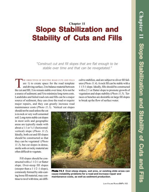
THE OBJECTIVES OF ROUTINE ROAD CUTS AND FILLS<br />
are 1) to create space for the road template<br />
and driving surface; 2) to balance material between<br />
the cut and fill; 3) to remain stable over time; 4) to not be<br />
a source of sediment; and 5) to minimize long-term costs.<br />
Landslides and failed road cuts and fills can be a major<br />
source of sediment, they can close the road or require<br />
major repairs, and they can greatly increase road<br />
maintenance costs (Photo <strong>11</strong>.1). Vertical cut slopes<br />
should not be used unless the cut<br />
is in rock or very well cemented<br />
soil. Long-term stable cut slopes<br />
in most soils and geographic<br />
areas are typically made with<br />
about a 1:1 or ¾:1 (horizontal:<br />
vertical) slope (Photo <strong>11</strong>.2).<br />
Ideally, both cut and fill slopes<br />
should be constructed so that<br />
they can be vegetated (Photo<br />
<strong>11</strong>.3), but cut slopes in dense,<br />
sterile soils or rocky material are<br />
often difficult to vegetate.<br />
Fill slopes should be constructed<br />
with a 1 1/2:1 or flatter<br />
slope. Over-steep fill slopes<br />
(steeper than a 1 1/2 :1 slope),<br />
commonly formed by side-casting<br />
loose fill material, may continue<br />
to ravel with time, are diffi-<br />
“Construct cut and fill slopes that are flat enough to be<br />
stable over time and that can be revegetated.”<br />
cult to stabilize, and are subject to sliver fill failures<br />
(Photo <strong>11</strong>.4). A rock fill can be stable with a<br />
1 1/3:1 slope. Ideally, fills should be constructed<br />
with a 2:1 or flatter slope to promote growth of<br />
vegetation and slope stability (Photo <strong>11</strong>.5). Terraces<br />
or benches are desirable on large fill slopes<br />
to break up the flow of surface water.<br />
Photo <strong>11</strong>.1 Over-steep slopes, wet ares, or existing slide areas can<br />
cause instability problems for a road and increase repair and<br />
maintanance costs, as well as sediment production.<br />
LOW-VOLUME ROADS BMPS:103<br />
Chapter <strong>11</strong> Slope Stabiliza<br />
Sta<br />
bilization and Stability Sta<br />
of Cuts and Fills
Photo <strong>11</strong>.2 Construct cut<br />
slopes at a 3/4:1 or flatter slope<br />
in most soils for long-term<br />
stability. In well-cemented soils<br />
and rock, a 1/4:1 cut clope will<br />
usually be stable.<br />
Photo <strong>11</strong>.3 A well-stabilized cut<br />
slope, with about a 1:1 slope, that<br />
is well covered with vegetation.<br />
Photo <strong>11</strong>.4 Avoid loose, oversteep<br />
fill slopes (steeper than 1 1/<br />
5:1), particularly along streams<br />
and at drainage crossings.<br />
LOW-VOLUME ROADS BMPS: 104
Table<strong>11</strong>.1 presents a range of<br />
commonly used cut and fill slope ratios<br />
appropriate for the soil and rock<br />
types described. Also Figure <strong>11</strong>.1<br />
and Figure <strong>11</strong>.2 show typical cut<br />
slope and fill slope design options, respectively,<br />
for varying slope and site<br />
conditions. Note, however, that local<br />
conditions can vary greatly, so<br />
determination of stable slopes should<br />
be based upon local experience and<br />
judgment. Groundwater is the major<br />
cause of slope failures.<br />
Slope failures, or landslides, typically<br />
occur where a slope is oversteep,<br />
where fill material is not compacted,<br />
or where cuts in natural soils<br />
encounter groundwater or zones of<br />
weak material. Good road location<br />
can often avoid landslide areas and<br />
reduce slope failures. When failures<br />
do occur, the slide area should be stabilized<br />
by removing the slide material,<br />
flattening the slope, adding drainage,<br />
or using structures, as discussed<br />
below. Figure <strong>11</strong>.3 shows some of<br />
the common causes of slope failures<br />
along with common solutions. Designs<br />
are typically site specific and<br />
may require input from geotechnical<br />
engineers and engineering geologists.<br />
Failures that occur typically impact<br />
road operations and can be costly to<br />
repair. Failures near streams and<br />
channel crossings have an added risk<br />
of impact to water quality.<br />
A wide range of slope stabilization<br />
measures is available to the engineer<br />
to solve slope stability problems<br />
and cross an unstable area. In<br />
most excavation and embankment<br />
work, relatively flat slopes, good<br />
compaction, and adding needed<br />
drainage will typically eliminate routine<br />
instability problems (Photo<br />
<strong>11</strong>.6). Once a failure has occurred,<br />
Photo <strong>11</strong>.5 Construct fill slopes with a 1 1/2:1 or flatter slope (to<br />
promote vegetation growth) and stabilize the fill slope surface. Use<br />
benches (terraces) on large fill slopes to intercept any flow of surface<br />
water.<br />
Table le <strong>11</strong>.1<br />
COMMON STABLE SLOPE RATIOS<br />
FOR VARYING SOIL/ROCK CONDITIONS<br />
Soil/Rock Condition<br />
Slope Ratio (Hor:Vert)<br />
Most rock ¼:1 to ½:1<br />
Very well cemented soils ¼:1 to ½:1<br />
Most in-place soils ¾:1 to 1:1<br />
Very fractured rock 1:1 to 1 ½:1<br />
Loose coarse granular soils 1 ½:1<br />
Heavy clay soils 2:1 to 3:1<br />
Soft clay rich zones or 2:1 to 3:1<br />
wet seepage areas<br />
Fills of most soils 1 ½:1 to 2:1<br />
Fills of hard, angular rock 1 1/3:1<br />
Low cuts and fills (
Figur<br />
igure <strong>11</strong>.1 Cut slope design options.<br />
a. Balanced Cut and Fill<br />
Natural Ground<br />
Use a Balanced Cut and Fill<br />
Section for Most Construction<br />
on Hill Slopes.<br />
2:1 Typical<br />
Fill<br />
Road<br />
Cut<br />
0-60% Ground slopes<br />
Typical Cut Slopes in<br />
Most Soils ¾:1 to 1:1<br />
Typical Rock<br />
Cut Slopes<br />
¼:1 to ½:1<br />
60% +<br />
b. Full Bench Cut<br />
¾:1<br />
1:1<br />
½:1<br />
¼:1<br />
Road<br />
Use Full Bench Cuts When the<br />
Ground Slopes Exceed +/- 60%<br />
0 - 60%<br />
c. Through Cut<br />
Low Cut<br />
Can be Steep<br />
or Flatter<br />
2:1<br />
Road<br />
¾:1 to 1:1<br />
High Cut<br />
Typically Steeper<br />
Where Stable<br />
LOW-VOLUME ROADS BMPS: 106
Figur<br />
igure <strong>11</strong>.2 Fill slope design options<br />
a. Typical Fill Natural ground<br />
Slash<br />
Typically place fill on<br />
a 2:1 or flatter slope.<br />
Road<br />
Scarify and remove<br />
organic material<br />
0-40%<br />
Ground slope<br />
Note: Side-cast fill material<br />
only on gentle slopes, away<br />
from streams.<br />
b. Benched Slope Fill with<br />
Layer Placement<br />
1 1/2:1 Typical<br />
Road<br />
40-60%<br />
Fill material placed in layers . Use<br />
lifts 15-30 cm thick. Compact to<br />
specified density or wheel roll<br />
each layer.<br />
Slash<br />
Note: When possible, use a 2:1<br />
or flatter fill slope to promote<br />
revegetation.<br />
On ground where slopes exceed 40 - 45%, construct<br />
benches +/- 3 m wide or wide enough<br />
for excavation and compaction equipment.<br />
c. Reinforced Fill<br />
Road<br />
Typically<br />
60% +<br />
Reinforced fills are used on<br />
steep ground as an<br />
alternative to retaining<br />
structures. The 1:1 (Oversteep)<br />
face usually requires<br />
stabilization.<br />
1:1<br />
Drain<br />
Geogrid or geotextile<br />
reinforcement layers<br />
d. Through Fill<br />
Long fill<br />
slope<br />
2:1<br />
Road<br />
Short fill<br />
slope<br />
3:1<br />
0-40%<br />
LOW-VOLUME ROADS BMPS:107
Figur<br />
igure <strong>11</strong>.3 Slope problems and solutions with stabilization measures.<br />
The Problem<br />
Oversteep (near<br />
vertical) cutslope<br />
Cut failure<br />
Uncontrolled<br />
water<br />
Fill failure in<br />
oversteep or<br />
uncompacted<br />
fill material<br />
Loose<br />
sidecast fill<br />
on a steep<br />
slope<br />
Solutions<br />
Cut slope laid back<br />
to a stable angle<br />
Cut slope<br />
failure<br />
Original<br />
oversteepened<br />
slope<br />
1:1<br />
Rock buttress<br />
with underdrain<br />
Note: This drawing shows a<br />
variety of slope stabilization<br />
measures which can be used to<br />
stabilize cuts and fills.<br />
LOW-VOLUME ROADS BMPS: 108<br />
Potential fill<br />
failure surface<br />
Fill compacted in<br />
15-30 cm thick layers<br />
2:1<br />
Subdrainage<br />
Vegetation on fill<br />
slope surface,<br />
preferably 2:1 or<br />
flatter<br />
Retaining structure
Photo <strong>11</strong>.6 Simple hand compaction behind a low rock wall. Compaction<br />
is important behind any retaining structure or fill. It can be<br />
achieved by hand or, preferably, using equipment such as a wacker or<br />
small compactor.<br />
the most appropriate stabilization<br />
measure will depend on site-specific<br />
conditions such as the size of the slide,<br />
soil type, road use, alignment constraints,<br />
and the cause of the failure.<br />
Here are a range of common slope<br />
stabilization options appropriate for<br />
low-volume roads, presented roughly<br />
from simplest and least expensive, to<br />
the most complex and expensive:<br />
• Install slope drainage such as<br />
deep cutoff trenches or dewater<br />
with horizontal drains.<br />
• Design and construct buttresses<br />
(Photo <strong>11</strong>.7), retaining structures,<br />
or rock anchors.<br />
Retaining structures are relatively<br />
expensive but necessary in steep areas<br />
to gain roadway space or to support<br />
the roadbed on a steep slope,<br />
rather than make a large cut into the<br />
hillside. They can also be used for<br />
slope stabilization. Figure <strong>11</strong>.4 (a<br />
and b) presents information on common<br />
types of retaining walls and<br />
simple design criteria for rock walls,<br />
where the base width is commonly<br />
0.7 times the wall height (Photo<br />
<strong>11</strong>.8). Figure <strong>11</strong>.4c presents common<br />
gabion gravity wall designs and<br />
basket configurations for varying wall<br />
heights. Gabion structures are very<br />
commonly used for walls up to 6<br />
meters high, particularly because they<br />
use locally available rock and are labor<br />
intensive (Photo <strong>11</strong>.9).<br />
For low to high walls in many<br />
geographic areas today, Mechanically<br />
Stabilized Earth (MSE), or “Reinforced<br />
Soil” structures are the least<br />
expensive type of wall available. They<br />
are simple to build, and often they can<br />
use on-site granular backfill material.<br />
They are commonly constructed using<br />
layers of geotextile or welded wire<br />
placed in lifts 15 to 45 cm apart in<br />
the soil, thus adding tensile reinforce-<br />
• Simply remove the slide material.<br />
• Ramp over or align the road<br />
around the slide.<br />
• Revegetate the slope and add<br />
spot stabilization (See Photo<br />
13.10).<br />
• Flatten or reconstruct the slope.<br />
• Raise or lower the road level to<br />
buttress the cut or remove<br />
weight from the slide, respectively.<br />
• Relocate the road to a new<br />
stable location.<br />
Photo <strong>11</strong>.7 A drained rock buttress can be used to stabilize a cut<br />
slope failure area.<br />
LOW-VOLUME ROADS BMPS:109
Figure <strong>11</strong>.4 Construction of various types of retaining structures. (Adapted from Gray & Leiser, 1982)<br />
Keys<br />
Brick or Masonry<br />
Rock<br />
Concrete<br />
Gravity Walls<br />
Reinforced Concrete<br />
Concrete with Counterforts<br />
Road<br />
Piles<br />
Counterfort<br />
“H" Piles<br />
Stretcher<br />
Headers<br />
Gabion Wall<br />
Facing<br />
Reinforced Soil<br />
Crib Wall<br />
a. Common Types of Retaining Structures.<br />
Reinforced Soil Wall<br />
High Rock Wall<br />
Configuration<br />
½ : 1 to<br />
Vertical<br />
Width<br />
(W)<br />
Hmax = 5 meters<br />
2<br />
1<br />
Aggregate<br />
Fill<br />
Rock<br />
For<br />
H = 0.5 m, W = 0.2 m<br />
H = 1.0 m, W = 0.4 m<br />
H = 1.5 m, W = 0.7 m<br />
H = 2.0 m, W = 1.0 m<br />
Rock<br />
± 70 cm<br />
Height<br />
(H)<br />
0.3-0.5 m<br />
0.7 H<br />
Low Rock Wall Configuration<br />
b. Typical Rock Wall Construction.<br />
LOW-VOLUME ROADS BMPS: <strong>11</strong>0
Figure <strong>11</strong>.4 Continued. (Adapted from Gray & Leiser, 1982)<br />
1<br />
1<br />
2<br />
No of<br />
levels<br />
H<br />
B<br />
No. of<br />
gabions<br />
(per<br />
width)<br />
H<br />
6<br />
3<br />
1 3' 3" 3' 3" 1<br />
4<br />
5<br />
6<br />
2 6' 6" 4' 3" <strong>11</strong>/2<br />
3 9' 9" 5' 3" 2<br />
4 13' 1" 6' 6" 2<br />
5 16' 4" 8' 2" 21/2<br />
B<br />
6 19' 7" 9' 9" 3<br />
Flat Backfill (smooth face)<br />
20"<br />
1<br />
1<br />
2<br />
1.5<br />
β = 34°<br />
No. of<br />
levels<br />
H<br />
B<br />
No. of<br />
gabions<br />
(per<br />
width)<br />
1 3' 3" 3' 3" 1<br />
H<br />
3<br />
4<br />
5<br />
6<br />
2 6' 6" 4' <strong>11</strong>" <strong>11</strong>/2<br />
3 9' 9" 6' 6" 2<br />
4 13' 1" 8' 2" 21/2<br />
5 16' 4" 9' 9" 3<br />
B<br />
6 19' 7" <strong>11</strong>' 5" 31/2<br />
Fill at 1 1/2:1 (face with steps)<br />
Note: Loading conditions are for silty sand to sand and gravel back fill. For finer or clay rich soils,<br />
earth pressure on the wall will increase and the wall base width (B) will have to increase for each<br />
height. Backfill weight = <strong>11</strong>0 pcf. (1.8 Tons/m 3 ) (1,762 kg/m 3 )<br />
- Safe against overturning for soils with a minimum bearing capacity of 2 Tons/foot 2 (19,500 kg/m 2 )<br />
- For flat or sloping backfills, either a flat or stepped face may be used.<br />
b. Standard design for Gabion Retaining Structures up to 20 feet in height (6 meters) with<br />
flat or sloping backfill.<br />
LOW-VOLUME ROADS BMPS:<strong>11</strong>1
ment to the soil (see Figure 6.3e).<br />
Driven “H” piles or sheet piles, with<br />
or without tiebacks, are relatively<br />
expensive but are often the most environmentally<br />
acceptable type of wall.<br />
They cause less site disturbance than<br />
gravity or MSE structures that require<br />
a large foundation excavation. Most<br />
types of retaining structures and designs<br />
provided by manufacturers are<br />
internally stable for the specified use,<br />
site conditions, and height. Most wall<br />
failures occur due to foundation failure.<br />
Thus structures must be placed<br />
on a good foundation, such as bedrock<br />
or firm, in-place soil.<br />
PRACTICES TO<br />
AVOID<br />
• Constructing vertical cut<br />
slopes (except in very well<br />
cemented soils and rock).<br />
• Road locations and construction<br />
practices where the toe of<br />
the fill ends up in the creek. Do<br />
not use side-cast fill placement<br />
methods on steep slopes next<br />
to streams.<br />
• Placing fills or “side-casting”<br />
materials on natural ground<br />
slopes steeper than 60%.<br />
Photo <strong>11</strong>.8 Use physical slope stabilization methods, such as retaining<br />
walls, reinforced fills, or rock buttresses where necessary in areas<br />
of space limitation on steep slopes.<br />
• Road locations in areas of<br />
known instability.<br />
• Leaving cut slopes and, particularly,<br />
fill slopes barren and<br />
exposed to erosion.<br />
LOW-VOLUME ROADS BMPS: <strong>11</strong>2<br />
Photo <strong>11</strong>.9 Gabions are a commonly used type of low gravity retaining<br />
structure because they use locally available rock and are relatively<br />
inexpensive.
• Use balanced cut and fill<br />
construction in most terrain to<br />
minimize earthwork (Figure<br />
<strong>11</strong>.1a).<br />
• On steep ground (>60%<br />
slope) use full bench construction.<br />
Consider constructing<br />
a narrow, single lane road<br />
with inter-visible turnouts to<br />
minimize excavation (Figure<br />
<strong>11</strong>.1b).<br />
• Construct cut slopes in most<br />
soils using a cut slope ratio of<br />
3/4:1 to 1:1 (horizontal:<br />
vertical) (Figure <strong>11</strong>.1). Use<br />
flatter cut slopes in coarse<br />
granular and unconsolidated<br />
soils, in wet areas, and in soft<br />
or clay-rich soils. Use relatively<br />
flat cut slopes (2:1 or<br />
flatter) for low (
Photo <strong>11</strong>.10 A road fill failure in<br />
steep terrain which now needs<br />
either a retaining structure or a<br />
large road cut around the failure.<br />
Photo <strong>11</strong>.<strong>11</strong> A tire-faced,<br />
mechanically stabilized earth<br />
(MSE) retaining wall, with layers<br />
of geotextile reinforcement,<br />
being used to gain road width in a<br />
fill failure area. MSE (reinforced<br />
soil) structures are often the<br />
least expensive retaining<br />
structure available. Welded wire<br />
MSE walls are also commonly<br />
used.<br />
Photo <strong>11</strong>.12 A gabion retaining<br />
structure which will fail soon due<br />
to lack of a suitable foundation.<br />
All retaining structures, either<br />
mechanically stabilized earth<br />
(MSE) walls or gravity walls,<br />
require a good foundation.<br />
LOW-VOLUME ROADS BMPS: <strong>11</strong>4