BM 100 A Reflex-Radar
BM 100 A Reflex-Radar
BM 100 A Reflex-Radar

Create successful ePaper yourself
Turn your PDF publications into a flip-book with our unique Google optimized e-Paper software.
© KROHNE 01/2004 7.02261.22.00<br />
GR<br />
Handbook<br />
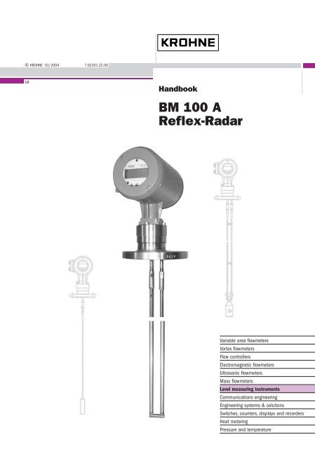
<strong>BM</strong> <strong>100</strong> A<br />
<strong>Reflex</strong>-<strong>Radar</strong><br />
Variable area flowmeters<br />
Vortex flowmeters<br />
Flow controllers<br />
Electromagnetic flowmeters<br />
Ultrasonic flowmeters<br />
Mass flowmeters<br />
Level measuring instruments<br />
Communications engineering<br />
Engineering systems & solutions<br />
Switches, counters, displays and recorders<br />
Heat metering<br />
Pressure and temperature
Table of contents<br />
General advice on safety.................................................................................................................4<br />
Range of application........................................................................................................................4<br />
Items supplied..................................................................................................................................4<br />
Documentation supplied.................................................................................................................4<br />
Principal gauge components..........................................................................................................5<br />
Product liability and warranty.........................................................................................................6<br />
1 Mechanical installation .....................................................................................................7<br />
1.1 Handling and storage...........................................................................................................7<br />
1.1.1 Avoiding blows.....................................................................................................................7<br />
1.1.2 Avoiding bending .................................................................................................................7<br />
1.1.3 Avoiding cable kinks or fraying ............................................................................................7<br />
1.2 Installation restrictions .........................................................................................................8<br />
1.3 Mounting on a tank ..............................................................................................................8<br />
1.3.1 Installation instructions: General notes ................................................................................8<br />
1.3.2 Installation instructions: Nozzle............................................................................................8<br />
1.3.3 Installation instructions: Gauge - all applications ...............................................................12<br />
1.3.4 Specific installation instructions: gauge - liquid applications..............................................14<br />
1.3.5 Specific installation instructions: gauge - solid applications...............................................15<br />
2 Electrical Connections ....................................................................................................17<br />
2.1 Insulation rating .................................................................................................................17<br />
2.2 Electrical installation instructions .......................................................................................18<br />
2.2.1 Wiring general notes..........................................................................................................18<br />
2.2.2 Wiring connections ............................................................................................................19<br />
3 User Interface...................................................................................................................23<br />
3.1 Power On and self-test mode ............................................................................................23<br />
3.2 Local user interface ...........................................................................................................23<br />
3.3 Status Markers...................................................................................................................24<br />
3.4 Parameter Settings ............................................................................................................24<br />
3.4.1 General Information ...........................................................................................................24<br />
3.4.2 Configuration Procedure....................................................................................................24<br />
3.4.3 Quick Configuration: configuration examples ....................................................................26<br />
3.4.4 Network Configuration – digital outputs and gauge identification : RS 485, multi-drop......32<br />
3.4.5 Summary of User Functions ..............................................................................................33<br />
3.4.6 <strong>BM</strong><strong>100</strong>A TDR level meter characteristics ..........................................................................39<br />
4 Service and maintenance................................................................................................45<br />
4.1 Test Functions in the user menu........................................................................................45<br />
4.2 Troubleshooting.................................................................................................................45<br />
4.2.1 Parameter errors................................................................................................................45<br />
4.2.2 Basic Servicing – Replacing fuses and the electronics chassis.........................................46<br />
4.3 Fault clearing .....................................................................................................................49<br />
5 Ordering spare parts .......................................................................................................50<br />
2 Handbook <strong>BM</strong> <strong>100</strong> A
6 Technical data..................................................................................................................52<br />
6.1 Technical Data................................................................................................................... 52<br />
6.2 <strong>BM</strong> <strong>100</strong> A Equipment Architecture..................................................................................... 54<br />
6.2.1 <strong>BM</strong> <strong>100</strong> A mechanical options...................................................................................... 54<br />
6.2.2 Definition of terms.............................................................................................................. 56<br />
6.2.3 Probe measurement limits................................................................................................. 57<br />
6.3 Gauge dimensions............................................................................................................. 58<br />
7 Measuring Principle ........................................................................................................ 59<br />
7.1 Direct mode ....................................................................................................................... 60<br />
8 Certificates and Approvals ............................................................................................. 61<br />
9 PC STAR software installation and operation instructions ......................................... 62<br />
9.1 Software Installation .......................................................................................................... 62<br />
9.2 PC-STAR Software history ................................................................................................ 62<br />
9.3 Setting up the gauge before connecting with the software ................................................ 63<br />
9.4 PCSTAR Functions ........................................................................................................... 63<br />
9.4.1 F1 Help:............................................................................................................................. 63<br />
9.4.2 F2 Connection: ..................................................................................................................64<br />
9.4.3 F3 Exit: .............................................................................................................................. 73<br />
9.4.4 F4 Serial (parameters):...................................................................................................... 73<br />
9.4.5 F5 Record Reading ........................................................................................................... 74<br />
9.4.6 F7 Configuration................................................................................................................76<br />
9.4.7 F9 Colors........................................................................................................................... 77<br />
9.4.8 Other important PCSTAR functions................................................................................... 77<br />
Appendix A: Returning a device for testing or repair to KROHNE............................................ 78<br />
Appendix B: <strong>BM</strong> <strong>100</strong> A Level Gauge Configuration Record ...................................................... 79<br />
Appendix C: <strong>BM</strong> <strong>100</strong> A – CE Declaration of Conformity............................................................. 80<br />
Handbook <strong>BM</strong> <strong>100</strong> A 3
General advice on safety<br />
The device will normally weigh between approx. 11 kg / 25 lb and 35kg / 77 lb. Carry the<br />
device using two people, lifting it by the flange holes and supporting the probe. Lifting<br />
gear may also be used but no attempt should be made to lift the device by the probe.<br />
Range of application<br />
The <strong>BM</strong> <strong>100</strong> A TDR Level gauge measures the level and volume of liquids and liquid gases. It can<br />
also measure the level and volume of pastes, powders, slurries and granular products.<br />
The <strong>BM</strong> <strong>100</strong> A also permits continuous and simultaneous measurement of liquid level and interface<br />
of two liquids.<br />
For the storage of volatile products, such as water and carbon disulphide tanks, the <strong>BM</strong> <strong>100</strong> A can<br />
also be equipped with a probe (type G) to measure the interface with a top mounted probe: this<br />
avoids the resultant safety issues of installing a gauge under the tank.<br />
Items supplied<br />
• signal converter connected to a cable, coaxial or rod signal guidance probe, as per order.<br />
Optional: remote extension with wall support, sunshade (with fastening material in each case)<br />
• bar magnet for operator control / parameter assignment (only for version with local display)<br />
• wrench for the covers<br />
Documentation supplied<br />
The following documentation will be included with the instrument:<br />
• installation and operating instructions (this manual), and handbook.<br />
• approval documents, unless reproduced in the installation and operating instructions.<br />
4 Handbook <strong>BM</strong> <strong>100</strong> A
Principal gauge components<br />
Non-Ex version<br />
Ex Version<br />
1 Cable entry (output)<br />
2 Cable entry (power supply)<br />
3 Local user interface (display screen, buttons and magnetically-actuated hall sensors)<br />
4 Nameplate (see diagram on the following page)<br />
5 Flange<br />
6 Single cable probe<br />
7 Counterweight<br />
8 Twin cable probe<br />
9 Spacer<br />
10 Short-circuit<br />
11 Equipotential bonding system connection (Ex)<br />
12 Isolating chamber – separates electronics housing from hazardous products<br />
13 Pressure release plug (1 bar or 14.5 psi limit) and vent<br />
14 Coaxial probe<br />
Handbook <strong>BM</strong> <strong>100</strong> A 5
Standard nameplate<br />
Product liability and warranty<br />
The <strong>BM</strong> <strong>100</strong> A TDR level gauge is designed solely for measuring the distance, level, interface and<br />
volume of liquids, pastes, slurries, solids and particulate materials.<br />
The <strong>BM</strong> <strong>100</strong> A TDR level gauge does not form part of an overfill protection system as defined in<br />
WHG nor is it concerned by the Pressure Equipment Directive (PED) 97/23/EC.<br />
Special codes and regulations apply to its use in hazardous areas.<br />
Responsibility as to suitability and intended use of these level gauges rests solely with the user.<br />
Improper installation and operation of our level gauges may lead to loss of warranty.<br />
In addition, the "General conditions of sale", found on the back of the invoice and forming the basis<br />
of the purchasing contract, are applicable.<br />
If you need to return the level gauge to the manufacturer or supplier, please refer to the information<br />
given in appendix A.<br />
6 Handbook <strong>BM</strong> <strong>100</strong> A
1 Mechanical installation<br />
1.1 Handling and storage<br />
Caution :<br />
The probe is a critical gauge component.<br />
Do not damage– Handle with care!!!<br />
1.1.1 Avoiding blows<br />
Avoid hard blows, impacts and jolts when handling the <strong>BM</strong><strong>100</strong>A.<br />
Caution : fragile electronics<br />
1.1.2 Avoiding bending<br />
Rod/ Coaxial probes: support the probe to avoid bending.<br />
Support probe here<br />
1.1.3 Avoiding cable kinks or fraying<br />
Do not coil the cable less than 400 mm / 16’’ in diameter. Cable kinks or fraying will cause<br />
measurement errors.<br />
Handbook <strong>BM</strong> <strong>100</strong> A 7
1.2 Installation restrictions<br />
Hazardous-duty systems (Ex, FM…)<br />
• refer to the supplementary instructions for gauges approved for use in hazardous locations<br />
before installation.<br />
• check that the flange, gasket and probe materials are compatible with the product. Read the<br />
information given on the converter nameplate, the flange markings and specifications in the<br />
approval certificates.<br />
1.3 Mounting on a tank<br />
1.3.1 Installation instructions: General notes<br />
The fitter should give some thought to tank fittings and tank shape:<br />
• nozzle position in relation to the tank walls and other objects inside the tanks<br />
(Warning : this free area will depend on the probe type selected: refer to later on in this section)<br />
• type of tank roof , i.e. floating, concrete, integral, etc; and base, i.e. conical,etc.<br />
1.3.2 Installation instructions: Nozzle<br />
Nozzle height<br />
Recommendation (especially for single probes and powder applications):<br />
Do not fit a nozzle longer than its diameter.<br />
h ≤ Ød<br />
, where h = nozzle height and d = nozzle diameter.<br />
Contact KROHNE if this relationship cannot be respected.<br />
8 Handbook <strong>BM</strong> <strong>100</strong> A
Nozzles extending into tank<br />
Caution:<br />
Do not use nozzles that extend into the tank. This will block the emitted pulse.<br />
Process connection<br />
For the gauge to make accurate measurements:<br />
• the tank process connection must be level.<br />
• ensure a good fit with the gauge process connection<br />
• the tank roof should not deform under the weight of the gauge<br />
Objects (discontinuities) inside the tank that influence the probe EM (electromagnetic) field<br />
Install the process connection far from protruding objects such as:<br />
• heating tubes<br />
• sudden changes in tank cross-section<br />
• tank wall reinforcements and beams,<br />
• weld lines and dip-stick pipes, etc...<br />
Refer to the figure at the top of the following page.<br />
TDR gauges generate electromagnetic fields when a measurement pulse is emitted. This field is<br />
affected by any nearby discontinuities and these will weaken and potentially block the emitted pulse.<br />
A minimum distance is recommended depending on the probe type to be installed. See the table on<br />
the next page for recommended free space dimensions.<br />
Alternatively, the fitter may use a reference chamber or stilling well. However, the chamber walls<br />
must be smooth (i.e. no visible weld lines), straight and vertical to maintain the pulse strength and<br />
gauge accuracy.<br />
For clean applications only :<br />
Coaxial (type D) probes may be used close to or touching objects or walls as the EM field generated<br />
by the probe is contained within the probe’s outer sheath (refer also to the EM field sizes given in<br />
the figures on the next page).<br />
Handbook <strong>BM</strong> <strong>100</strong> A 9
1 Agitator<br />
2 Support beam perpendicular to the pulse<br />
direction<br />
3 Abrupt changes in tank cross section<br />
4 Heating tubes<br />
5 Alternative solution: reference chamber -<br />
electromagnetic field is contained within<br />
chamber.<br />
6 Gauge electromagnetic field :<br />
Any intruding metallic object will be<br />
detected in this zone if perpendicular to<br />
the emitted pulse direction.<br />
= Do not fit the process connection near to these objects.<br />
Probe Type<br />
Recommended minimum distance of probe from<br />
objects inside the tank in millimetres (inches)<br />
Single (types F, H and K) 300 (12)<br />
Twin (types A, B, G and L) <strong>100</strong> (4)<br />
Coaxial (type D) 0 (0)<br />
Electromagnetic field shape around probe, by type (not to scale)<br />
Single (types F, H and K) Twin (types A, B, G and L) Coaxial (type D)<br />
No beam angle for any probe type.<br />
10 Handbook <strong>BM</strong> <strong>100</strong> A
Process connection and entry pipe<br />
Caution:<br />
Do not put the nozzle close to the entry pipe. Pouring the product directly onto the<br />
probe will give false readings. Install deflector plate if impossible to distance gauge<br />
from entry pipe.<br />
Stilling wells<br />
Tanks with floating roofs for petro-chemical applications: Use a stilling well.<br />
1<br />
Stilling well<br />
2<br />
Tank<br />
3 Floating roof<br />
4 Product (petroleum applications)<br />
5 Well fixed to tank base (no roof<br />
deformation)<br />
6 Sediment<br />
Handbook <strong>BM</strong> <strong>100</strong> A 11
1.3.3 Installation instructions: Gauge - all applications<br />
<strong>BM</strong><strong>100</strong> A gauges are designed to be mounted on a suitable process connection on a tank or sump.<br />
Install the gauge using two people to avoid damaging the probe. Support the housing and the probe.<br />
Installation of single and twin cable probe level meters<br />
1<br />
2<br />
Caution :<br />
Do not over-bend<br />
probe!<br />
Inserting the probe:<br />
hold more than one<br />
metre above the<br />
opening to avoid cable<br />
bending.<br />
Outdoor sites<br />
Fit a sunshade on the gauge for open-air installations: this is supplied on demand. The ambient<br />
temperature limits of the gauge are given below.<br />
12 Handbook <strong>BM</strong> <strong>100</strong> A
Cable probes: entanglement and straightness<br />
The cable must be straight once inserted into the tank. The cable counterweight should not touch<br />
the bottom of the tank. The cable must be far from other objects (e.g. mixers) to avoid entanglement.<br />
Rigid length of single and twin cable probes<br />
Cable diameter Rigid length<br />
Single cable<br />
Ø4mm or 0.15” 145mm or 5¾”<br />
Ø8mm or 0.3” 200mm or 8”<br />
Twin cable<br />
Ø4mm or 0.15” 145mm or 5¾”<br />
Ø6mm or 0.24” 145mm or 5¾”<br />
Handbook <strong>BM</strong> <strong>100</strong> A 13
1.3.4 Specific installation instructions: gauge - liquid applications<br />
Probe bending in agitated products: recommended solutions<br />
Probe (Type) Supports and fastenings Stilling well installation*<br />
Twin rod (A) Weld a 45mm / 1.8” internal diameter tube on<br />
the bottom of the vessel then insert the<br />
probe.<br />
Possible. On-site calibration may<br />
be required to maintain accuracy.<br />
Repeatability is unaffected.<br />
Twin cable (L)<br />
Single rod (F)<br />
Single cable (H)<br />
Coaxial (D)<br />
Fit an anchor with an M10 x 1 (Ø4mm/0.16”<br />
cable) thread (i.e. spring ring or hook) to the<br />
counterweight*** CAUTION: 6 Nm / 4.4 lbf.ft<br />
maximum torque. This cable may also be<br />
ordered with a turnbuckle.<br />
Weld a 12mm / 0.5” internal diameter tube on<br />
the bottom of the vessel, insert the rod****.<br />
Fit an anchor with M10x1 (Ø4mm cable)<br />
thread underneath the counterweight : spring<br />
ring or hook. CAUTION: 4 Nm / 2.9 lbf.ft<br />
maximum torque. This cable may also be<br />
ordered with either a chuck or turnbuckle.<br />
Weld a 30-32mm / 1.2” internal diameter tube<br />
on the bottom of the vessel, insert the tube. A<br />
probe may be fixed with braces.<br />
* Reference (bypass) chamber or stilling well.<br />
** Spacers supplied by KROHNE.<br />
*** Threaded hole provided in base of counterweight.<br />
**** Contact KROHNE. A factory menu function may need to be changed.<br />
Possible. On-site calibration may<br />
be required to maintain accuracy.<br />
Repeatability is unaffected.<br />
Centring the probe is<br />
recommended. Contact KROHNE<br />
for more information.<br />
Possible. 50 mm / 2” minimum<br />
diameter chamber. Contact<br />
KROHNE for assistance.<br />
Possible. 50 mm / 2” diameter<br />
minimum. Contact KROHNE for<br />
assistance**.<br />
Unnecessary: probe unaffected<br />
by nearby objects.<br />
1 Turnbuckle<br />
2 Chuck for type H Ø4mm<br />
single cable probe<br />
3 Counterweight with threaded base<br />
4 Avoid play between tube and probe<br />
5 Hole in welded tube for drainage<br />
Anchoring twin rod and coaxial probes<br />
14 Handbook <strong>BM</strong> <strong>100</strong> A
1.3.5 Specific installation instructions: gauge - solid applications<br />
False readings:<br />
1 Do not let probe touch the side of the nozzle<br />
Conical silo nozzles, False readings and traction on the cable probes<br />
Caution<br />
2<br />
3<br />
High traction forces :<br />
We recommend that the probe should not be<br />
anchored to avoid excessive traction loads on<br />
the cable.<br />
Bending and traction:<br />
Position the connection on the roof at ½<br />
radius of the tank and with minimum nozzle<br />
height. This will avoid damage due to<br />
bending and traction during emptying.<br />
Traction forces during emptying cycles for powder applications<br />
Traction load is dependent upon the height and shape of the tank, product particle size & density,<br />
and the rate at which the tank is emptied. The table below gives the load at which cable probes will<br />
break.<br />
Cable maximum design loads, traction<br />
Probe<br />
Type K : Single cable Ø8 mm / Ø 0.3”<br />
Type B : Twin cable Ø6 mm / Ø 0.2”<br />
Maximum Load<br />
3.5 T / 7700 lb<br />
3.6 T / 7900 lb (1.8 T / 3950 lb per cable)<br />
Handbook <strong>BM</strong> <strong>100</strong> A 15
Traction on cable according to product (approximate value in metric tons)<br />
Probe Length / m (ft)<br />
Material Probe used 10 (32.8) 20 (65.6) 30 (98.4)<br />
Cement Single cable Ø8 / Ø0.3’’ 1.0 T / 2200 lb 2.0 T / 4410 lb 3.0 T / 6620 lb<br />
Flyash Single cable Ø8 / Ø0.3’’ 0.5 T / 1<strong>100</strong> lb 1.0 T / 2200 lb 1.5 T / 3300 lb<br />
Wheat Single cable Ø8 / Ø0.3’’ 0.3 T / 660 lb 0.6 T / 1320 lb 1.2 T / 2650 lb<br />
PE granules Twin cable Ø6 / Ø0.2’’ 0.2 T / 440lb 0.6 T / 1320 lb 1.0 T / 2200lb<br />
Electro static discharge (E.S.D.)<br />
<strong>BM</strong><strong>100</strong> Standard and Ex gauge electronics are normally shielded up to 16KV against E.S.D.*.<br />
*For non-Ex powder applications, <strong>BM</strong><strong>100</strong>A probes are protected up to 32 kV.<br />
Note:<br />
E.S.D. cannot be solved by <strong>BM</strong><strong>100</strong>A E.S.D. protection. It is the customer’s responsibility<br />
to avoid E.S.D. by grounding the tank, product and probe installation.<br />
1<br />
Danger of injury<br />
The probe may become electro<br />
statically-charged during<br />
operation; earth the probe by<br />
pushing it against tank wall with a<br />
suitably isolated tool just before<br />
touching it to avoid receiving a<br />
shock.<br />
2 Earth the entry pipe and product.<br />
Product deposits on the nozzle and probe<br />
Product build-up can occur under the nozzle: this may weaken the pulse. Avoid cavities that permit<br />
the build-up of deposits.<br />
Tank roof deformation<br />
Tank roofs should support loads of at least 3.5 tonnes / 7700lb for gauge installations using type K<br />
single cable probes and 3.6 tonnes / 7900 lb for gauge installations using type B twin cable probes<br />
without deformation.<br />
16 Handbook <strong>BM</strong> <strong>100</strong> A
2 Electrical Connections<br />
2.1 Insulation rating<br />
The gauge transmitter electrical insulation conforms to IEC 1010-1. Please note the information<br />
below concerning each rating category.<br />
Category Rating Comments<br />
Power supply<br />
overvoltage category<br />
III<br />
The gauge does not have an integrated switch or circuitbreakers.<br />
These elements must be installed in<br />
conformance to local regulations and EU Low Voltage<br />
Guidelines and to properly isolate the equipment when<br />
necessary. Note that this is not obligatory for instruments<br />
with 24 V power supply boards.<br />
4 to 6.3 A time lag fuses are recommended for external<br />
installation.<br />
Fuses must be installed on every electrical conductor for<br />
the system to conform to current regulations.<br />
Note that the active phase conductor, L, is protected by an<br />
internal fuse: the neutral conductor, N, is not.<br />
Output circuit overvoltage category II Fuses are unnecessary.<br />
Insulation contamination level 2 The contamination level refers to the protection of internal<br />
elements of the signal converter.<br />
Rated IP 67 (equivalent to NEMA 6-6P) against ingress of<br />
water and other foreign bodies.<br />
Protection class 1<br />
Note that the gauge can operate in contamination level 4<br />
conditions if installed correctly.<br />
Galvanic isolation of terminals<br />
The gauge conforms to the following standard and E.U. Directive:<br />
Standard/Directive<br />
EN (IEC) 61010-1<br />
73/23/EEC<br />
Description<br />
Safety requirements for electrical equipment for measurement, control and<br />
laboratory use (low tension)<br />
Council Directive of 19 February 1973 on the harmonisation of the laws of<br />
Member States relating to electrical equipment designed for use within<br />
certain voltage limits (low voltage) modified by Directive 93/68/EEC (art.13).<br />
The <strong>BM</strong> <strong>100</strong> A gauge outputs are galvanically isolated from the power supply and ground in<br />
accordance with the regulations given above. An external barrier is unnecessary.<br />
Handbook <strong>BM</strong> <strong>100</strong> A 17
2.2 Electrical installation instructions<br />
2.2.1 Wiring general notes<br />
Read these instructions carefully!<br />
Wiring must comply with any existing local regulations. Use appropriate wiring methods, conduits<br />
and fittings to maintain a NEMA 6-6P / IP 67 rating.<br />
1. Always disconnect the mains power supply before opening the housing,<br />
2. unscrew the terminal compartment using the special wrench provided,<br />
3. use the top cable entry port for the power supply (see “Principal gauge components”),<br />
4. use a metal cable gland for input power leads to minimise RFI (radio frequency interference) /<br />
EMI (electromagnetic interference) effects,<br />
5. use a reinforced cable for the outputs,<br />
6. do not cross or loop wires in the signal converter wiring box,<br />
7. do not kink cables close to the glands. Cover with a metallic sheath at this point if necessary,<br />
8. make U-bends in the cable to provide water with run-off points,<br />
9. earthing the device shall be done according to the local applicable installation standards (EN<br />
60079.14 in Europe),<br />
10. and make sure that the cover thread in the housing is well greased and the O-ring is in good<br />
condition before replacing the cover.<br />
Shutting off the power supply : non-hazardous zones<br />
Remember to disconnect the power supply before opening the housing.<br />
Shutting off the power supply : hazardous zones<br />
Wait before opening the housing cover. Refer to Supplementary Installation<br />
and Operating Instructions for the <strong>BM</strong><strong>100</strong> A/Ai KEMA 01 ATEX 1078X<br />
Gauge for the time required.<br />
18 Handbook <strong>BM</strong> <strong>100</strong> A
2.2.2 Wiring connections<br />
Open the signal converter housing rear cover, using the plastic wrench supplied. The terminal<br />
connections are labelled. The standard connections are shown below.<br />
Before starting to wire:<br />
• check that the power supply corresponds to the power board installed.<br />
• check which output option you have selected: this will be indicated on the underside of the rear<br />
housing cover and on the gauge nameplate.<br />
Terminal layout : non – Ex version<br />
X = Terminal not used<br />
(X) = Terminal not used except for RS485 outputs<br />
Ensuring a good contact and protection of wire strands<br />
Local regulations concerning electrical wiring must be followed and obeyed. If no details are<br />
given, we recommend :<br />
• crimped metal sheaths over the wire strands<br />
• power supply cables should be rated for at least 500 V, with a cable diameter of 0.5 to 1.5<br />
mm / 0.02” to 0.06” (non-Ex applications only).<br />
• the output current cable diameter should be from 0.5 to 0.75 mm / 0.02” to 0.03”<br />
PE Ground Terminal notes<br />
The internal earth connection shall be used according local applicable installation standards, in<br />
Europe the Low voltage Standard prescribes the connection of the yellow/green cable in case of<br />
230VAC.<br />
Handbook <strong>BM</strong> <strong>100</strong> A 19
Terminal layout : Ex version<br />
(X) = Terminal not used except for RS485 outputs<br />
Wiring the gauge for use in hazardous areas (Ex & FM)<br />
Use the correct wires and spade tags for terminal connections as specified in the Supplementary<br />
Installation and Operating Instructions for the <strong>BM</strong><strong>100</strong> A/Ai KEMA 01 ATEX 1078X Gauge.<br />
PE Ground Terminal notes<br />
The internal earth connection shall be used according local applicable installation standards, in<br />
Europe the Low voltage Standard prescribes the connection of the yellow/green cable in case of<br />
230VAC.<br />
Options, power supply<br />
The type of power supply to be used will be indicated on the gauge nameplate.<br />
1. <strong>100</strong> – 240V AC -15%/+10% ; Power output : 9VA<br />
2. 24 V AC/DC -15%/+10% ; Power output : 9VA<br />
20 Handbook <strong>BM</strong> <strong>100</strong> A
Options, output<br />
The output wires should be wired to the gauge terminals according to the type of output selected<br />
when the order was placed. The type of output supplied will be indicated on the gauge nameplate<br />
and a sticker on the inside of the housing rear cover. The principle output options are shown below:<br />
• 1 passive output: passive = external power source used for measurement output<br />
• 1 active output: active = internal power source used for measurement output<br />
• 2 passive outputs<br />
Handbook <strong>BM</strong> <strong>100</strong> A 21
• 1 RS 485 output<br />
with / without optional passive analogue current output for direct readings**<br />
• 1 PROFIBUS PA output *<br />
with / without optional passive analogue current output for direct readings**<br />
* <strong>BM</strong> <strong>100</strong> A device management: a GSD file providing a device communication features list is<br />
delivered with PROFIBUS PA-output devices.<br />
** must be specified in customer order.<br />
22 Handbook <strong>BM</strong> <strong>100</strong> A
3 User Interface<br />
The <strong>BM</strong><strong>100</strong>A may be configured and operated using a user interface set into the signal converter<br />
housing or a remote link. Remote links using PC STAR, KROHNE’s in-house developed software<br />
and Fieldbus remote links are given at the end of section 3.4.3.<br />
3.1 Power On and self-test mode<br />
The <strong>BM</strong><strong>100</strong>A automatically self-tests once connected to a<br />
power source. The screen readout shown on the left will be<br />
displayed. This test takes from 20 seconds to 1½ minutes to<br />
complete.<br />
The local display will then switch over to the operation mode<br />
display shown on the following page.<br />
Firmware release currently programmed into the EPROM<br />
(Electrically Programmable Read Only Memory)<br />
3.2 Local user interface<br />
The <strong>BM</strong><strong>100</strong>A Local user interface is simple to use. It has three push-buttons, three magneticallykeyed<br />
sensors for configuring the gauge without removing the front cover in hazardous zones and a<br />
three-line LCD (Liquid Crystal Display) screen at the front of the signal converter housing.<br />
1 ENTER Hall Sensor:<br />
Keyed using a bar magnet. As item 6.<br />
2 First Display Line:<br />
Operating mode- measurement value<br />
Configuration mode- function number<br />
3 Second Display Line:<br />
Operating mode- item measured and units<br />
Configuration mode- function definition<br />
4 UP Hall Sensor:<br />
Keyed using a bar magnet. As item 5.<br />
5 Press the UP push-button:<br />
• To increase the value of a selected digit<br />
• For password definition : code U or ↑<br />
6 Press the ENTER push-button:<br />
• To go back a step in the menu<br />
• To validate data entered<br />
• For password definition : code E or ↵<br />
7 Press the RIGHT push-button:<br />
• To enter configuration mode<br />
The display screen will go blank below • To move cursor right in configuration mode<br />
–20°C / -4°F but data can still be<br />
• For password definition : code R or →<br />
displayed if the instrument is<br />
connected to a computer with PC<br />
8 RIGHT Hall Sensor:<br />
Keyed using a bar magnet. As item 7.<br />
STAR or other remote link.<br />
9 Status Markers:<br />
See the next page for details.<br />
10 Key register symbol:<br />
Enter pressed<br />
↑ Up pressed<br />
→ Right pressed<br />
Handbook <strong>BM</strong> <strong>100</strong> A 23
3.3 Status Markers<br />
This line of numbers identifies six types of errors by means of a triangular indictor over the number<br />
concerned.<br />
Status marker Error / Status message Result and action<br />
number<br />
▼1 No initial pulse detected See section 4.3: Fault clearing.<br />
▼2 No level reflection detected See section 4.3: Fault clearing.<br />
▼3 Level measurement frozen Output and indication frozen; search initiated to<br />
redetect level : if no reflection is registered :<br />
Status marker 2 is activated.<br />
▼4 No interface reflection found See section 4.3: Fault clearing.<br />
▼5<br />
Interface measurement<br />
frozen<br />
Output and indication frozen; search initiated to<br />
redetect interface. If no reflection is found, Status<br />
marker 4 is activated.<br />
▼6<br />
Output communication failure Contact your local KROHNE Service Department.<br />
If the parameter 1.2.6 Error Display is configured to “YES” as explained in section 3.4.5,<br />
the complete display screen will flash when an error occurs.<br />
3.4 Parameter Settings<br />
3.4.1 General Information<br />
Your <strong>BM</strong><strong>100</strong> A has now been installed on the tank and the necessary electrical connections have<br />
been made. Once the power has been switched on, it may be necessary to configure the gauge to:<br />
• display the readings using the correct units and reference point (level / distance ),<br />
• change the measurement range,<br />
• give the instrument an address so that it may be integrated into a network,<br />
• display volume readings by programming and using a volume calibration table (strap table).<br />
We recommend that any changes to settings be noted on the configuration record supplied in<br />
appendix B, or recorded using PC-STAR, to enable KROHNE service personnel to provide a rapid<br />
response to any enquiries.<br />
3.4.2 Configuration Procedure<br />
The <strong>BM</strong><strong>100</strong> A starts up in operating mode displaying either information according to customer<br />
specifications or factory default values.<br />
The configuration mode (user menu) can be accessed and parameters modified by following the<br />
operator control concept summary below. Configuration procedure is described in more detail in<br />
section 3.4.3.<br />
Instruments may equally be configured individually using a remote display available in PC-STAR<br />
software for remote connections. Please refer to the PC-STAR on-line Help file for more details.<br />
A restricted-access factory menu is available for advanced configuration. Refer to the <strong>BM</strong><strong>100</strong> A<br />
Service Manual for further information.<br />
24 Handbook <strong>BM</strong> <strong>100</strong> A
Handbook <strong>BM</strong> <strong>100</strong> A 25
3.4.3 Quick Configuration: configuration examples<br />
The minimum functions (fct.) to be configured for a simple measurement are listed below:<br />
• 1.1.1 Tank Height<br />
• 1.2.1-6 Display Functions<br />
• 1.4.2-3 Entry Code 1 / Code 1<br />
• 1.3.1-4 Current Output 1 (& 2)<br />
• 1.7.1-2 Volume calibration*<br />
*For volume measurements<br />
Example procedures for each set of functions are given on the following pages. Each procedure is<br />
given in a series of steps in table form and begins from the Operating Mode.<br />
Useful definitions for quick configuration<br />
Typical gauge used for quick configuration examples<br />
Probe type:<br />
Tank height (Fct. 1.1.1):<br />
Hold distance (Fct. 1.1.2)<br />
Probe length, L 1 (Fct. 1.1.7):<br />
twin Ø4mm/0.16” cable probe, type L<br />
<strong>100</strong>00.00mm/33ft<br />
0.25m/10ft (see “probe measurement limits” in section 6.2.3 for<br />
the Ø4mm twin cable probe, type L)<br />
9.00m/29.5ft (Do not modify unless advised to)<br />
26 Handbook <strong>BM</strong> <strong>100</strong> A
Tank height<br />
Configuration Mode user function 1.1.1<br />
This function is usually either defined as true tank height or as factory configured probe length,<br />
L 1 if the former is not supplied by the customer in the order.<br />
Why change the tank height?<br />
• setting the parameter in Function 1.1.1 to L 1 avoids having a non-measurable zone<br />
underneath the probe where the measurement on the display freezes.<br />
• when setting up a measurement scale as explained on the following pages, this means that<br />
the level at the end of the probe will be taken as zero instead of the tank bottom.<br />
How tank height affects measurement when either Level or Distance is measured<br />
1 True tank height<br />
2 Measurable<br />
height (factory<br />
configured probe<br />
length, L 1 )<br />
3 Non-measurable<br />
zone<br />
4 With true tank<br />
height (1) set in<br />
Function 1.1.1 of<br />
the User’s menu.<br />
5 With factoryconfigured<br />
probe<br />
length, L 1 , set in<br />
Function 1.1.1. of<br />
the User’s menu.<br />
Example procedure 1:<br />
• to change true tank height (<strong>100</strong>00mm) to factory configured probe length, L 1 (9000mm) , and<br />
then save the new parameter. Refer to item 5 in the diagram above.<br />
Step Action Press buttons to<br />
finish step<br />
Information displayed at the end of<br />
each step<br />
1 Start from Operating n/a 6750<br />
Mode screen<br />
LEVEL mm<br />
2 Go to function (fct.) 1.1.1<br />
from Operating Mode<br />
→,→,→ Fct. 1.1.1<br />
TANK HEIGHT<br />
3 Enter function (current → <strong>100</strong>00.00<br />
value: <strong>100</strong>00mm)<br />
4 Modify value to 09000.00 ↑,↑,↑,↑,↑,↑,↑,↑,↑,<br />
09000.00<br />
(millimetres)<br />
→,↑,↑,↑,↑,↑,↑,↑,↑,<br />
↑<br />
5 Exit to Save function ↵,↵,↵,↵ STORE Yes<br />
6 Save & exit to Operating<br />
Mode<br />
↵ 5750<br />
LEVEL<br />
mm<br />
Handbook <strong>BM</strong> <strong>100</strong> A 27
How to configure displayed value and units<br />
User Sub-menu 1.2 - Display Functions<br />
These functions are used to choose the information to be displayed in operating mode:<br />
• the measurement function (distance, level, volume, etc.) and units (mm, ft., m3, etc.)<br />
• Display mode (1 (single) or 2 or more items in a repeating loop (cyclic mode))<br />
Example procedure 2:<br />
• to modify display mode from “single” to “cyclic” to configure a repeating loop displaying more<br />
than one piece of data,<br />
• to select Level and Distance and display each item for 5 seconds.<br />
Step Action Press buttons to<br />
finish step<br />
Information displayed at the end of<br />
each step<br />
1 Start from Operating Mode n/a 6750<br />
screen<br />
LEVEL mm<br />
2 Go to fct. 1.2.1 from the<br />
operating mode<br />
→,→,↑,→ Fct. 1.2.1<br />
DISP.MODE<br />
3 Enter function 1.2.1 →<br />
SINGL.MODE<br />
Display Mode (default<br />
value: SINGL.MODE)<br />
4 Modify value to<br />
↑<br />
CYCL.MODE<br />
CYCL.MODE<br />
5 Exit fct. 1.2.1data set field<br />
and go to fct. 1.2.2<br />
↵,↑ Fct. 1.2.2<br />
DISPL.ITEM<br />
6 Enter function 1.2.2<br />
(Display Item) data set field<br />
→<br />
LEVEL<br />
Default value: LEVEL<br />
7 Select “DISTANCE”. ↑↑ DISTANCE<br />
8 Press “RIGHT” to confirm →<br />
No<br />
or cancel data item to be<br />
added to display loop<br />
9 Press “UP” to confirm ↑<br />
Yes<br />
parameter<br />
10 Exit data set field to<br />
confirm. Go to to fct. 1.2.3<br />
↵,↵,↑ Fct. 1.2.3<br />
CYCLIC TIME<br />
11 Enter function 1.2.3 data<br />
set field (default value: 01).<br />
Change to 05 seconds.<br />
→,→,↑,↑,↑,↑ 05<br />
Sec<br />
12 Exit data set field, function,<br />
submenu and menu. Save<br />
new configuration and<br />
return to Operating Mode<br />
↵,↵,↵,↵,↵ 6750<br />
LEVEL mm<br />
The operator may display volume once the gauge is calibrated to measure volume in submenu<br />
1.7. Interface parameters may only be used if the gauge is factory-set for interface measurement.<br />
28 Handbook <strong>BM</strong> <strong>100</strong> A
How to protect gauge configuration<br />
User menu functions 1.4.2 Entry Code 1 & 1.4.3 Code 1<br />
These functions are used to activate the restricted-access code and lock the settings: these will be<br />
impossible to modify without entering the correct code. Do not lose this code!<br />
Example procedure 3A:<br />
• to activate access code function,<br />
• to enter new code and exit configuration mode.<br />
Step Action Press buttons to<br />
finish step<br />
Information displayed at the end<br />
of each step<br />
1 Start from Operating Mode n/a 6750<br />
screen<br />
LEVEL mm<br />
2 Go to function (fct.) 1.4.2 →,→,↑,↑,↑,→,→ Fct. 1.4.2<br />
ENTRY.CODE1<br />
3 Enter function data set field →<br />
(default value: No)<br />
No<br />
4 Select Yes to confirm activation ↑<br />
of access<br />
Yes<br />
code.<br />
4 Exit function and go to fct.<br />
1.4.3.<br />
Enter function 1.4.3 data set<br />
↵,↑<br />
→<br />
Fct. 1.4.3<br />
CODE 1<br />
CodE1<br />
5 field.<br />
---------<br />
Default: ( ↑↑↑↵↵↵→→→ )<br />
6 Enter new 9-keystroke code ↑,↑,↑,↑,↑,↑,↑,↑,↑ CodE1<br />
---------<br />
7 Re-enter new 9-keystroke code<br />
to confirm. Automatic exit from<br />
data set field to function.<br />
↑,↑,↑,↑,↑,↑,↑,↑,↑ Fct. 1.4.3<br />
CODE 1<br />
8 Exit function, submenu and<br />
menu. Save new<br />
configuration and return to<br />
Operating Mode.<br />
↵,↵,↵,↵ 6750<br />
LEVEL mm<br />
Example procedure 3B:<br />
• to re-enter the configuration mode from the Operating mode with the restricted-access<br />
function activated.<br />
9 Start from Operating Mode<br />
screen<br />
10 Press RIGHT button to enter<br />
Configuration Mode. Screen<br />
displays access code entry.<br />
11 Type 9-keystroke access code.<br />
User menus are now<br />
accessible. A typing error<br />
(impossible to delete incorrect<br />
keystroke) will quit the user<br />
back to the operating mode.<br />
n/a 6750<br />
LEVEL mm<br />
→ CodE 1<br />
---------<br />
↑,↑,↑,↑,↑,↑,↑,↑,↑ Fct. 1.0.0<br />
OPERATION<br />
Handbook <strong>BM</strong> <strong>100</strong> A 29
How to set an analogue current output scale<br />
User menu functions 1.3.1 to 1.3.4 (& 1.3.5 to 1.3.8 for a second analogue output)<br />
This set of functions allows users to set up a scale. The minimum (4mA) and maximum (20mA)<br />
values of an analogue current output should ideally lie within the device’s active measuring zone, as<br />
the display will freeze when the signal is lost.<br />
Refer to the measurement limits table for each probe type in the introduction. Refer also to the stqrt<br />
of section 3.4.3 for the advantages of changing tank height.<br />
Example procedure 4:<br />
• personalise a measurement scale<br />
• select “Level” as the current output parameter for the scale to be set up from the tank bottom<br />
• choose suitable minimum and maximum values for the scale.<br />
Step Action Press buttons to<br />
finish step<br />
Information displayed at<br />
the end of each step<br />
1 Start from Operating Mode screen n/a 6750<br />
LEVEL mm<br />
2 Go to Fct. 1.3.1 →,→,↑,↑,→ Fct. 1.3.1<br />
FUNCTION.I.1<br />
3 Enter data set field (current value: →<br />
DISTANCE<br />
Distance)<br />
4 Set to Level. ↑,↑,↑ LEVEL<br />
5 Exit data set level and go to fct. 1.3.2 ↵,↑ Fct. 1.3.2<br />
RANGE I 1<br />
6 Enter function (current value: 4 – 20<br />
mA) – to set the error output to 3.7 mA<br />
or 22 mA or having no error output.<br />
7 Modify value to 4 – 20 mA with error<br />
output at 22 mA.<br />
5 Exit data set field and go to fct. 1.3.3.<br />
Enter (current value: 00000.0 mm) – to<br />
set level that corresponds to the<br />
minimum current output 4 mA.<br />
6 Modify value to 0<strong>100</strong>0.0 mm (this sets<br />
the minimum point 1 metre above the<br />
tank bottom). The tank is considered<br />
to be empty below this point.<br />
7 Exit data set level and go to fct. 1.3.4.<br />
Enter function (current value: 14000.0<br />
mm) – to set level that corresponds to<br />
the max. current output 20 mA<br />
9 Change to 9600.0 (this sets the<br />
maximum below the top dead zone).<br />
The tank is considered to be full above<br />
this point<br />
10 Exit data set level, function, sub menu<br />
and menu. Save configuration and<br />
return to operating mode.<br />
30 Handbook <strong>BM</strong> <strong>100</strong> A<br />
→<br />
↑,↑<br />
↵,↑,→<br />
4 - 20<br />
4 – 20 /22=E<br />
00000.0<br />
mm<br />
→,↑ 0<strong>100</strong>0.0<br />
mm<br />
↵,↑,→ 14000.0<br />
mm<br />
↑,↑,↑,↑,↑,↑,↑,↑,↑,<br />
→,↑,↑,↑,↑,↑, →,↑,<br />
↑,↑,↑,↑<br />
9750.0<br />
mm<br />
↵,↵,↵,↵ 6750<br />
LEVEL mm<br />
Gauges with two current outputs<br />
Two outputs are required for displaying readings simultaneously for two separated products stored<br />
in the tank. Set up a scale using user functions 1.3.1 to 1.3.4 as shown above to measure level, then<br />
repeat the procedure for interface measurement using user functions 1.3.5 to 1.3.8. Give some<br />
thought to where the minimum and maximum points for each scale should be.<br />
Setting up a volume scale<br />
Calibrate for volume measurement in submenu 1.7 then select “volume” as the scale parameter.
How to configure the gauge to give volume readings<br />
User menu functions 1.71, 1.7.2 & 1.7.3<br />
The <strong>BM</strong><strong>100</strong> A may be calibrated to measure volume by using a 50-line “strapping (calibration)<br />
table”. The shape of the tank decides the number of points to be entered for accurate measurement.<br />
Do not set User menu function 1.3.1 or 1.3.5 to “Volume” until steps 1 to 4 have been completed.<br />
Example procedure 5<br />
• set volume or weight units for calibration<br />
• program up to 50 points (2 in this example) giving the level and filled volume for each point.<br />
Step Action Press buttons to<br />
finish step<br />
Information displayed<br />
at the end of each step<br />
1 Start from Operating Mode screen n/a 6750<br />
LEVEL mm<br />
2 From operating mode go to fct. 1.7.1 to<br />
choose volume units for calibration.<br />
→,→,↑,↑,↑,↑,↑,↑,↑<br />
,→<br />
Fct. 1.7.1<br />
VOL.UNITS<br />
3 Enter function ( default value: m3). A →<br />
m3<br />
selection of metric, imperial and federal<br />
weight and volume units are available.<br />
4 Set to “Liter”. ↑ Liter<br />
5 Exit data set level and go to fct. 1.7.2 to<br />
input calibration points.<br />
↵,↑ Fct. 1.7.2<br />
INPUT.TAB<br />
6 Enter function to program the table. The → 15<br />
point is displayed (current value: 15).<br />
7 Change to point 01. ↑,↑,↑,↑,↑,↑,↑,↑,↑,<br />
01<br />
8 Press ENTER to set level (height from the<br />
bottom of the tank)at point 01 in mm.<br />
Current value: 00<strong>100</strong>.0 mm<br />
→,↑,↑,↑,↑↑,↑<br />
↵ 00<strong>100</strong>.0<br />
mm<br />
9 Change level to 00200.0 mm →→↑ 00200.0<br />
mm<br />
9 To confirm and set filled volume at this<br />
level. Default volume: 0003000.0 Liter.<br />
↵ 0003000.0<br />
Liter<br />
10 Change to 0000020.0 Liter. Press enter to<br />
confirm and exit data set field.<br />
→,→,→,↑,↑,↑↑,↑,<br />
↑,↑,→,→,↑,↑<br />
0000020.0<br />
Liter<br />
11 To confirm and exit data set field. ↵ Fct. 1.7.2<br />
INPUT.TAB<br />
12 Enter function to add second point on<br />
table. The point number will be displayed<br />
(default value: 15)<br />
→ 15<br />
13 Change to point 02. ↑,↑,↑,↑,↑,↑,↑,↑,↑,<br />
02<br />
→,↑,↑,↑,↑,↑,↑,↑<br />
14 To set level at point 02 in mm. Current<br />
value: 00600.0 mm<br />
↵ 00600.0<br />
mm<br />
15 Change level to 00400.0 mm →,→,↑,↑,↑,↑,↑,↑,↑<br />
,↑<br />
00400.0<br />
mm<br />
16 To confirm and set filled volume at this<br />
point. Current volume: 0799999.9.0 Liter.<br />
↵ 0799999.9<br />
Liter<br />
17 Change to 0000040.0 Liter. →,↑,↑,↑,→,↑,→,↑,<br />
→,↑,→,↑↑,↑,↑,↑,<br />
→,↑,→,↑<br />
0000040.0<br />
Liter<br />
18 Exit data set field, function, sub menu and<br />
menu. Save configuration and return to<br />
operating mode.<br />
↵,↵,↵,↵ 6750<br />
LEVEL mm<br />
Handbook <strong>BM</strong> <strong>100</strong> A 31
Clearing the current gauge volume calibration table data<br />
1. Go to fct. 1.7.3 DELETE TAB.<br />
2. Press “right” to enter the data set field. This will read “SURE No”.<br />
3. Press “up” to select “SURE Yes”.<br />
4. Press “enter” to confirm clearing the “strapping table”.<br />
5. Go to fct. 1.7.2 INPUT TAB. to enter new values into an empty table.<br />
3.4.4 Network Configuration – digital outputs and gauge identification : RS 485, multi-drop...<br />
Example procedure 6:<br />
• turn off analog current output to read a digital signal *, **<br />
• give each gauge an address and device number<br />
Step Action Press buttons to<br />
finish step<br />
Information displayed<br />
at the end of each step<br />
1 Start from Operating Mode screen n/a 6750<br />
LEVEL mm<br />
2 From operating mode go to fct. 1.3.1<br />
to turn off analog output.*<br />
→,→,↑,↑,→ Fct. 1.3.1<br />
FUNCTION.I.1<br />
3 Enter function ( current value: level)* → LEVEL<br />
4 Set to analog output to “off”* ↑,↑,↑,↑ OFF<br />
5 Exit data set level and go to fct. 1.6.2<br />
to give the gauge an address.<br />
↵,↵,↑,↑,↑,→,↑ Fct. 1.6.2<br />
ADDRESS<br />
6 Enter function. A number will be → 000<br />
displayed (default value: 000- no<br />
network)<br />
7 Change address to 001. →,→,↑ 001<br />
8 Enter to confirm and exit to function.<br />
Go to fct 1.4.4 to give the gauge a<br />
↵,↵,↑,↑,↑,↑,→,↑,↑ Fct. 1.4.4<br />
DEVICE No<br />
device number (displayed on a remote<br />
user interface such as a PC (Personal<br />
Computer) or a HHC (HART Handheld<br />
Controller).<br />
9 Enter data set field. (default value: → 00000.001<br />
00000.001). A 9-keystroke<br />
alphanumerical code may be entered<br />
using “up” to scroll through the choices<br />
and “right” to change digit<br />
10 New name: <strong>100</strong>00.001 ↑<br />
11 Exit data set field, function, sub menu<br />
and menu. Save configuration and<br />
return to operating mode.<br />
<strong>100</strong>00.001<br />
↵,↵,↵,↵ 6750<br />
LEVEL mm<br />
*Ignore steps 2, 3 and 4 for HART® outputs. Leave the analogue output “on”.<br />
**Use local display interface only to configure each <strong>BM</strong> <strong>100</strong> A meter for network integration.<br />
Communication Rate<br />
Use fct. 1.6.1 BAUD RATE to optimise communication with the remote work station when using<br />
RS485 interface. HART/ SMART networks are set at 1200 baud.<br />
32 Handbook <strong>BM</strong> <strong>100</strong> A
3.4.5 Summary of User Functions<br />
The table below provides an overview of all parameters that can be set in the configuration menu.<br />
Reset default values are in bold type in the “Input Range” column.<br />
Function (Fct.) Input Range Description<br />
1.0.0 OPERATION<br />
1.1.0 BASIS.PARAM These functions concern the<br />
display only<br />
1.1.1 TANKHEIGHT<br />
Enter 0.1 to 60 m<br />
(3.3 to 197 ft.)<br />
As per order<br />
This is the distance from the flange to<br />
the bottom of the tank. Can be set to<br />
the probe length to ignore the bottom<br />
1.1.2 HOLD DIST.<br />
(Hold Distance)<br />
Enter a value from 0 mm /<br />
0 in to probe length.<br />
The Minimum value = 0 m<br />
Warning : Critical Parameter • Twin probes<br />
Probe length2m/6.5’<br />
0.45 m / 17.7 in<br />
• Single probes<br />
Probe length2 m/6.5’<br />
0.60 m / 23.6 in<br />
• Coaxial probe<br />
0.05 m / 2 in<br />
1.1.3 TIME CONST.<br />
1 to <strong>100</strong> seconds<br />
(Time Constant) 5 seconds<br />
1.1.4 WIN.FROZEN<br />
Select YES or NO<br />
(Window Frozen)<br />
Warning : Critical Parameter NO (window open)<br />
1.1.5 LEVEL WIN.<br />
(Level Window)<br />
1.1.6 INTERF. WIN.<br />
(Interface Window)<br />
1.1.7 PROBE LGTH.<br />
(Probe Length)<br />
Warning : Critical Parameter<br />
Enter 0.2 m / 7.9” to<br />
probe length, L<br />
• Powders<br />
4.0 m / 13.12 ft<br />
• Others<br />
0.5 m / 19.7 in<br />
Enter 0.2 m / 7.9” to<br />
probe length, L<br />
1.0 m / 3.28 ft.<br />
Enter 0.1 m / 7.9” to<br />
probe length 60 m / 197ft.<br />
Per sales order<br />
non-linear & non-measurable zones.<br />
This prevents the gauge from<br />
displaying a zone near the flange<br />
where measurements may not be<br />
possible. Function 1.5.3 “Detection<br />
Delay” should be used to suppress<br />
any non-product reflections as<br />
reflections within this zone are still<br />
registered.<br />
This function filters possible signal<br />
fluctuations when the tank is turbulent.<br />
This causes the instrument to freeze<br />
or open its search window if product<br />
reflection is lost. See function 1.1.5 /<br />
1.1.6 for more details. “YES” means<br />
the gauge will only search in the zone<br />
specified in Fct. 1.1.5.<br />
Sets the operating window for level<br />
measurement.<br />
The window is centred around the<br />
level and moves as the level changes.<br />
If product reflection is lost, the<br />
instrument reacts according to the<br />
configuration set in Function 1.1.4.<br />
The value refers to the total window: a<br />
value of 500 mm / 20 “ denotes a<br />
window +/-250 mm / +/-9.84” around<br />
the measurement.<br />
Sets the operating window for<br />
interface measurement. Refer to Fct.<br />
1.1.5 for details.<br />
Length of probe, L 1 , measured from<br />
the flange. Do not include the<br />
counterweight length. Modify this only<br />
if the probe length has been changed.<br />
Handbook <strong>BM</strong> <strong>100</strong> A 33
Function (Fct.) Input Range Description<br />
1.2.0 DISPLAY To display readings in the form and<br />
units required.<br />
1.2.1 DISP. MODE<br />
(Display Mode)<br />
1.2.2 DISPL. ITEM<br />
(Display Item)<br />
1.2.3 CYCLIC TIME<br />
1.2.4 LGTH UNIT<br />
(Length Unit)<br />
1.2.5 VOL.UNIT<br />
(Volume Unit)<br />
1.2.6 ERROR MSG<br />
(Error Message)<br />
Select SINGLE or<br />
CYCLIC display mode.<br />
SINGLE<br />
Select parameter(s) to be<br />
displayed. Parameters:<br />
Level, Distance, volume<br />
interface level, layer,<br />
interface distance,<br />
interface volume, ullage<br />
volume and percentage<br />
of output 1 (if in single<br />
mode).<br />
Level<br />
Enter 1 to 10 seconds<br />
1 second<br />
Select (0.01) m, (1) cm,<br />
(1) mm, 0.1 mm, (0.1)<br />
inch and (0.01) feet<br />
mm<br />
Select (0.01) cubic<br />
metres, (0.1) liter, (0.1)<br />
US gallon, (0.1) GB<br />
gallon, (0.1) cubic feet,<br />
(0.1) barrel, (1) kg, (0.01)<br />
metric ton, (0.01) GB ton<br />
or (0.01) US ton.<br />
m3<br />
Select YES or NO<br />
NO<br />
Cyclic mode permits more than one<br />
item to be displayed in a cycle when<br />
used with Functions 1.2.2 and 1.2.3.<br />
Single Display Mode: One parameter<br />
is displayed in the operating mode.<br />
Cyclic Display Mode: One or more<br />
parameters are displayed in the<br />
Operating Mode. Simply select this<br />
function, select a parameter and press<br />
“Right” to confirm.<br />
Repeat this procedure to add<br />
parameters to be displayed.<br />
Sets the amount of time a reading is<br />
displayed in cyclic operating mode.<br />
Sets the length units for displayed<br />
readings.<br />
Sets the volume units for displayed<br />
readings.<br />
Turns an error indicator on or off. If<br />
configured “YES”, the display flashes<br />
when a reading error occurs.<br />
34 Handbook <strong>BM</strong> <strong>100</strong> A
Function (Fct.) Input Range Description<br />
1.3.0 CUR. OUTP. I This configures the current output.<br />
These functions are independent<br />
from what is displayed.<br />
1.3.1 FUNCTION.I.1<br />
1.3.2 RANGE.I 1<br />
1.3.3 SCAL.I.1 MIN<br />
(Scale I1 Minimum)<br />
1.3.4 SCAL.I.1 MAX<br />
(Scale I1 Maximum)<br />
Select Off, Level,<br />
Distance, Volume,<br />
Interface Level*, Layer*,<br />
Interface Distance*,<br />
Interface Volume* or<br />
Ullage Volume.<br />
Level<br />
Select 4-20 mA, 4-20 mA<br />
with a 3.7 mA failsafe<br />
output or 4-20mA with a<br />
22mA failsafe output.<br />
4-20 mA, E=22mA<br />
Enter value with regards<br />
to measure method<br />
selected in Fct.1.3.1 and<br />
the units set in Fct. 1.2.5.<br />
As per order or 0.0<br />
Enter value as in 1.3.3<br />
Assigns a measurement parameter to<br />
analogue output number 1.<br />
* These parameters are not displayed<br />
in this sub-menu unless the<br />
instrument is configured for interface<br />
measurement.<br />
Calibrate the gauge using Function<br />
1.7.2 Strapping Table before selecting<br />
“Volume” here.<br />
Sets the analogue output range.<br />
Settings with fail-safes will send an<br />
error message if an error occurs i.e.<br />
the level is lost.<br />
Assigns a length or volume value to 4<br />
mA.<br />
Refer to section 3.4.3, Example<br />
Procedure 4.<br />
Assigns a length or volume value to<br />
20 mA.<br />
Refer to section 3.4.3, Example<br />
Procedure 4.<br />
Same as Fct. 1.3.1, except this is for<br />
the second current output, if ordered.<br />
Same as Fct. 1.3.2, except this is for<br />
the second current output, if ordered.<br />
Same as Fct. 1.3.3, except this is for<br />
the second current output, if ordered.<br />
Tank height or probe<br />
length as given in order<br />
1.3.5 FUNCTION.I.2* Select as in 1.3.1<br />
Level<br />
1.3.6 RANGE.I 2*<br />
Select as in 1.3.2<br />
4-20 mA<br />
1.3.7 SCAL.I.2 MIN*<br />
Enter value as in 1.3.3<br />
As per order or 0.0<br />
1.3.8 SCAL.I.2 MAX* Enter value as in 1.3.4 As per order or Tank Height Same<br />
As order or Tank Height as Fct. 1.3.4, except this is for the<br />
second current output, if ordered.<br />
*Displayed when interface measurement is selected in the factory menu<br />
Handbook <strong>BM</strong> <strong>100</strong> A 35
Function (Fct.) Input Range Description<br />
1.4.0 USER DATA<br />
1.4.1 LANGUAGE<br />
Select GB/US (English),<br />
F (French) or D (German)<br />
As per order<br />
1.4.2 ENTRY.CODE 1 Select YES or NO<br />
NO<br />
in Fct. 1.4.3.<br />
1.4.3 CODE 1<br />
Enter code<br />
(accessible only if<br />
Fct.1.4.2 set at “YES”)<br />
1.4.4 DEVICE No<br />
(Device Number)<br />
1.4.5 SERIAL No<br />
(Serial Number)<br />
1.4.6 F. NBR(French<br />
Comm Number)<br />
1.4.7 G. NBR. (German<br />
Comm Number)<br />
1.4.8 OPTION<br />
1.4.9 PROBE TYPE<br />
If no code entered:<br />
UUUEEERRR<br />
Enter tag name (10<br />
characters or less).<br />
0000000.001<br />
……… (factory-set)<br />
……… (factory-set)<br />
……… (factory-set)<br />
Enter information (10<br />
characters or less).<br />
Optional<br />
Select TYPE A (Twin<br />
Rod), TYPE B (Bi-cable),<br />
TYPE C (Coaxial), TYPE<br />
D, TYPE E (Mono-cable),<br />
TYPE F (Single Rod),<br />
TYPE G (Reversed) or<br />
TYPE H.<br />
As per order<br />
Sets the language for readings &<br />
configuration.<br />
Activates access code for protection<br />
of user configuration. Code is then set<br />
Enables user to enter a 9-letter code.<br />
This code is any sequence of the<br />
Right ( R ) , Enter ( E ), and Up (U)<br />
keys. Once entered the display<br />
prompts the user to verify it by<br />
entering it again.<br />
Enables user to identify a device<br />
when used in a digital network.<br />
Characters available:Upper(A-Z) and<br />
lower(a-z) case alphabets, plus(+),<br />
minus(-), space(_) and numerals (0-9)<br />
KROHNE serial number. Unmodifiable<br />
and to be noted for warranty and<br />
service requirements.<br />
French order no. - to be noted for<br />
warranty and service requirements.<br />
German order no. - to be noted for<br />
warranty and service requirements.<br />
For noting information concerning the<br />
device or its application. Characters<br />
available as in 1.4.4.<br />
For information only: this shows probe<br />
type being used and does not affect<br />
the performance of the instrument if<br />
changed.<br />
36 Handbook <strong>BM</strong> <strong>100</strong> A
Function (Fct.) Input Range Description<br />
1.5.0 APPLICAT.<br />
(Application)<br />
For difficult applications. See also<br />
<strong>BM</strong><strong>100</strong> A Service Manual.<br />
1.5.1 LEVEL<br />
(Level Threshold)<br />
Press ENTER to access<br />
and modify the threshold<br />
value using the display.<br />
Warning : Critical Parameter 2.71 GAIN 1<br />
1.5.2 DIST. INPUT<br />
(Distance Input)<br />
1.5.3 DETE. DELAY<br />
(Detection Delay)<br />
1.5.4 INTERF. LEV **<br />
(Interface Level<br />
Threshold)<br />
Enter value. 0 to probe<br />
length.<br />
No value<br />
Enter value. Maximum<br />
value = Fct. 1.1.2 – 150<br />
mm (6 in) unless Fct.<br />
1.1.2 is higher than 150<br />
0.0<br />
Press ENTER to access<br />
and modify the threshold<br />
value using the display.<br />
Warning : Critical Parameter 2.86 GAIN 1<br />
1.5.5 EPSILON R **<br />
(Dielectric Constant)<br />
1.5.6 INT. INPUT **<br />
(Interface Distance<br />
Input)<br />
1.5.7 SETTLING **<br />
1.5.8 C.I.P.<br />
(Cleaning In Place)<br />
1.5.9 MODE<br />
(Application Mode)<br />
Warning : Critical Parameter<br />
** Interface only<br />
Enter value from 1.05 to<br />
99<br />
2.5 or as in order<br />
Enter value from 0 to<br />
probe length<br />
No value<br />
Select YES or NO<br />
NO<br />
Select YES or NO<br />
NO<br />
Select DIRECT.MODE,<br />
MANU. MODE or TBF.<br />
Never use MANU.<br />
MODE.<br />
DIRECT MODE<br />
This function acts as a filter. Real-time<br />
gain and reflection amplitude are<br />
displayed along with threshold value.<br />
Refer to Section 3.4.7 to correctly set<br />
the device.<br />
This forces the device to look for the<br />
product in a particular zone measured<br />
from the flange facing : enter an<br />
estimated value if there is no level<br />
signal. Do not enter the dead zone.<br />
This forces the instrument not to<br />
analyse reflections in a defined zone<br />
immediately below the flange.<br />
Modification of the maximum value:<br />
increase Fct. 1.1.2 Hold Distance.<br />
This function acts as a filter and may<br />
be lowered if interface reflection is<br />
difficult to detect.<br />
Real-time gain and reflection<br />
amplitude are displayed along with<br />
threshold value.<br />
Refer to Section 3.4.7.<br />
This configures the dielectric constant<br />
value for use in interface applications<br />
and TBF mode.<br />
As for Fct. 1.5.2 but for interface<br />
measurement.<br />
For decanting processes & mixed<br />
products that separate over time.<br />
YES : For decanting processes<br />
NO : For when 2 products are<br />
immiscible (remain separated)<br />
If YES is selected and the signal is<br />
lost, the gauge will search for a<br />
reflection along the whole length of<br />
the probe rather than the designated<br />
measurement zone. This allows a<br />
reset to be made following a cleaning<br />
cycle. If the gauge doesn’t find a<br />
reflection or the reading is frozen at<br />
the end of the probe then the tank<br />
hasn’t been filled or drained.<br />
This is used for setting the<br />
measurement mode automatically<br />
(direct or TBF). Note that TBF mode is<br />
not available if the gauge is<br />
configured for interface. Contact<br />
KROHNE for more information on<br />
TBF measurement.<br />
Handbook <strong>BM</strong> <strong>100</strong> A 37
1.6.0 SERIAL I/O<br />
(Serial Input/Output)<br />
1.6.1 BAUDRATE*<br />
1.6.2 ADDRESS<br />
*RS485 interface only<br />
**0 to 15 if HART.<br />
1.7.0 STRAP. TAB<br />
(Strapping Table)<br />
1.7.1 VOL. UNIT<br />
(Volume / Mass Unit)<br />
1.7.2 INPUT.TAB.<br />
(Strapping Table Input)<br />
1.7.3 DELETE TAB.<br />
(Strap Table Delete)<br />
Select 1200, 2400, 4800,<br />
9600 or 19600 baud<br />
1200 bd<br />
Enter a number from 0 to<br />
255**<br />
000<br />
Select m³, litre, US gal.,<br />
GB, gal., Ft.³, bbl, kg,<br />
metric ton, ton GB or ton<br />
US.<br />
m³<br />
Select point 01 to 50,<br />
enter level and then<br />
volume values<br />
respectively.<br />
00<br />
Select SURE YES or<br />
SURE NO.<br />
SURE NO<br />
For integrating into a digital<br />
network<br />
Defines transmission rate of<br />
information between <strong>BM</strong><strong>100</strong> and<br />
remote terminal. HART/SMART<br />
outputs are fixed at 1200 baud<br />
Address of a device in a digital<br />
network. If HART protocol is used,<br />
entering >0 will configure the gauge<br />
for multi-drop networks & output<br />
current 1 to 4 mA.<br />
For calibrating the gauge for<br />
volume measurement.<br />
Selects the volume or mass unit for a<br />
volume strap table.<br />
Table or calibrating the gauge point<br />
by point in terms of product level and<br />
volume values.<br />
Clears the data from the existing<br />
strapping table.<br />
38 Handbook <strong>BM</strong> <strong>100</strong> A
3.4.6 <strong>BM</strong><strong>100</strong>A TDR level meter characteristics<br />
This subsection explains :<br />
• the four principle configurations for setting up a measurement scale and what the user should<br />
be aware of in each case<br />
• what happens when the tank is full or empty.<br />
• what are level and interface thresholds and how to modify them,<br />
• what happens when one product is measured in interface mode<br />
The measurement scale: four possible configurations for analogue current output - with<br />
“Level” selected in function 1.3.1 (Function I.1)<br />
1 True tank height<br />
2 Measurable height<br />
(probe length), L 1<br />
3 Non-measurable<br />
zone<br />
4 Hold distance (user<br />
function 1.1.2)<br />
5 Minimum dead zone<br />
value:<br />
(Fct 1.5.3 – Fct<br />
1.1.2)<br />
6 Detection delay<br />
(user function 1.5.3)<br />
7 Active measurement<br />
zone<br />
Note that 4mA is set in user menu function 1.3.3 and 20mA is set in user menu function 1.3.4.<br />
As can be seen above, there are 4 principal scale configurations for measuring level:<br />
Configuration A<br />
Parameters : Function 1.1.1 = Probe length, L 1 (excluding counterweight*)<br />
Function 1.3.3 (4mA) = 0.0 m/mm/in./ft. units defined in 1.2.4 (for 4 mA)<br />
Function 1.3.4 (20mA) = Probe length, L 1 – Hold distance (maximum value)<br />
The configuration used in Quick Configuration Example Procedure 4 in section 3.4.3. When the<br />
gauge reaches the minimum and maximum outputs then the measurement will freeze as the tank is<br />
now considered to be empty or full respectively.<br />
Configuration B<br />
Parameters:<br />
Function 1.1.1 = Probe length, L 1 (excluding counterweight*)<br />
Function 1.3.3 (4mA) = 0.0<br />
Function 1.3.4 = Probe length, L 1 (excluding counterweight*)<br />
The top of the scale is set to gauge flange facing. The measurement will freeze in the top dead zone.<br />
Warning: danger of overflow! It is impossible to detect product reflections in the top dead zone!<br />
Configuration C<br />
Parameters:<br />
Function 1.1.1 = True tank height<br />
Function 1.3.3 (4mA) = 0.0<br />
Function 1.3.4 (20mA) = True tank height (1.1.1) – Hold distance (1.1.2)<br />
Has the top of its scale below the top dead zone but the bottom of the scale is below the end of the<br />
probe (on the tank bottom). As TDR is a contact technology, the display will freeze at a level above<br />
the 4 mA limit when product level drops below the probe end.<br />
Handbook <strong>BM</strong> <strong>100</strong> A 39
Configuration D<br />
Parameters:<br />
Function 1.1.1 = True tank height<br />
Function 1.3.3 (4mA) = 0.0<br />
Function 1.3.4 (20mA) = True tank height (1.1.1)<br />
This combines examples B and C. Care must be taken when the product rises into the top dead zone<br />
or drops into the bottom non-measurable zone as TDR gauges cannot monitor in these zones.<br />
The configurations given above also apply when “distance” is selected in function 1.3.1 (after<br />
adaptation of parameters entered).<br />
*Factory configured probe length, L 1 , does include the Ø12mm x lg<strong>100</strong>mm(Ø0.5”xlg4”) weight for the<br />
Ø8mm/0.3” single cable probe (type K).<br />
Gauge operating logic when the reflection is lost<br />
The product reflection pulse is usually lost when the level is in the top dead zone or near the bottom<br />
of the tank. The diagram below shows the action taken by the gauge depending on where the last<br />
reflection was lost.<br />
40 Handbook <strong>BM</strong> <strong>100</strong> A<br />
Zone 1 : Dead zone<br />
• Status marker 3 is displayed when the product enters the<br />
dead zone.<br />
• Gauge assumes the tank is full and displays the maximum<br />
level value<br />
Zone 2 : Full zone<br />
• If the gauge loses the signal in this zone, it reacts as in zone<br />
1 : the tank is assumed to be full.<br />
• The gauge searches for a reflection in this zone.<br />
• On reaching the full zone the level will continue to rise to a<br />
current output of 20.5 mA (i.e. +3⅛%), if signal is not lost.<br />
Note: the search zone increases to :<br />
Fct. 1.1.2 “Hold Distance” + (Fct. 1.1.5 “Level Window”/2), if this<br />
value is greater than 300mm / 12”.<br />
Zone 3 : Central measurement zone<br />
• The gauge uses Fct. 1.1.5 “Level Window” to search in this<br />
zone for the largest pulse reflection.<br />
• If the pulse is lost the reading freezes at the last value.<br />
Status marker 3 will be displayed.<br />
• Status marker 2 will then be displayed if no reflection is<br />
found in the Level Window search zone, and the reflection<br />
search will be enlarged to the probe length.<br />
• The reading will remain frozen during this time.<br />
Zone 4 : Empty zone<br />
• If the reflection is lost in this zone, the gauge assumes the<br />
tank / vessel to be empty.<br />
• The short circuit reflection will become larger than product<br />
reflection at this time.<br />
• If level is not at zero, the gauge will descend further to a<br />
level equivalent to a minimum output of 3.8 mA.<br />
• The gauge searches for a reflection in this zone. The search<br />
zone increases to:<br />
Fct. 1.1.7 (Probe Length) – fct. 1.1.5 (Level Window)/2, if this<br />
value is greater than 300 mm / 12”.
Gain and voltage amplitude<br />
As explained in the measuring principle in section 7, the level of a product is converted from a return<br />
signal (the product reflection) received by the gauge: this signal has taken a certain amount of time<br />
to return to the gauge and it has a certain strength / size measured in milli-volts (dependant on the<br />
dielectric constant of the product).<br />
All pulse signals returning to the gauge electronics block (including flange, obstruction and the<br />
product surface reflections) are converted to voltage amplitudes. The gauge’s microprocessor looks<br />
for part of the largest signal that is over a set voltage amplitude, called the “threshold”, and identifies<br />
this as the product being measured. For this signal to be usable by the gauge, the microprocessor<br />
will amplify the signal by increasing the gain. Once the signal is within a set “working” range, the<br />
gauge follows this signal. The gauge registers any changes in time for this part of the signal to return<br />
to the converter and translate this into a displayed level or volume.<br />
Gain is a function of voltage amplitude. This defines the default threshold value when the gauge is<br />
searching for the product level. A strong return signal will be given a low gain (i.e. Gain 0 or a small<br />
amplification). However, if the signal is very weak, then a Gain of 3 (i.e. high signal amplification) is<br />
given.<br />
Handbook <strong>BM</strong> <strong>100</strong> A 41
Level measurement: Level pulse amplitude and threshold<br />
After connection to a power supply, the <strong>BM</strong><strong>100</strong> A will:<br />
1. Measure reflection pulses in terms of voltage amplitude by cycling through a set of gains.<br />
2. Identify the highest amplitude as being the product level.<br />
The diagram below shows a level threshold of 2.71 Volts for a Gain of 1.<br />
1 Initial pulse<br />
2 Flange reflection (except<br />
coaxial probe)<br />
3 Non-product reflection<br />
(e.g. parasite : agitator)<br />
4 Product level reflection<br />
5 Level threshold (with 2<br />
metre steps). Set in user<br />
function 1.5.1.<br />
6 Offset (see below for<br />
definition)<br />
7 Distance measured as a<br />
function of time<br />
Offset is the distance measured as time for the signal to travel from the signal converter to the<br />
flange (the gauge’s reference point).<br />
If difficulties are experienced finding the correct level, try the following solutions.<br />
• User function 1.1.4 Window Frozen set to “Yes”:<br />
Critical Parameter: Ask KROHNE for more advice before reconfiguring gauge.<br />
This concentrates search for product level in a small defined zone and ignores interference<br />
signals.The gauge will set up the “level window” on either side of the last reading with a plus/minus<br />
range equal to half of the value given in Function 1.1.5. The gauge will then ignore all other pulse<br />
reflections outside the “level window” as long as there is a reflection above the pre-set threshold. If<br />
no pulse is detected, the instrument will change the Gain automatically as the pulse changes<br />
amplitude.<br />
• User function 1.1.4 Window Frozen set to “No”:<br />
The instrument will search along the entire length of the probe. Warning : This may lead the<br />
instrument to incorrectly identify a non-product reflection (e.g. a nearby beam or the nozzle) to be<br />
the current level.<br />
• Modification of User Function 1.5.1 Level Threshold:<br />
Critical Parameter: Ask KROHNE for more advice before reconfiguring gauge.<br />
The default threshold values do not normally need to be changed. However, the level threshold may<br />
need to be modified if level is hard to detect due to parasite signals from obstructions in the tank<br />
(nozzle, beams and mixers) or the measurement of products with very low dielectric constants.<br />
42 Handbook <strong>BM</strong> <strong>100</strong> A
If the level pulse is too high 2 solutions are possible:<br />
• Modify user function 1.5.3 Detection Delay ignore all signals near the flange<br />
Increase the configured value. This will force the gauge to ignore reflections in the distance set from<br />
the flange. Note that this will reduce the measurement range.<br />
• Modify user function 1.5.1 Level Threshold: to reduce interference along the probe length<br />
Increase the voltage amplitude manually in Fct. 1.5.1. The threshold descends in 2 metre steps to<br />
take into account loss of pulse strength over distance so the correct level behind the obstruction<br />
may be detected. See the procedure below:<br />
If measured level is too low compared its real level:<br />
The gauge may have found that the short circuit gives off the strongest pulse and assigns this as<br />
being the current level. Lowering the gain and /or the voltage amplitude manually in Fct. 1.5.1. may<br />
help but too low a threshold value may result in conflicting non-product reflections and unstable<br />
readings. In the case of very low dielectric products, contact KROHNE service personnel or refer to<br />
the <strong>BM</strong><strong>100</strong> A service manual for advice on converting to TBF measurement.<br />
Procedure (example where the level measured is too low)<br />
• read off displayed peak amplitude<br />
• modify level threshold value<br />
Step Action<br />
Press buttons to finish<br />
step<br />
Information<br />
displayed at the<br />
end of each step<br />
1 Start from Operating Mode screen n/a 6750<br />
LEVEL mm<br />
2 From operating mode go to fct. 1.5.1 Level →,→,↑,↑,↑,↑,→ Fct. 1.5.1<br />
Threshold<br />
3 Enter function ( current value: level) to first<br />
read off peak amplitude. The top value<br />
gives the peak amplitude in volts.<br />
4 Press enter to see (& modify) configured<br />
level threshold in volts and the minimum<br />
gain used<br />
5 Modify the threshold value so that value is<br />
no less than 0.5V below the peak amplitude<br />
6 Exit data set field, function, sub menu and<br />
menu. Store configuration and return to<br />
operating mode. Check that the gauge can<br />
measure in the required measuring range.<br />
LEVEL<br />
→ 3.80<br />
GAIN2<br />
↵ 3.80<br />
MIN G 2<br />
→, ↑,↑,↑,↑,↑,↑,→,↑,↑,↑,↑ 3.44<br />
MIN G 2<br />
↵,↵,↵,↵ 6750<br />
LEVEL mm<br />
Note that the threshold drops every 2 metres / 6.5 ft. Refer to the <strong>BM</strong><strong>100</strong> A<br />
Service Manual for the threshold value for each 2 metre / 6.5 ft step.<br />
Handbook <strong>BM</strong> <strong>100</strong> A 43
Solid application notes<br />
Most dry solid applications except powder or flakes with high dielectric constants, such as charcoal<br />
and coal powder, are measured with a Gain of 3. If it is difficult to measure level at a certain point<br />
with the gauge using a Gain from 0 to 2, then an internal tank structure (exposed girder, etc.) is most<br />
likely to be within the electromagnetic pulse field area : the gauge will detect the largest signal and<br />
assume this is the product level.<br />
Interface measurement*<br />
After being switched on, the <strong>BM</strong><strong>100</strong> A will :<br />
• Identify the closest reflection to the flange above the level threshold (minimum voltage<br />
amplitude set in fct. 1.5.1) as being the level<br />
• Identify the next largest reflection which is above the interface threshold (set in fct. 1.5.4 ) as<br />
being the interface.<br />
Follow instructions given above for Level Threshold modification.<br />
* measurement only possible if the gauge is factory-configured for interface.<br />
1 Initial pulse<br />
2 Flange reflection<br />
3 First largest reflection (level)<br />
4 Second largest reflection<br />
(interface)<br />
5 Level threshold. Set in user<br />
fct. 1.5.1.<br />
6 Measurement not dielectric<br />
constant dependant<br />
7 Measurement dielectric<br />
constant dependant<br />
8 Interface threshold. Set in<br />
user fct. 1.5.4.<br />
Interface measurement when only one product is present in the tank<br />
The gauge assumes that at least <strong>100</strong> mm / 4” of top product is in the tank as soon as<br />
a top product reflection has been detected and/or the short circuit at the end of the<br />
probe is no longer detected. This means that level freezes at a constant <strong>100</strong> mm / 4”<br />
above the indicated interface. Also note however, that the interface level displayed<br />
will be slightly higher than the real value. The gauge will measure the correct interface<br />
and level values once there is at least <strong>100</strong> mm / 4” of top product in the tank.<br />
Default voltage amplitude thresholds for a given Gain : for level and interface<br />
Gain<br />
Minimum threshold/ Volts<br />
Level<br />
Interface<br />
0 2.59 2.66<br />
1 2.71 2.87<br />
2 2.99 3.34<br />
3 3.62 4.44<br />
44 Handbook <strong>BM</strong> <strong>100</strong> A
4 Service and maintenance<br />
4.1 Test Functions in the user menu<br />
A series of tests are available in this part of the configuration menu. This permits the local display<br />
and the instrument calibration to be checked.<br />
Test Function Input range Description<br />
2.0.0 TEST<br />
2.1.0 TEST DISPL.<br />
(TEST DISPLAY)<br />
Gives full display of all<br />
segments of the LCD display.<br />
2.2.0 CUR OUTP.I<br />
(CURRENT OUTPUT I)<br />
2.2.1 VALUE I 1 N/a Gives a reading of current from<br />
analogue output 1.<br />
2.2.2 TEST I 1 Select 3.6, 4, 12, 20 or 22 mA. Forces the output 1 to a<br />
selection of 4 output currents.<br />
2.2.3 VALUE I 2 N/a Gives a reading of current from<br />
analogue output 2.<br />
2.2.4 TEST I 2 Select 3.6, 4, 12, 20 or 22 mA. Forces the output 2 to a<br />
selection of 4 output currents.<br />
2.3.0 COMM. TEST For factory use only.<br />
4.2 Troubleshooting<br />
4.2.1 Parameter errors<br />
Function<br />
4 PARAMETER ERROR<br />
4.1 CURRENT OUPUT<br />
4.1.1 SCALE I 1 MIN<br />
4.1.2 SCALE I 1 MAX<br />
4.1.3 SCALE I 2 MIN<br />
4.1.4 SCALE I 2 MAX<br />
4.2 STRAP TABLE<br />
4.2.1 STRAP TABLE INPUT<br />
4.2.2 STRAP TABLE SUPRESS<br />
4.2.3 DISPLAY MODE<br />
4.2.4 DISPLAY ITEM<br />
4.2.5 FUNCTION I 1<br />
4.2.6 FUNCTION I 2<br />
4.3 PARAMETERS ERRORS<br />
4.3.1 DEAD ZONE<br />
4.3.2 DETECTION DELAY<br />
Action to be taken<br />
When a parameter error occurs, the digit 4 is displayed<br />
with the description “PARAMETER ERROR”.<br />
• The RIGHT key should be pressed until the function<br />
concerned is given.<br />
• Press the RIGHT key again to make the value appear<br />
for modification.<br />
• Follow the instructions for resetting the value in<br />
Section 3 and then press ENTER to exit.<br />
• If more than one error is reported, the procedure<br />
should be repeated.<br />
Handbook <strong>BM</strong> <strong>100</strong> A 45
4.2.2 Basic Servicing – Replacing fuses and the electronics chassis<br />
<strong>BM</strong><strong>100</strong> servicing by the customer is limited by warranty to the removal and<br />
replacement of :<br />
• the power supply fuse<br />
• the electronics chassis.<br />
Other repairs must be done by KROHNE-authorised service staff.<br />
Removing the electronics chassis<br />
Before changing the electronics chassis remember to save the current configuration<br />
of the instrument :<br />
• Note the settings on the configuration record supplied in appendix B or<br />
• Save the settings in a *.dat file on PC-STAR. Press the F4 key to open a<br />
directory.<br />
Please follow these instructions carefully:<br />
Step 1<br />
Disconnect instrument from the power supply. If instrument is equipment category 1 /<br />
2 GD (ATEX classification) or located in a Division 1 (US) area, please refer to<br />
Supplementary Installation and Operating Instructions <strong>BM</strong><strong>100</strong> A / Ai KEMA 01 ATEX<br />
1078X for more information.<br />
Step 2<br />
Remove back cover with supplied wrench.<br />
Step 3<br />
Unplug terminal blocks from electronics chassis.<br />
Step 4<br />
Remove the front cover with wrench.<br />
Step 5<br />
Undo the 2 screws holding display on chassis.<br />
46 Handbook <strong>BM</strong> <strong>100</strong> A
Step 6<br />
Undo the two screws holding block in the<br />
housing.<br />
Step 7<br />
Disconnect interface socket. Remove display<br />
screen circuit board.<br />
Step 8<br />
Remove the electronics chassis carefully.<br />
Step 9<br />
Disconnect the coaxial cable.<br />
Step 10<br />
Use these instructions to mount the new chassis. Care should be taken when putting the electronics<br />
package back into the housing to avoid trapping the coaxial cable between the housing and the rear<br />
cover. Load the old settings saved on a *.dat file using PC-STAR or re-enter information noted on<br />
the configuration record in appendix B.<br />
Handbook <strong>BM</strong> <strong>100</strong> A 47
Replacing the fuses<br />
As indicated in the diagram below, the power supply is protected by a fuse, F1. This will be visible<br />
when the electronics chassis is removed from the housing. The fuse rating is dependant on the type<br />
of power supply used and is given below :<br />
Power Supply Board <strong>100</strong> / 240 V AC<br />
Power supply fuse F1<br />
T 400 mA / 1500 A (250V)<br />
IEC127-2/V Time Lag Fuse<br />
Power Supply Board 24 V DC / AC<br />
Power supply fuse F1<br />
T 1.25 A / 1500 A (250V)<br />
IEC127-2/V Time Lag Fuse<br />
48 Handbook <strong>BM</strong> <strong>100</strong> A
4.3 Fault clearing<br />
Event Fault Action<br />
General Operation<br />
Local Display:<br />
Status Marker<br />
1 displayed<br />
The High Frequency board is not sending a<br />
pulse.<br />
Reason: it may have been damaged by<br />
Local Display:<br />
Status Markers<br />
2 or 4 displayed<br />
Local Display:<br />
Status Markers<br />
3 and/ or 5<br />
displayed<br />
Instrument is not<br />
accurate when<br />
working in DIRECT<br />
mode with a<br />
product that has a<br />
high dielectric.<br />
electrostatic discharge.<br />
The instrument has lost the level (marker 2)<br />
or interface (marker 4) signal, has searched<br />
in a pre-defined zone and has not yet found<br />
the return pulse.<br />
Reason: The product may have risen into<br />
the dead zone and has dropped below the<br />
threshold due to readings from the flange.<br />
Reason: The product level may be at zero<br />
(tank empty).<br />
The display is frozen.<br />
Reason: The pulse has dropped below the<br />
threshold, whereupon the gauge opens a<br />
search window / zone. If no reflection is<br />
found, Status Marker 2 (or 4 for interface)<br />
will be displayed.<br />
Marker 3 is also displayed if PC-STAR is<br />
connected and the F7 graphics function has<br />
been selected.<br />
Tank height is not correct.<br />
Deposit on the probe or operation in a<br />
heavy dust environment.<br />
Electrical Connections and Communication Output<br />
The display does Instrument is wired to the wrong voltage :<br />
not work.<br />
fuses have blown.<br />
If the ambient temperature is below<br />
–20°C / –4°F, the LCD does not work<br />
On connecting the<br />
instrument to a<br />
DCS unit, the<br />
gauge output<br />
current drops to<br />
3.7 mA or lower.<br />
Output remains at<br />
the same value,<br />
about 16 mA.<br />
The load resistance in the active loop is<br />
limited to 350Ω. If the DCS load is higher,<br />
then the output current will drop<br />
A power supply has been connected to the<br />
output terminal.<br />
* A list of KROHNE offices is supplied on the last page of this handbook<br />
Contact a KROHNE-authorised<br />
service centre*.<br />
The electronics package may<br />
need to be replaced.<br />
Empty tank below dead zone<br />
and check the measurement.<br />
Refill tank above minimum level<br />
and check the measurement.<br />
Empty tank below dead zone<br />
and check the measurement.<br />
If the signal is not detected then<br />
modify the threshold as shown in<br />
section 3.4.6 using user menu<br />
function 1.5.1 for level and 1.5.4<br />
for interface.<br />
Check and re-enter tank height<br />
in user function 1.1.1 if required.<br />
If the electronics pack has been<br />
replaced, verify that factory<br />
calibration parameters are still<br />
the same. Ask KROHNE* for the<br />
factory calibration sheet and<br />
password for access to the<br />
factory menu.<br />
Replace the power supply fuse,<br />
F1, as show in section 4.2.2.<br />
Consider using a PC equipped<br />
with KROHNE PC-STAR<br />
software if in a general purpose<br />
area.<br />
Measure the output load with an<br />
ohmmeter. Modify the load if this<br />
does not conform with the output<br />
option limits. See section 2.2.2.<br />
The electronics package should<br />
be sent to a KROHNE<br />
authorised service center*.<br />
Handbook <strong>BM</strong> <strong>100</strong> A 49
5 Ordering spare parts<br />
50 Handbook <strong>BM</strong> <strong>100</strong> A
Handbook <strong>BM</strong> <strong>100</strong> A 51
6 Technical data<br />
6.1 Technical Data<br />
Input<br />
Measured variable<br />
Measurement range<br />
Blocking Distance<br />
Distance, level, liquid interface and volume<br />
Variable according to probe type, see Equipment architecture,<br />
section 6.2<br />
Variable according to probe type, see Probe measurement limits<br />
Output<br />
Analogue 4 – 20 mA (3.8 – 20.5 mA according to NAMUR 043),<br />
1 passive output (as standard)<br />
Load<br />
Active outputs<br />
350 ohms maximum<br />
Passive outputs<br />
(U-8)/22.10-3 ohms<br />
Temperature drift<br />
6 m / 20 ft.*<br />
Additional error above 6m: ±0.02% of distance measured<br />
Solids (powders / granulates)**<br />
± 20 mm / 0.79”<br />
Interface measurement Liquids (with minimum layer of <strong>100</strong> mm / 4”)***<br />
± 10 mm / 0.39” with configured and stable ε r value<br />
Repeatability ± 1 mm / ± 0.04”<br />
Resolution ± 0.3 mm / ± 0.012”<br />
Warm-up time<br />
20 seconds to 1½ minutes (self-test before first reading)<br />
* test medium: water (ε r =80) ** test medium: cement (ε r =3) *** test medium: oil (ε r =2.4)<br />
Test conditions<br />
Ambient temperature<br />
+20°C ±5°C / +70°F ±10°F<br />
Ambient air pressure<br />
1013 mbar abs. ±20 mbar / 14.69 psig ±0.29 psi<br />
Relative air humidity 60% ±15%<br />
Reference target coaxial probe: water surface<br />
single probe: Ø0.8m (Ø31.5”) metal plate<br />
twin probe:<br />
metal block “short circuit”<br />
Distance from wall<br />
> 300 mm / 11.81” (not for coaxial probe)<br />
Distance to obstruction<br />
> 1 m / > 3.28 ft.<br />
Environment<br />
Ambient temperature -20 °C to + 50 °C / -4°F to 120°F<br />
Storage temperature -40 °C to + 85°C / -40°F to 185°F<br />
Protection<br />
IP 67 / NEMA 6 – 6P<br />
52 Handbook <strong>BM</strong> <strong>100</strong> A
Power supply<br />
Option 1<br />
24 V DC / AC, +10%/-15%, Power used: 9W<br />
Option 2<br />
<strong>100</strong> – 240 V AC, +10%/-15%, Power used: 9W<br />
Process<br />
Process temperature, flange -30 to +150°C / -22°F to 298°F, option 200°C / 392°F<br />
See <strong>BM</strong><strong>100</strong> A / Ai Supplementary Instructions for Ex values.<br />
Process pressure, standard -1 to +40 bar / -14.5 to +580 psig*<br />
*Process pressure subject to the process temperature and the<br />
mechanical properties of process connection<br />
Dielectric constant ε r : Measurement mode and probe type limits<br />
Direct mode<br />
Level measurement<br />
coaxial (D) ε r ≥ 1.4<br />
twin probes (A,B,G&L) ε r ≥ 1.8<br />
single probes (F,H&K) ε r ≥ 2.1<br />
Level & interface measurement Twin rod, coaxial & twin cable ε r (interface) >> ε r (level) 2 **<br />
** The minimum layer is <strong>100</strong> mm / 4” and is dependant on the dielectric constant, ε r . This has been<br />
determined under test conditions using water (ε r =80) and oil (ε r =2.4). Note that a layer less than<br />
<strong>100</strong> mm / 4” will result in a level reading at a constant <strong>100</strong> mm / 4” above the displayed interface<br />
level, also the interface level reading will be slightly higher than the true value.<br />
TBF mode<br />
Level measurement All except D & G ε r ≥ 1.05<br />
Human interface<br />
Communication, standard KROHNE SMART and HART® protocols installed on first output.<br />
Automatic recognition and configuration by gauge. Information<br />
displayed via local display (integral or remote), PC or HART®<br />
handheld communicator (HHC).<br />
Point-to-point: 1 gauge connected to PC or HHC<br />
Multi-drop: up to 15 gauges connected to PC or HHC<br />
Fieldbus<br />
RS 485 (SMART): up to 255 per junction box with PC link<br />
PROFIBUS-PA: GSD file supplied with gauge.<br />
Weight<br />
Non-Ex/FM Housing<br />
8 kg / 18 lb with DN50 PN10/16 flange<br />
Ex/FM Housing<br />
9 kg / 20.25 lb with DN50 PN10/16 flange<br />
Single rod Ø10mm<br />
0.62 kg/m / 0.83 lb/ft (twin rod or reverse: 1.24 kg/m / 0.83 lb/ft)<br />
Single cable Ø4mm<br />
0.12 kg/m / 0.08 lb/ft (twin cable Ø4mm : 0.24 kg/m /0.16 lb/ft)<br />
Twin cable Ø6mm<br />
0.28 kg/m / 0.19 lb/ft<br />
Single cable Ø8mm<br />
0.41 kg/m / 0.28 lb/ft<br />
Coaxial Ø28mm<br />
1.61 kg/m / 1.08 lb/ft<br />
Standards<br />
Electromagnetic Compatibility<br />
and other protection directives<br />
followed for EU countries<br />
Electromagnetic Compatibility<br />
Directive 89/336/EEC in conjunction with EN 61326-1(A1&A2).<br />
EMC emissions shielding (with the exception of <strong>BM</strong> <strong>100</strong> As with<br />
coaxial probes) is only guaranteed in metal tanks. Class A-<br />
shielded as standard, class B shielding is available on demand.<br />
Electrical equipment (low voltage)<br />
Directive 73/23/CEE in conjunction with EN 61010-1.<br />
ATEX<br />
Refer to <strong>BM</strong> <strong>100</strong>A/<strong>BM</strong> <strong>100</strong> Ai KEMA 01ATEX1078X<br />
Supplementary Installation and Operating Instructions.<br />
Handbook <strong>BM</strong> <strong>100</strong> A 53
6.2 <strong>BM</strong> <strong>100</strong> A Equipment Architecture<br />
6.2.1 <strong>BM</strong> <strong>100</strong> A mechanical options<br />
Liquid / Liquid Gas applications<br />
Granulate / solid applications<br />
Powder applications<br />
Probe<br />
Type Code)<br />
Twin cable<br />
Ø6mm (B)<br />
Twin rod<br />
Ø10mm (A)<br />
Coaxial<br />
Ø28 (D)<br />
Twin cable<br />
Ø4mm (L)<br />
Single cable<br />
Ø4mm (H)<br />
Reverse<br />
Ø10mm (G)<br />
Single rod<br />
Ø10mm (F)<br />
Single cable<br />
Ø8mm (K)<br />
Description<br />
Two flexible<br />
316 SS cables<br />
with spacers<br />
interspersed<br />
along its length,<br />
with shortcircuit<br />
and<br />
counterweight.<br />
Two rigid rods<br />
with spacers<br />
interspersed<br />
along its<br />
length, with<br />
short-circuit.<br />
Single<br />
inner<br />
conductor<br />
with<br />
protective<br />
tube.<br />
Two flexible<br />
316 SS cables<br />
with spacers<br />
interspersed<br />
along its<br />
length, with<br />
counterweight.<br />
Single 316<br />
stainless steel<br />
flexible cable<br />
with<br />
counterweight.<br />
One inner<br />
conductor in<br />
protective<br />
tube and one<br />
reference rod<br />
connected by<br />
a short circuit.<br />
Single rigid rod<br />
Single 316<br />
stainless steel<br />
flexible cable<br />
with long<br />
counterweight.<br />
Level<br />
Interface<br />
***<br />
*** ***<br />
Level and<br />
Interface<br />
(Liquid only)<br />
Range, max. ≤ 30 m / 98.5ft* ≤ 3 m / 10ft* ≤ 6 m / 20ft ≤ 60 m / 197ft ≤ 45 m / 148ft* ≤ 6m / 20ft* ≤ 3 m / 10ft* ≤ 30 m 98.5ft*<br />
Min εr<br />
direct mode<br />
1.8<br />
1.8<br />
1.4<br />
1.8<br />
2.1<br />
-<br />
2.1<br />
2.1<br />
Minimum<br />
process<br />
connection<br />
DN50 PN10/16<br />
2”ANSI 150lbs<br />
2½ ”G /<br />
2½ ” NPT**<br />
DN50 PN10/16<br />
2”ANSI 150lbs<br />
2½ ”G /<br />
2 ½ ”NPT**<br />
DN40<br />
PN25/40<br />
1”½ANSI<br />
150lbs<br />
1”G /<br />
1”NPT<br />
DN50 PN10/16<br />
2”ANSI 150lbs<br />
2½ ”G /<br />
2½ ” NPT**<br />
DN40<br />
PN25/40<br />
1½” ANSI<br />
150lbs<br />
1½ ”G /<br />
1½ ” NPT<br />
DN50<br />
PN10/16<br />
2”ANSI<br />
150lbs<br />
2 ½ ”G /<br />
2 ½ ”NPT**<br />
DN40 PN25/40<br />
1½” ANSI 150lbs<br />
1½”G / 1½”NPT<br />
DN40PN25/40<br />
1½”ANSI150lb<br />
1½” G<br />
/ 1½” NPT<br />
Probe<br />
material<br />
SS316/316L<br />
SS316L<br />
HC276<br />
HB2/HB3**<br />
Tantalum**<br />
SS316L<br />
HC276<br />
SS316/316L<br />
SS316/316L<br />
HC22<br />
SS316 + FEP<br />
coating<br />
SS316L<br />
HC276<br />
SS316L<br />
HC276<br />
HB2/ HB3**<br />
PVDF-coated<br />
PVC-coated<br />
SS316/316L<br />
εr = dielectric constant of measured product Liquid / Liquid Gas only * Higher on request ** On request *** No air gap<br />
54 Handbook <strong>BM</strong> <strong>100</strong> A
Probe<br />
(Type code)<br />
Spacer material<br />
Counter<br />
-weight<br />
Free area<br />
(diameter)<br />
Gauge<br />
illustration<br />
Liquid / Liquid Gas applications<br />
Granulate / Solid<br />
applications<br />
Twin cable<br />
Ø6mm (B)<br />
Twin rod<br />
Ø10mm (A)<br />
Coaxial<br />
Ø28 (D)<br />
Twin cable<br />
Ø4mm (L)<br />
FEP molded<br />
on cable<br />
ETFE (Tefzel) if<br />
L > 1.5m<br />
PTFE if<br />
L > 1.5m<br />
FEP molded<br />
onto cable<br />
D45x245<br />
(316L)<br />
D90x<strong>100</strong><br />
(316L)<br />
Turnbuckle<br />
(316L)<br />
Without**<br />
None<br />
None<br />
D45x60(316L)<br />
Turnbuckle<br />
(316L)<br />
200 mm / 8” 200 mm / 8” 0 mm / 0” 200 mm / 8”<br />
Single cable<br />
Ø4mm (H)<br />
No spacer<br />
D25x<strong>100</strong><br />
(316L)<br />
D25x<strong>100</strong><br />
(HC22)<br />
D25x10<br />
(HC276)<br />
Chuck(316L)<br />
Turnbuckle<br />
(316L)<br />
600 mm / 24”<br />
Reverse<br />
Ø10mm (G)<br />
ETFE (Tefzel)<br />
if L > 0.7m<br />
None<br />
200 mm / 8”<br />
Powder applications<br />
Single rod<br />
Ø10mm (F)<br />
Single cable<br />
Ø8mm (K)<br />
No spacer<br />
No spacer<br />
None<br />
D45x245<br />
(316L)<br />
D12x1500<br />
(316L)<br />
Turnbuckle<br />
(316L)<br />
Without**<br />
600 mm / 24” 600 mm / 24”<br />
Handbook <strong>BM</strong> <strong>100</strong> A 55
6.2.2 Definition of terms<br />
• Distance: Distance from the face of flange to the level (for 1 product) or the surface<br />
of the top product (in the case of 2 products).<br />
• Interface: Interface where the two products come into contact.<br />
• Interface Distance: Distance from the face of the flange to the liquid / liquid interface.<br />
• Interface Level: Height from the bottom of the tank to the liquid / liquid interface.<br />
(Tank Height – Interface distance)<br />
• Interface Volume: Volume of bottom product.<br />
• Layer: Thickness of the top product (Distance Interface – Distance) :<br />
minimum <strong>100</strong>mm / 4”.<br />
• Level: Height from the bottom of the of the tank to the surface of the top product<br />
(Tank height – distance).<br />
• Probe Length: Ordered length of probe, L, from face of flange to end of probe (including<br />
short circuit and counterweight).<br />
• Tank Height: Distance from the face of the flange to the bottom of the tank.<br />
• Ullage: Unfilled volume.<br />
• Volume: Total volume filled.<br />
56 Handbook <strong>BM</strong> <strong>100</strong> A
6.2.3 Probe measurement limits<br />
A1, the top dead zone,<br />
The minimum distance from the flange to the<br />
top limit of the measuring range. The<br />
measurement displayed on the gauge will<br />
freeze below this distance and status markers<br />
will indicate that the reflection has been lost.<br />
A2, the bottom dead zone,<br />
A length at the end of the probe where<br />
measurement is not possible. For products with<br />
very low dielectric constants (ε r < 5), accuracy<br />
may be affected in a non-linear zone up to 150<br />
mm / 6” above the bottom dead zone, A2<br />
D, the non-measurement zone,<br />
A zone where measurements cannot be taken<br />
(i.e. the counterweight, turnbuckle, etc. –<br />
except the Ø12 mm x <strong>100</strong> mm counterweight<br />
for the type K single cable Ø8 mm probe). The<br />
measurement displayed on the gauge will<br />
freeze to L 1 .<br />
L 1 , factory configured probe length<br />
Length to the end of the probe (excluding short<br />
circuit or counterweight). This parameter is<br />
given in User Function 1.1.7 in the<br />
Configuration Mode.<br />
L, Probe length<br />
The length specified by the customer in the<br />
order.<br />
Warning:<br />
Set User Function 1.1.2 “Hold Distance” in the gauge’s configuration mode to at least<br />
top dead zone size as specified per probe type in the table below, so that the gauge<br />
never displays product level within this zone. Refer to user function 1.1.2 in section 3.4.5<br />
for more information.<br />
Probe measurement limits<br />
Probe type<br />
Top dead<br />
zone, A1<br />
ε r = 80*<br />
Bottom dead<br />
zone, A2<br />
ε r = 80*<br />
Top dead<br />
zone, A1<br />
ε r = 2.4*<br />
Bottom dead<br />
zone, A2<br />
ε r = 2.4*<br />
Twin rod (A) 250 mm / 9.8” 20 mm / 0.8” 330 mm / 13” <strong>100</strong> mm / 3.9”<br />
Twin cable<br />
250 mm / 9.8” 20 mm / 0.8” 330 mm / 13” <strong>100</strong> mm / 3.9”<br />
Ø6 mm (B)<br />
Twin cable<br />
250 mm / 9.8” 20 mm / 0.8” 330 mm / 13” <strong>100</strong> mm / 3.9”<br />
Ø4 mm (L)<br />
Coaxial (D) 0 mm / 0” (**) 10 mm / 0.4” 0 mm / 0” (***) <strong>100</strong> mm / 3.9”<br />
Single rod (F) 400 mm / 15¾” 20 mm / 0.8” 500 mm / 19.7” <strong>100</strong> mm / 3.9”<br />
Reverse(G) 50 mm / 2” 250 mm / 9.8” N/a N/a<br />
Single cable Ø4 mm (H) 400 mm / 15¾” 20mm / 0.8” 500 mm / 19.7” <strong>100</strong> mm / 3.9”<br />
Single cable Ø8 mm (K) 400 mm / 15¾” 20 mm / 0.8” 500 mm / 19.7” <strong>100</strong> mm / 3.9”<br />
*The dielectric constant, ε r , of water is 80. The dielectric constant, ε r , of oil is 2.4.<br />
** 20 mm / 0.8” for Ex version. *** 50mm / 2” for Ex version.<br />
Handbook <strong>BM</strong> <strong>100</strong> A 57
6.3 Gauge dimensions<br />
The drawing below illustrates the complete set of standard gauge configurations and overall<br />
dimensions.<br />
Housing<br />
Non-Ex version<br />
Ex version<br />
Probe<br />
A B L D H K F G<br />
Twin Twin Coaxial Single Single Single<br />
Cable Cable<br />
Cable Cable Rod<br />
Ø6(0.24) Ø4(0.16) Ø28(1.1) Ø4(0.16) Ø8(0.3) Ø10(0.4)<br />
Twin<br />
Rod<br />
Ø10(0.4)<br />
Reverse<br />
Ø10(0.4)<br />
Standard counterweight<br />
N/a Ø45x245<br />
(Ø1¾x9½)<br />
Ø45x60<br />
(Ø 1¾x2½)<br />
N/a<br />
Ø25x<strong>100</strong><br />
(Ø1x4)<br />
Ø12x<strong>100</strong><br />
(ؽx4)<br />
N/a<br />
N/a<br />
Dimensions in mm (inches)<br />
L is ordered probe length<br />
58 Handbook <strong>BM</strong> <strong>100</strong> A
7 Measuring Principle<br />
The <strong>BM</strong><strong>100</strong> A has been developed from a tried and tested technology called “Time Domain<br />
Reflectrometry” (T.D.R.). Other modern applications include checking for and locating damage along<br />
telecommunication cable lines.<br />
The <strong>BM</strong><strong>100</strong> A sends low-power electromagnetic pulses of one nanosecond width along a rod or<br />
cable conductor. This pulse travels at a known speed : the speed of light. Upon reaching the surface<br />
of the product to be measured, the pulses are reflected back with an intensity that is dependent on<br />
the dielectric constant, ε r , of the product.<br />
A product’s dielectric constant, ε r , is an electrical property. The strength of pulse reflection from the<br />
surface of the product being measured is registered by the instrument as a signal amplitude in volts.<br />
The higher the dielectric constant, ε r , the stronger the reflection: e.g. up to 80% of the pulse strength<br />
is reflected from the surface of water.<br />
The instrument measures the time between the emission and the reception of the signal : half of this<br />
time corresponds to the distance from the instrument reference point (the flange facing) to the<br />
product surface. This value of time is converted into an analogue output current between 3.8 and<br />
20.5 mA or a digital signal corresponding to a calibrated distance which can then be displayed<br />
digitally in a variety of forms from a list of choices available in the gauge’s user menu.<br />
Readings taken using this technology have the advantage of being uninfluenced by dust, foam,<br />
vapour and agitated and boiling surfaces. Pressure, temperature and density variations also have no<br />
affect.<br />
When I < 3.6 mA : the current loop is open<br />
I = 3.6 mA : error status (displayed when fct. 1.3.2 is set to “4-20 mA, E=3.6mA”)<br />
3.8 ≤ I ≤ 20.5 mA : measuring range<br />
I = 22 mA : error status (displayed when fct. 1.3.2 is set to “4-20 mA, E=22mA”)<br />
Handbook <strong>BM</strong> <strong>100</strong> A 59
The <strong>BM</strong><strong>100</strong> A can determine level in two ways, depending on the dielectric constant of the product:<br />
Direct mode: Level and / or interface measurement, for products where the<br />
dielectric constant is above1.4*.<br />
Direct mode: Inverted interface measurement is dealt with in the Service Manual.<br />
Tank bottom following (TBF) mode: Level measurement, for products with low<br />
dielectric constants (below 2.1) TBF level measurement is explained in the Service<br />
Manual.<br />
* This is the minimum value for a <strong>BM</strong><strong>100</strong>A with a coaxial probe. This value will vary slightly<br />
depending on the probe type used.<br />
7.1 Direct mode<br />
Level and Interface Measurement<br />
1. Flange reflection<br />
2. Level measurement<br />
3. Interface measurement<br />
Level measurement of one product<br />
The pulse is emitted by the instrument and guided along the probe. It reflects off the first product<br />
surface it meets and returns to the instrument.<br />
The distance from the gauge flange to the product is proportional to the time taken:<br />
Distance = c 0 . time taken<br />
2 where c 0 is the speed of light in air.<br />
Level is determined by subtracting the distance to the product from the tank height. Note that the<br />
instrument is normally delivered with level being measured from the end of the probe, where the<br />
tank is taken to be empty once the product falls below this point.<br />
60 Handbook <strong>BM</strong> <strong>100</strong> A
Simultaneous interface & level measurement of two products<br />
Interface can be measured when the top liquid has a lower dielectric constant than the second one.<br />
The residual pulse left over from the reflection from the top liquid surface is used for measuring<br />
interface distance. This residual pulse continues along the probe until it is reflected by the liquid /<br />
liquid interface. The speed of the electromagnetic pulse through the top liquid is determined by the<br />
top liquid’s dielectric constant. This relationship is expressed by this formula :<br />
c 1 = c 0 , where ε r1 is the dielectric constant of the top liquid<br />
and c 1 is the pulse’s speed in the top liquid<br />
√ε r1<br />
The distance to the interface may be determined if the distance to the top product surface and ε r1 is<br />
known, as the layer thickness is proportional to time and ε r1 (see diagram above). The layer must be<br />
a minimum of <strong>100</strong>mm / 4” thick for an accurate measurement to be taken.<br />
8 Certificates and Approvals<br />
ATEX*<br />
KEMA 01 ATEX 1078X<br />
Factory Mutual*<br />
Project ID 3009217<br />
Germanischer Lloyd Certificate*<br />
No. 17 461 - 01 HH<br />
Gosstandard Pattern Approval Certificate<br />
No. 17045-98 (Russia)*<br />
EEx de [ia] IIC / IIB (T6-T3) : (ATEX II 1 / 2 G)*<br />
or<br />
EEx d [ia] IIC/IIB (T6-T3) Zone 0 (ATEX II 1 / 2 D<br />
T75 – 150°C)*<br />
Intrinsically safe apparatus for use in Class I, II,<br />
III, Div. 1, Groups A – G & connections to Class<br />
I, Zone 0 AEx ia IIC;<br />
for Nonincendive Class I, Div.2, Groups A – D ;<br />
suitable for class II, III, Div.2, Groups F & G; with<br />
Type 4X, 6 indoor / outdoor protection.<br />
Gauge tested in accordance with the relevant<br />
requirements of the GL Type Approval System.<br />
Gauge tested in accordance with the approval<br />
requirements of the Gosstandard System.<br />
Symbols used for the identification of approved equipment<br />
Conformity<br />
to E.U.<br />
directives<br />
and norms<br />
Exapproved*<br />
FMapproved*<br />
GLapproved*<br />
*The above symbols, with the exception of the “CE” symbol, will not appear on gauge nameplates or<br />
supplied paperwork if the approvals are not specified in the order by the customer.<br />
Handbook <strong>BM</strong> <strong>100</strong> A 61
9 PC STAR software installation and operation instructions<br />
This section gives a short installation and operation guide for the PC STAR Version 2.00, a software<br />
program developed in-house by KROHNE to facilitate remote configuration and data display on a<br />
PC (Personal Computer) work station. It is supplied on customer demand only.<br />
9.1 Software Installation<br />
Minimum hardware requirements :<br />
I<strong>BM</strong> PC – AT-compatible computer, 386 microprocessor or better, 4MB RAM, 2MB free hard-disk<br />
drive space and VGA / SVGA display.<br />
PC communication :<br />
1 x RS 232 serial port<br />
Operating system :<br />
Windows 95, 98, 2000, Me and XP.<br />
Additional hardware :<br />
For HART® protocol<br />
For RS485 (SMART Protocol)<br />
RS232 – HART TM converter, e.g. VIATOR from MACTek<br />
RS232 – RS485 converter, e.g. K485 – ISOL from KK<br />
Systems Ltd.<br />
The software is supplied zipped or unzipped either on a CD-ROM or on 3”½ diskettes. The software<br />
is supplied with a unique serial number that must be entered to install the software.<br />
1 Load the CD-ROM or diskette into the relevant drive and wait for the installation Wizard to<br />
auto-run. If nothing happens, check that the correct software (for 95, 98, NT, 2000, Me and<br />
XP) has been supplied and the software is unzipped.<br />
Unzip the software, at which point the WinZip Wizard should run the set-up file or<br />
Find the installation file “Setup” or “ Install” on the CD-ROM / diskette and open it to run the<br />
Installation Wizard.<br />
2 Follow the instructions given in the Wizard, entering the serial number when instructed to do<br />
so. The software will then be installed.<br />
9.2 PC-STAR Software history<br />
KROHNE “PC STAR” software history (for remote programming of <strong>BM</strong> <strong>100</strong> A by PC)<br />
Date of PC User software (PC STAR) details<br />
Introduction<br />
Month / Year Hardware Operating Software Instructions Comments<br />
system release<br />
11 / 1996 PC Windows 3.xx, 1.10 On-line help* Initial release<br />
95, 98<br />
10 / 2001 PC Windows 3.xx,<br />
95, 98<br />
1.20 /<br />
1.21<br />
Improvements to<br />
12 / 2001 PC Windows 95 /<br />
98, NT, Me,<br />
2000 and XP.<br />
2.00<br />
(current)<br />
operating system<br />
support<br />
62 Handbook <strong>BM</strong> <strong>100</strong> A
9.3 Setting up the gauge before connecting with the software<br />
Type of communication network<br />
• Point-to-point networks<br />
Communication with one device. No gauge configuration required. All configuration work may be<br />
done on the computer.<br />
• RS485 networks<br />
Communication with more than one device. To enable the software to identify each<br />
gauge, configure the gauge using the local display screen (refer to the Quick<br />
Configuration section for giving the gauge an “address” and “name” to each<br />
gauge). The gauge will measure from the short circuit to the top dead zone, so no<br />
scale configuration is necessary. For the option where a 1 passive analogue output<br />
is available with the RS485 output, the scale should be set as before.<br />
9.4 PCSTAR Functions<br />
Check that the correct hardware has been installed to allow communication between the gauge and<br />
the work station. Once the software is running, the basic functions (and the associated function keys)<br />
will be shown at the foot of the first page.<br />
Open the PC-STAR software. The operator will see the PC STAR main title window:<br />
To enter the functions displayed in the diagram above, move the cursor to the bar concerned and<br />
left-click to open or use the keyboard function key indicated. The functions available are discussed in<br />
sections 9.4.1 to 9.4.7 below.<br />
9.4.1 F1 Help:<br />
PCSTAR Help for a summary on PCSTAR functions<br />
Handbook <strong>BM</strong> <strong>100</strong> A 63
9.4.2 F2 Connection:<br />
Opens a connection between PCSTAR and the gauge.<br />
This will establish a connection with the gauge (s). A small window will open either confirming the<br />
connection or advising the user otherwise. This will open a window which displays graphics of the<br />
current status of outputs and a representation of the tank.<br />
If the PC-STAR doesn’t succeed in making a connection, the RTS shutdown parameter (see Section<br />
9.4.4: F4 – Serial Parameters below) will be automatically incremented until a connection is made.<br />
This shows the real-time tank status. This screen is divided into three parts. In default layout for a<br />
single output, this will show a bar with Current output 1and level graduations on the left hand side, a<br />
representation of the tank with its contents in the middle (the top dead zone will be indicated as a<br />
grey dotted line) and a bar with distance and level graduations on the right.<br />
64 Handbook <strong>BM</strong> <strong>100</strong> A
The following functions are available on the main measurement window page:<br />
F1 – Help Menu<br />
On-line help file<br />
F2 – Configuration Menu:<br />
For creating and modifying gauge settings while PCSTAR is connected to the gauge. The<br />
configuration may also be created, modified or saved without sending the new settings to the gauge<br />
in this window. The User configuration menu will be listed as shown in Section 3.4.5 of this manual.<br />
The values displayed will be either default or customer-order specified values. Follow the instructions<br />
in this section to configure the gauge.<br />
Functions available on this page (use scroll slider on the right hand side to show all):-<br />
User functions 1.1.1 to 1.1.7 : Basic Parameters<br />
User functions 1.2.1 to 1.2.6 : Display Parameters<br />
User functions 1.3.1 to 1.3.8 : Current Output Parameters<br />
User functions 1.4.1 to 1.4.9 : User Data Parameters<br />
User functions 1.5.1 to 1.5.9 : Application Parameters<br />
User functions 1.6.1 to 1.6.2 : Serial Input/Output Parameters<br />
User functions 1.7.1 to 1.7.3 : Strapping Table Parameters and…<br />
F1 – Help :<br />
F2 – Load from disk :<br />
F3 – Exit:<br />
F4 – Load from <strong>BM</strong><strong>100</strong>:<br />
F5 – Save to disk:<br />
F6 – Send to <strong>BM</strong><strong>100</strong>:<br />
On-line help file<br />
This loads old settings from the hard disk onto PCSTAR (not to gauge).<br />
Exit configuration page to real-time measurement main window.<br />
This loads the configuration currently used by the gauge into PCSTAR<br />
Press to save a configuration onto disk in *.KRF format. This allows the<br />
user to load old configurations later and also facilitates analysis of the<br />
gauge by KROHNE personnel if a problem is encountered.<br />
Press this once all configuration parameters have been entered. This will<br />
load the new configuration into the gauge.<br />
Handbook <strong>BM</strong> <strong>100</strong> A 65
F3 – Exit<br />
Quit to main title window<br />
F4 – Record Menu<br />
The software will temporarily record the last 5000 readings (the last two hours of operation) without<br />
using the record menu. This information will be displayed on the “Trend” and “Markers” windows.<br />
However, if the user wishes to make a permanent record of measurement data then it is necessary to<br />
set and confirm a measurement record period in this menu. It is also recommended to activate the<br />
“Oscilloscope” option in order to have information on pulse reflection times.<br />
This is set in the window below:<br />
Functions available on this page:-<br />
F1 – Help:<br />
On-line help file<br />
F2 – Start :<br />
Start Record<br />
F3 – Exit:<br />
Exit to real-time measurement main window<br />
Browse:<br />
Find directory and create file<br />
Recording Options: Start of Recording- Either now or a delayed start (date and time)<br />
End of Recording- Either in a given number of hours or a given<br />
date and time.<br />
Signal/ Oscilloscope- Activate these zones to record these types of<br />
data.<br />
Time slice-<br />
Time spacing between each recorded reading.<br />
Range: 1 to 30 minutes.<br />
Comments-<br />
Complementary information concerning the<br />
record (50 characters maximum)<br />
66 Handbook <strong>BM</strong> <strong>100</strong> A
F5 – Display Menu<br />
This shows the gauge local display as it would be on the tank. The operating and configuration mode<br />
functions are all available on this window and functions are made available by left-clicking on the<br />
relevant keys below the LCD display.<br />
Functions available:<br />
→<br />
“Right” key<br />
↵<br />
↑<br />
F1 – Help<br />
F3 – Quit<br />
“Enter” key<br />
“Up” key<br />
On-line help files<br />
Exit to real-time measurement<br />
main window<br />
F6 – Trend Menu<br />
Displays a real-time graph of distance from flange against time since the gauge started recording.<br />
Functions:-<br />
F1 – Help<br />
F3 – Exit<br />
F4 – Zoom -<br />
F5 – Zoom +<br />
F10 – Screen copy<br />
On-line help file<br />
Exit to real-time measurement main window<br />
Reduces the time scale<br />
Increases the time scale<br />
To select a directory and save the current screen as a bitmap file.<br />
Handbook <strong>BM</strong> <strong>100</strong> A 67
F7 – Signal Menu<br />
Displays a real-time graph of signal amplitude over distance from flange.<br />
Item<br />
Item Description<br />
1 Interface Threshold: voltage value to the left of the window<br />
2 Level pulse indicator arrow<br />
3 Level threshold: voltage value to the left of the window<br />
4 Interface pulse indicator arrow<br />
5 Gain and amplitude of selected pulse (with distance indicated by an arrow)<br />
6 Hatched area: gauge dead zone representation<br />
7 Flange reflection: this is not a measured form and will be displayed continuously.<br />
8 Emitted signal level: voltage value to the left of the window<br />
9 Selected interface pulse<br />
10 Distance of level pulse from flange<br />
11 Selected level pulse<br />
12 Factory configured probe length, L2<br />
Functions:-<br />
F1 – Help<br />
F3 – Exit<br />
F4 – Legend<br />
F10 – Screen copy<br />
On-line help file<br />
Exit to real-time measurement main window<br />
Displays information for identifying the gain, level threshold and dead zone.<br />
To select a directory and save the current screen as a bitmap file.<br />
68 Handbook <strong>BM</strong> <strong>100</strong> A
F8 – Markers Menu<br />
Displays a real-time evolving graph of error markers which are either displayed as active (value 1) or<br />
inactive (value 0).<br />
Item Item Description (grey – error marker) Notes<br />
1 No reference as marker 1 on gauge display<br />
2 No level as marker 2 on gauge display<br />
3 Level frozen as marker 3 on gauge display<br />
4 No interface as marker 4 on gauge display<br />
5 Interface frozen as marker 5 on gauge display<br />
6 Communication as marker 6 on gauge display<br />
7 No reference error<br />
8 No level error<br />
9 No interface error<br />
10 No EOS error EOS=End Of Scan signal<br />
11 Dead zone error<br />
12 Microwave error<br />
13 Slider control to move from to the next time slice Window function<br />
14 Date and time of time slice. Window data<br />
15 Time slice indicator on graph Window data<br />
16 Error marker “off” Window data<br />
17 Error marker “on” Window data<br />
18 Slider to scroll display to other error markers Window function, see below<br />
19 Error marker status Window data “0” = off ,“1” = on<br />
Handbook <strong>BM</strong> <strong>100</strong> A 69
Other error markers not shown on the oscilloscope window (scroll screen to view):<br />
Other Markers Notes<br />
ADC reference error ADC=Analog to Digital Converter<br />
RAM error<br />
RAM=Random Access Memory<br />
ROM error<br />
ROM=Read-Only Memory<br />
EEPROM user error EEPROM=Electrically Erasable Programmable Read-Only Memory<br />
EEPROM factory error<br />
Strap table error Strap table=volume calibration input table<br />
DAC error<br />
DAC=Digital to Analog Converter<br />
Error markers detailed in items 1 to 5 above are the result of errors directly related to measurement<br />
and may be solved by modifying the gauge settings. Other error markers relate to hardware errors<br />
and should be solved with KROHNE service centre assistance.<br />
Other functions available on the Oscilloscope window:<br />
F1 – Help<br />
On-line help file<br />
F3 – Exit<br />
Exit to real-time measurement main window<br />
F4 – Zoom -<br />
Reduces the time slice scale<br />
F5 – Zoom +<br />
Increases the time slice scale<br />
F10 – Screen copy To select a directory and save the current screen as a bitmap file.<br />
F9 – Colors Menu<br />
Refer to section 9.4.7 for all information concerning this set of functions.<br />
F10 – Screen copy Menu<br />
To save a bitmap image of the active window.<br />
70 Handbook <strong>BM</strong> <strong>100</strong> A
Alt F1 – Oscilloscope Menu<br />
Item Item Description<br />
1 Zoom - - increase time scale<br />
2 Zoom + - reduce time scale<br />
3 F6: Numerize : PC-STAR will record oscilloscope data when the F6 button is pressed<br />
in this window. Once this button is pressed, some time is required to process the data<br />
before being displayed. This function will not be available when in play back mode<br />
(Record Reading).<br />
4 Maximum limit on scale<br />
5 Factory configured probe length, L2<br />
6 Status Markers (as given on gauge)<br />
7 Time and date of time slice<br />
8 Asked for gain: forces PC STAR to look for the level pulse using a requested gain.<br />
9A<br />
Indicator for identifying the level pulse<br />
9B<br />
Indicator for identifying the interface pulse<br />
10 Hatched area: dead zone<br />
11 Current gain: gain used by the gauge now to find the level pulse<br />
Handbook <strong>BM</strong> <strong>100</strong> A 71
Alt F2 – Dyn. Config. (Client Dynamic Configuration) menu<br />
1 Level and Interface Thresholds<br />
and Gains may be modified.<br />
2 The current outputs may be<br />
tested at 3.7, 4, 12, 20 or 22mA.<br />
3 The user may force the gauge<br />
to search at a certain distance<br />
from the flange for a lost<br />
reflection by using the Level or<br />
Interface Distance Input<br />
function.<br />
The table displays peak amplitude of the pulse in volts and the measurement mode (direct, TBF…).<br />
Other functions:-<br />
F1 – Help<br />
On-line help file<br />
F3 – Exit<br />
Exit to real-time measurement main window<br />
F10 – Screen copy<br />
To select a directory and save the current screen as a<br />
bitmap file.<br />
72 Handbook <strong>BM</strong> <strong>100</strong> A
9.4.3 F3 Exit:<br />
To quit PCSTAR.<br />
9.4.4 F4 Serial (parameters):<br />
For configuring the gauge for networks<br />
This will allow the user to select a particular<br />
device in the network. A window will open with<br />
the parameters available explained below:<br />
Serial Port The serial port allows the user to select a free serial port (COM 1 to 4)<br />
on the computer.<br />
<strong>BM</strong><strong>100</strong> Address Type the “Address” that you have given a gauge (a value between 0<br />
and 255) and press ENTER or OK. This will select the required device.<br />
If you are in a point to point network leave the box at its default value (-<br />
1).<br />
Device Identifier<br />
Device Identifier refers to the “Device number” given in User Function<br />
No. 1.4.4.<br />
Protocol Protocol refers to the signal received from the gauge. Use :<br />
RS485 (using SMART as the base signal) for RS485 networks. SMART<br />
or HART for point to point networks.<br />
Initial baud rate<br />
RTS shutdown<br />
RTS state<br />
This may be changed depending on the protocol:<br />
SMART communication is restricted to 1200 Baud. RS485<br />
communication may be used between 1200 and 19600 Baud. Trials<br />
should be run to find the optimum operating conditions.<br />
A parameter for communication between the PC and gauge using the<br />
RTS signal. This defines the time frame in which data is transmitted.<br />
This value is dependant on the Operating System used by the PC.<br />
Default value 0<br />
The RTS state depends on the type of RS232 converter used. For:<br />
RS232HART TM (i.e. VIATOR from MACTEK) and<br />
RS232RS485 (i.e. K485-ISOL from KK Systems Ltd.) use inversed<br />
RTS state.<br />
Handbook <strong>BM</strong> <strong>100</strong> A 73
9.4.5 F5 Record Reading<br />
Play back functions.<br />
1. The function will display a window: Record file – Open…. Browse for the DAT file<br />
required. Press OK to open file or Cancel to quit.<br />
2. When OK is pressed, the DAT file details are displayed.<br />
Functions:<br />
F1 – Help<br />
F2 – Start<br />
F3 – Exit<br />
On-line help file<br />
Start reading the file data. Goes to record reading main window – see<br />
below.<br />
Exit to main title window<br />
74 Handbook <strong>BM</strong> <strong>100</strong> A
Record reading main screen<br />
Item Item Description<br />
1A & 1B (A) Current output 1/ level in mA/mm; (B) Current output 2/ interface level in mA/mm<br />
2A & 2B Tank diagram showing current position of (A) level and (B) interface.<br />
3 Dead zone limit<br />
4A, B & C (A) Distance/ level of top product in mm, (B) Interface distance/ interface level of<br />
bottom product 2 in mm, (C) Ullage volume/ volume in liters* (*configurable display).<br />
5 Date of time slice<br />
6 Time of time slice<br />
7 F6: Trend function – shows level and interface over time recorded<br />
8 F1: Help – on-line help function<br />
9 F7 : Signal – shows return signal received by gauge at a given time and date<br />
10 F2 : Configuration – access to user menu. The settings here are read-only. This list will<br />
also show modifications to the gauge settings over the time measurement data is<br />
recorded<br />
11 F8 : Markers – Error indicators activated at a given time and date<br />
12 F3 : Exit Record Reading window<br />
13 F9 : Colors – change screen component colours as shown in Section 9.4.7<br />
14 F10 : Screen copy – function for saving bitmaps of the current screen.<br />
15 AltF1: Oscilloscope – to display signal amplitude/return signal time at a given day and<br />
time.<br />
16 +: playback functions<br />
Handbook <strong>BM</strong> <strong>100</strong> A 75
The Signal, Trend, Markers, Configuration function windows given in the list on the preceding page<br />
correspond to those found in the real-time display windows with the exception that the real-time<br />
functions are suppressed, i.e. F6 Numerize in the Alt F1 Oscilloscope window.<br />
Bottom of Record Reading main screen when the “+” sign is pressed<br />
“+” sign …at the bottom right hand side of the window. This will access the viewing features in<br />
the Record Display Window (item 16 on diagram 70 above).<br />
Alt M to view either the data in Continuous mode or in Step by step mode.<br />
Alt N to view “Forward” (Continuous mode) or “Next (step)” (Step by step mode).<br />
Alt P<br />
Alt B<br />
to view “Backwards” (Continuous mode) or “Previous (step)” (Step by step mode).<br />
Reading Position - A slider control appears to permit the user to browse quickly through<br />
the time slices recorded.<br />
9.4.6 F7 Configuration<br />
Remote gauge configuration. This permits the user to create, load (open file on PC STAR), modify<br />
and save new configurations without changing the current settings. The software will ask the user<br />
which Embedded Software version is in the EPROM chip of the <strong>BM</strong><strong>100</strong>A gauge. Select the version<br />
that corresponds to the gauge in question & press OK to go to Record reading main screen. Please<br />
refer to page 67 for more details.<br />
Functions available: User functions 1.1.1 to 1.1.7 : Basic Parameters<br />
User functions 1.2.1 to 1.2.6 : Display Parameters<br />
User functions 1.3.1 to 1.3.8 : Current Output Parameters<br />
User functions 1.4.1 to 1.4.9 : User Data Parameters<br />
User functions 1.5.1 to 1.5.9 : Application Parameters<br />
User functions 1.6.1 to 1.6.2 : Serial Input/Output Parameters<br />
User functions 1.7.1 to 1.7.3 : Strapping Table Parameters<br />
F1 – Help<br />
On-line PCSTAR Help<br />
F2 – Load from disk This permits the user to browse for and open a gauge settings file<br />
(format KRF) on PCSTAR without connecting and loading the settings<br />
onto the gauge.<br />
F3 – Exit<br />
To main title window<br />
F5 – Save to disk<br />
This permits the user to browse for and save a new or modified gauge<br />
settings file (*.KRF) without connecting and loading the settings onto<br />
the gauge.<br />
76 Handbook <strong>BM</strong> <strong>100</strong> A
9.4.7 F9 Colors<br />
Change colours used on PCSTAR display board. 16 are available.<br />
F1 – Help<br />
On-line PCSTAR Help<br />
F2 – Exit and save<br />
Saves new settings for the screen elements concerned<br />
F3 – Exit<br />
Exit to main title window without saving modified elements.<br />
F4 – Default colors<br />
Reset to original colour scheme<br />
Modifiable color parameters<br />
Screen elements Chosen component<br />
Select display<br />
window from the<br />
drop-down menu<br />
Selected by scrolling through a drop-down menu or by clicking on the element<br />
concerned. Click on colour palette to select colour and press F2 to save<br />
modified settings and exit.<br />
Tank<br />
Background, tank, text, level, interface level, shadow, information background,<br />
information text and light<br />
Current outputs Background, current outputs text, current output 2, current output 1,shadow<br />
and light<br />
Measurement bar<br />
graphs<br />
Background, level, text, distance, interface level, volume, ullage volume,<br />
shadow and light.<br />
Signal<br />
Background, dead zone ,frame, grid, signal, position arrow, actual gain, other<br />
gains, shadow and light<br />
Trend/Markers Background, markers, frame, grid and position cursor<br />
9.4.8 Other important PCSTAR functions<br />
Ctrl Alt R: <strong>Reflex</strong> <strong>Radar</strong> <strong>BM</strong><strong>100</strong> A – Reset<br />
This resets the gauge. This should be done before operating with a new configuration. It empties the<br />
old data temporarily stored in the gauge memory and permits the gauge to go through a series of<br />
checks to accept and operate with a new configuration.<br />
Alt E: Connection – Epsilon R<br />
Warning: critical parameter!<br />
Only available when PCSTAR is communicating with the gauge and the real-time main<br />
measurement display is selected. This permits dynamic configuration of the product’s dielectric<br />
constant for interface and Tank Bottom Following (TBF) measurement applications only. This<br />
corresponds to User Function 1.5.5 (Epsilon R) in the User’s configuration menu.<br />
Alt L: Connection – Linearization Table<br />
Warning: critical parameter!<br />
A four-point linear calibration table. The <strong>BM</strong><strong>100</strong>A normally requires no optimisation of accuracy by<br />
the user following calibration at the factory of origin. For further information, please contact the local<br />
KROHNE service centre or refer to the relevant section in the <strong>BM</strong><strong>100</strong>A Service Manual.<br />
Ctrl Alt C: Connection – Calculator<br />
A calculator with basic mathematical functions appears.<br />
Handbook <strong>BM</strong> <strong>100</strong> A 77
Appendix A: Returning a device for testing or repair to KROHNE<br />
Your instrument has been carefully manufactured and tested. If installed and operated in<br />
accordance with these operating instructions, it will rarely present any problems. Should you<br />
nevertheless need to return an instrument for servicing or repair, please pay strict attention to the<br />
following points:<br />
• Due to statutory regulations on environmental protection and safeguarding the health and safety of our<br />
personnel, KROHNE may only handle, test and repair returned instruments that have been in contact with<br />
liquids without risk to personnel and environment.<br />
• This means that KROHNE can only service your instrument if accompanied by the following certificate<br />
confirming that the instrument is safe to handle. If the instrument has been operated with toxic, caustic,<br />
flammable or water-endangering liquids, you are kindly requested :<br />
• to check and ensure, if necessary by rinsing or neutralising, that all cavities in the instrument are free from<br />
such dangerous substances. (Directions on how you can find out whether the primary head has to be<br />
opened and flushed out or neutralised are obtainable from KROHNE on request.)<br />
• to attach a certificate to the instrument confirming that the instrument is safe to handle and stating the liquid<br />
used.<br />
We cannot service your instrument unless accompanied by such a certificate.<br />
Specimen certificate<br />
Company:<br />
Department:<br />
Tel. No.:<br />
Address:<br />
Name:<br />
Fax No.:<br />
The enclosed instrument<br />
Type:<br />
KROHNE Order No. or Series No<br />
has been operated with the following process<br />
liquid<br />
Because this process liquid is<br />
water-hazardous<br />
toxic<br />
caustic<br />
flammable<br />
we have<br />
checked that all cavities in the instrument are free from such substances<br />
flushed out and neutralised all cavities in the instrument<br />
We confirm that there is no risk to humans or environment through any residual liquid contained in<br />
the instrument.<br />
Date:<br />
Signature:<br />
Company stamp:<br />
78 Handbook <strong>BM</strong> <strong>100</strong> A
Appendix B: <strong>BM</strong> <strong>100</strong> A Level Gauge Configuration Record<br />
For all service calls when a PC STAR record file or factory supplier data sheet is not available.<br />
Fct.Nbr. Function Configuration Fct.Nbr. Function Configuration<br />
1.1.0 Basic parameters 1.5.5 Epsilon R**<br />
1.1.1 Tank Height<br />
1.1.2 Hold Distance 1.5.7 Settling<br />
1.1.3 Time Constant 1.5.8 Cleaning In Place<br />
1.1.4 Window Frozen 1.5.9 Application Mode<br />
1.1.5 Level Window 1.6.0 Serial Input /Output<br />
1.1.6 Interface Window 1.6.1 Transmission Rate<br />
1.1.7 Probe Length 1.6.2 Address (networks)<br />
1.2.0 Display Functions 1.7.0 Volume Strap Table<br />
1.2.1 Display Mode 1.7.1 Volume Unit<br />
1.2.2 Display item 1.7.2 Strap Table Input<br />
1.2.3 Cycle Time<br />
1.2.4 Length Unit Comments<br />
1.2.5 Volume Unit<br />
1.2.6 Error Message<br />
1.3.0 Current Functions<br />
1.3.1 Function I 1<br />
1.3.2 Range I 1<br />
1.3.3 Scale I 1 Min<br />
1.3.4 Scale I 1 Max<br />
1.3.5 * Function I 2 * if second output ordered<br />
1.3.6 * Range I 2 ** for interface applications<br />
1.3.7 * Scale I 2 Min Strapping Table values (specify units) :<br />
1.3.8 * Scale I 2 Max Pt Level Volume Pt Level Volume<br />
1.4.0 User Data Functions 1 26<br />
1.4.1 Language 2 27<br />
1.4.2 Entry Code 1 3 28<br />
1.4.3 Code 1 4 29<br />
1.4.4 Device Number 5 30<br />
1.4.5 Serial Number 6 31<br />
1.4.6 French Comm No. 7 32<br />
1.4.7 German Comm<br />
8 33<br />
No. 9 34<br />
1.4.8 Option 10 35<br />
1.4.9 Sensor Type 11 36<br />
1.5.0 Application Functions 12 37<br />
1.5.1 Level - first reading from display = 13 38<br />
reflection amplitude 14 39<br />
Gain Amplitude 15 40<br />
- second reading from display = 16 41<br />
threshold 17 42<br />
Gain Amplitude 18 43<br />
1.5.3 Detection Delay 19 44<br />
1.5.4 ** Interface - first view from display = 20 45<br />
reflection amplitude 21 46<br />
Gain Amplitude 22 47<br />
- second reading from display = 23 48<br />
threshold 24 49<br />
Gain Amplitude 25 50<br />
Handbook <strong>BM</strong> <strong>100</strong> A 79
Appendix C: <strong>BM</strong> <strong>100</strong> A – CE Declaration of Conformity<br />
80 Handbook <strong>BM</strong> <strong>100</strong> A
Notes<br />
Handbook <strong>BM</strong> <strong>100</strong> A 81
Notes<br />
82 Handbook <strong>BM</strong> <strong>100</strong> A
Notes<br />
Handbook <strong>BM</strong> <strong>100</strong> A 83
Australia<br />
KROHNE Australia Pty Ltd<br />
Quantum Corporate Park<br />
10/287 Victoria Rd<br />
Rydalmere NSW 2116<br />
TEL.: +61 2 8846 1710<br />
FAX: +61 2 8846 1755<br />
e-mail: krohne@krohne.com.au<br />
Austria<br />
KROHNE Austria Ges.m.b.H.<br />
Modecenterstraße 14<br />
A-1030 Wien<br />
TEL.: +43(0)1/203 45 32<br />
FAX: +43(0)1/203 47 78<br />
e-mail: info@krohne.at<br />
Belgium<br />
KROHNE Belgium N.V.<br />
Brusselstraat 320<br />
B-1702 Groot Bijgaarden<br />
TEL.: +32(0)2-4 66 00 10<br />
FAX: +32(0)2-4 66 08 00<br />
e-mail: krohne@krohne.be<br />
Brazil<br />
KROHNE Conaut<br />
Controles Automaticos Ltda.<br />
Estrada Das Águas Espraiadas, 230 C.P. 56<br />
06835 - 080 EMBU - SP<br />
TEL.: +55(0)11-4785-2700<br />
FAX: +55(0)11-4785-2768<br />
e-mail: conaut@conaut.com.br<br />
China<br />
KROHNE Measurement Instruments Co. Ltd.<br />
Room 7E, Yi Dian Mansion<br />
746 Zhao Jia Bang Road<br />
Shanghai 200030<br />
TEL.: +86(0)21-64677163<br />
FAX: +86(0)21-64677166<br />
Cellphone: +86(0)139 1885890<br />
e-mail: info@krohne-asia.com<br />
CIS<br />
Kanex KROHNE Engineering AG<br />
Business-Centre Planeta, Office 403<br />
ul. Marxistskaja 3<br />
109147 Moscow/Russia<br />
TEL.: +7(0)095-9117165<br />
FAX: +7(0)095-9117231<br />
e-mail: krohne@dol.ru<br />
Czech Republic<br />
KROHNE CZ, spol. s r.o.<br />
Sobĕs˘ická 156<br />
CZ-63800 Brno<br />
TEL.: +420 545 532 111<br />
FAX: +420 545 220 093<br />
e-mail: brno@krohne.cz<br />
France<br />
KROHNE S.A.S.<br />
Quartier des Ors - PO98<br />
F-26103 Romans Cedex (France)<br />
TEL.: +33(0)4-75 05 44 00<br />
FAX: +33(0)4-75 05 00 48<br />
e-mail: info@krohne.fr<br />
Germany<br />
KROHNE Messtechnik<br />
GmbH & Co. KG<br />
Ludwig-Krohne-Straße<br />
D-47058 Duisburg<br />
TEL.: +49(0)203-301-0<br />
FAX: +49(0)203-301 389<br />
e-mail: krohne@krohne.de<br />
India<br />
KROHNE Marshall Ltd.<br />
A-34/35, M.I.D.C.<br />
Industrial Area, H-Block,<br />
Pimpri Poona 411018<br />
TEL.: +91(0)20 -744 20 20<br />
FAX: +91(0)20 -744 20 40<br />
e-mail: pcu@vsnl.net<br />
Iran<br />
KROHNE Liaison Office<br />
North Sohrevardi Ave.<br />
26, Sarmad St., Apt. #9<br />
Tehran 15539<br />
TEL.: ++98-21-874-5973<br />
FAX: ++98-21-850-1268<br />
e-mail: krohne@krohneiran.com<br />
Italy<br />
KROHNE Italia Srl.<br />
Via V. Monti 75<br />
I-20145 Milano<br />
TEL.: +39(0)2-4 30 06 61<br />
FAX: +39(0)2-43 00 66 66<br />
e-mail: krohne@krohne.it<br />
Korea<br />
KROHNE Korea<br />
Room 508 Miwon Bldg<br />
43 Yoido-Dong<br />
Youngdeungpo-Ku<br />
Seoul, Korea<br />
TEL.: 00-82-2-780-1743<br />
FAX: 00-82-2-780-1749<br />
e-mail: yooks@krohnekorea.com<br />
Netherlands<br />
KROHNE Altometer<br />
Kerkeplaat 12<br />
NL-3313 LC Dordrecht<br />
TEL.: +31(0)78-6306300<br />
FAX: +31(0)78-6306390<br />
e-mail: postmaster@krohne-altometer.nl<br />
Netherlands<br />
KROHNE Nederland B.V.<br />
Kerkeplaat 12<br />
NL-3313 LC Dordrecht<br />
TEL.: +31(0)78-6306200<br />
FAX: +31(0)78-6306405<br />
Service Direkt: +31(0)78-6306222<br />
e-mail: info@krohne.nl<br />
Norway<br />
Krohne Instrumentation A.S.<br />
Ekholtveien 114<br />
NO-1526 Moss<br />
P.O. Box 2178, NO-1521 Moss<br />
TEL.: +47(0)69-264860<br />
FAX: +47(0)69-267333<br />
e-mail: postmaster@krohne.no<br />
Internet: www.krohne.no<br />
South Africa<br />
KROHNE Pty. Ltd.<br />
163 New Road<br />
Halfway House Ext. 13<br />
Midrand<br />
TEL.: +27(0)11-315-2685<br />
FAX: +27(0)11-805-0531<br />
e-mail: midrand@krohne.co.za<br />
Spain<br />
I.I. KROHNE Iberia, S.r.L.<br />
Poligono Industrial Nilo<br />
Calle Brasil, n°. 5<br />
E-28806 Alcalá de Henares-Madrid<br />
TEL.: +34(0)91-8 83 21 52<br />
FAX: +34(0)91-8 83 48 54<br />
e-mail: krohne@krohne.es<br />
Switzerland<br />
KROHNE AG<br />
Uferstr. 90<br />
CH-4019 Basel<br />
TEL.: +41(0)61-638 30 30<br />
FAX: +41(0)61-638 30 40<br />
e-mail: info@krohne.ch<br />
United Kingdom<br />
KROHNE Ltd.<br />
Rutherford Drive<br />
Park Farm Industrial Estate<br />
Wellingborough,<br />
Northants NN8 6AE, UK<br />
TEL.: +44(0)19 33-408 500<br />
FAX: +44(0)19 33-408 501<br />
e-mail: info@krohne.co.uk<br />
USA<br />
KROHNE Inc.<br />
7 Dearborn Road<br />
Peabody, MA 01960<br />
TEL.: +1-978 535-6060<br />
FAX: +1-978 535-1720<br />
e-mail: info@krohne.com<br />
Other Representatives<br />
Algeria<br />
Argentina<br />
Belarus<br />
Bulgaria<br />
Camaroon<br />
Canada<br />
Chile<br />
Colombia<br />
Croatia<br />
Denmark<br />
Ecuador<br />
Egypt<br />
Estonia<br />
Finland<br />
French Antilles<br />
Greece<br />
Guinea<br />
Hong Kong<br />
Hungary<br />
Indonesia<br />
Ivory Coast<br />
Iran<br />
Ireland<br />
Israel<br />
Japan<br />
Jordan<br />
Kuwait<br />
Latvia<br />
Lithuania<br />
Marocco<br />
Mauritius<br />
Mexico<br />
New Zealand<br />
Pakistan<br />
Poland<br />
Portugal<br />
Saudi Arabia<br />
Senegal<br />
Singapore<br />
Slovakia<br />
Slovenia<br />
Sweden<br />
Taiwan<br />
Thailand<br />
Turkey<br />
Tunesia<br />
Venezuela<br />
Yugoslavia<br />
Other Countries<br />
KROHNE Messtechnik<br />
GmbH & Co. KG<br />
Ludwig-Krohne-Str.<br />
D-47058 Duisburg<br />
TEL.: +49(0)203-301 309<br />
FAX: +49(0)203-301 389<br />
e-mail: export@krohne.de<br />
Subject to change without notice