Catalogue angl PART B.pdf - FCE
Catalogue angl PART B.pdf - FCE
Catalogue angl PART B.pdf - FCE

You also want an ePaper? Increase the reach of your titles
YUMPU automatically turns print PDFs into web optimized ePapers that Google loves.
F.C.E is a proactive supplier in the Oil, Gas and Industrial sectors.<br />
Thanks to its expertise F.C.E provides upgraded products in accordance with international standards (PED,<br />
ASME, API, ATEX, etc.).<br />
Under ISO 9001-2008 certification, F.C.E performs different activities where Quality management<br />
and proficiency are essentially dictated by severe and specific use of pressurized equipment.<br />
As a guarantee to the end user, F.C.E fully controls the design<br />
and manufacturing processes of its own products.<br />
Distributed products are also selected from reliable<br />
and certified partners.<br />
Warehouse stock of valves and fittings<br />
Worldwide shipment & international market experience<br />
Distribution of recognized trade marks (FMC, CORTEC, etc.)<br />
Consult your F.C.E contact for updated list of products and applicable territories.
Manufacturing to European & International standards<br />
Expertise in design, manufacturing methods,<br />
inspection & traceability<br />
Quality Management per ISO 9001-2008<br />
PED 97/23/EC Module H Certification<br />
Engineering capability and «problem solving» ability<br />
Always an accurate solution to your requirements<br />
Know-how in manufacturing to Oil & Gas standards<br />
Well documented products, technical support<br />
and After Sales services
SECTION B<br />
THE SPECIALIST FOR FLUID CONTROL,<br />
INDUSTRIAL & OILFIELD EQUIPMENT<br />
INTERCONNECTING COMPONENTS<br />
PIPING COMPONENTS<br />
- UNIONISED PIPING<br />
- FLANGED PIPING<br />
- HUBBED PIPING<br />
- FLEXIBLE HOSES<br />
- DATA HEADERS<br />
- CROSSOVERS<br />
- ACCESSORIES<br />
- TRANSPORT BASKETS<br />
25<br />
INTERCONNECTING COMPONENTS<br />
- SWIVELS<br />
- WING UNIONS<br />
- RAILCAR COUPLINGS<br />
- LPG REGO UNIONS & ADAPTORS<br />
SPECIAL FABRICATION<br />
- BUTTERFLY VALVES<br />
- VALVE ACTUATORS<br />
- CASING SWAGES<br />
- API BLOCKS & SPOOLS
PIPING COMPONENTS<br />
UNIONISED PIPING<br />
Factory pressure test prior to shipment<br />
Piping hook-up on a Welltest operation<br />
General application:<br />
Prefabricated piping components are used for<br />
temporary operations and removable piping systems.<br />
Each component is fitted with wing union ends for fast<br />
and easy installation.<br />
Commonly used in upstream Oil & Gas well sites it can be<br />
useful in all industrial applications.<br />
Fluid Service: (Standard or Sour gas)<br />
Multiphase oil and gas well effluent, drilling fluids, water,<br />
chemicals, abrasive and corrosive fluids, cement, refined<br />
hydrocarbons, hydraulic oil, etc...<br />
Norms & standards:<br />
API 14E , NACE MR 01-75, ANSI B31-3<br />
PED, CE compliance on request.<br />
Temperature Rating:<br />
Standard.................. : -29°C (-20°F) to 121°C (250°F)<br />
Low Temperature.... : -40°C (-40°F) to 121°C (250°F)<br />
High Temperature... : -29°C (-20°F) to 175°C (350°F)<br />
Construction:<br />
- Buttweld ends to ANSI B31-3.<br />
- NPT Threaded ends.<br />
- NPST Threaded ends.<br />
- Integral (see FMC products in section C).<br />
Quality:<br />
- Radiography (% per client specification).<br />
- Liquid Penetrant test (% per client specification).<br />
- Hardness Testing where required.<br />
- Charpy impact tests for low temperature service.<br />
- Pressure Test.<br />
- Serialisation.<br />
- Full Traceability.<br />
- Third party witness & inspection as an Option.<br />
Sour Gas Specifications:<br />
- Minimum 10% hardness test on to client specification.<br />
- Viton seals.<br />
- Material characteristics per NACE MR01-75.<br />
Painting:<br />
- 2 Coat polyurethane finish as standard.<br />
- 3 Coat epoxy paint system as an option.<br />
- Painting to client specifications on request.<br />
Identification:<br />
Each component is serialised and data is engraved onto a<br />
individual weldless stainless steel collar (tube sleeve).<br />
The pressure rating is easily identified with stencilled or<br />
painted colour band(s) and rating markings.<br />
27
PIPING COMPONENTS<br />
UNIONISED PIPING<br />
PRESSURE RATING<br />
Pressure psi/bar Pipe size Pipe material Pipe Sch.<br />
Union figure<br />
Std Service H2S Service<br />
Comments<br />
300/20 up to 8” A106/A333 40 206 206<br />
600/41 up to 8” A106/A333 40 206 206<br />
1440/99 up to 8” A106/A333 80 206 206<br />
2000/138 up to 6” A106/A333 80 206 206<br />
2500/172 up to 3” A106/A333 80 602 602 Up to 4” with 2300 PSI Max<br />
3000/207 up to 4” A106/A333 160 602 Not used<br />
5000/344 up to 6” A106/A333 XXH 602/1002 602/1002 6” in X52 / Fig. 602 up to 4”<br />
7500/517 up to 4” 4130 XXH 1002 1002<br />
10000/689 up to 4” 4130 XXH 1002 1502<br />
15000/1034 up to 3” Integral construction with<br />
1502 2202<br />
20000/1379 up to 2” forged steel & extra thickness 2002 Not applicable<br />
28<br />
BASIC COMPONENTS FOR PIPING SYSTEMS<br />
Straight pipe (pup joint)<br />
Standard lengths 0.5m, 1m, 2m, 3m, 4m & 5m.<br />
Length in feet available on request.<br />
Elbow<br />
Generally Long Radius (1.5 D) 90° and 45° with<br />
short radius on special request.<br />
Target Elbow<br />
90° elbow made of a tee and a cap on the opposite end<br />
to inlet. The cap is lead filled in order to protect the elbow<br />
against extreme erosion.<br />
Tee (Equal)<br />
Six combinations of equal tee fittings are available.<br />
When ordering tees, specify your requested position of<br />
male and female ends from left to right and perpendicular<br />
branch (M for male, F for female) as shown on figure:<br />
1 x 2 x 3.<br />
Pup joint<br />
1<br />
3<br />
2<br />
SPECIAL FITTINGS FOR PIPING SYSTEM<br />
Special formats may be required in some piping systems<br />
such as wyes, laterals and crosses.<br />
<strong>FCE</strong> manufactures special fittings to client requirement<br />
comprising special shapes or specific materials. Generally<br />
these are for Low Pressure systems in any application.<br />
For High Pressure systems (above 10000 psi), see FMC<br />
catalogue.<br />
90° LR Elbow Target elbow Tee M x F x M<br />
SPECIAL FITTINGS FOR MOVABLE SYSTEM<br />
Rotating elements (swivel joints) are commonly used in<br />
some oilfield applications (pumping, cementing, etc.).<br />
For rotating loops & swivels, refer to the FMC catalogue and<br />
also page 35 for <strong>FCE</strong> products.
PIPING COMPONENTS<br />
UNIONISED PIPING<br />
WEIGHTS & DATA OF MOST COMMONLY USED ITEMS<br />
Weight in Kg*<br />
Pipe ID<br />
mm / In.<br />
Wall thk<br />
mm / In.<br />
Pipe size<br />
90° Elbow Tee Pipe 1m Pipe 3m Pipe 5m<br />
1" sch. 80 2.0 3.5 5.0 11.5 18.0 24.30 / 0.957 4.55 / 0.179<br />
1" sch. XXH 2.2 3.5 6.5 17.3 28.5 15.22 / 0.599 9.09 / 0.358<br />
2" sch. 40 6.5 12.0 11.5 22.0 33.0 52.48 / 2.067 3.91 / 0.154<br />
2" sch. 80 6.7 12.0 13.2 28.0 43.0 49.22 / 1.939 5.54 / 0.218<br />
2" sch. XXH 8.2 14.0 20.0 47.0 74.0 38.16 / 1.503 11.07 / 0.436<br />
3" sch. 40 11.2 19.5 20.5 43.0 66.0 77.92 / 3.068 5.49 / 0.216<br />
3" sch. 80 12.3 21.0 25.0 55.2 86.0 73.66 / 2.900 7.62 / 0.300<br />
3" sch. XXH 16.2 26.0 38.5 94.0 149.5 58.42 / 2.300 15.24 / 0.600<br />
4" sch. 40 16.0 27.0 28.5 60.5 92.5 102.26 / 4.026 6.02 / 0.237<br />
4" sch. 80 18.0 30.5 35.0 80.0 125.0 97.18 / 3.826 8.56 / 0.337<br />
4" sch. XXH 24.7 41.5 55.5 137.5 219.5 80.06 / 3.152 17.12 / 0.674<br />
6" sch. 40 29.8 49.0 48.0 104.5 161.0 154.08 / 6.065 7.11 / 0.280<br />
6" sch. 80 37.5 55.0 64.5 128.5 235.5 146.36 / 5.761 10.97 / 0.432<br />
8" sch. 40 47.0 76.5 70.0 154.5 240.0 202.74 / 7.982 8.18 / 0.322<br />
29<br />
* Average weight between available configurations of tees. Approximate weights given for information only.<br />
SAFETY ALERT<br />
Avoid the DANGER<br />
of interconnecting 2” Fig. 602 and Fig. 1002 with 2’’ Fig. 1502.<br />
The mixing of 2” Fig. 602 and 1002 with 2” Fig. 1502<br />
components has been known to cause serious incidents<br />
over the years.<br />
Positively identify figure numbers and pressure ratings before<br />
connecting together 2 union halves.<br />
Failure to follow this safety warning may result in death,<br />
serious personal injury and severe property damage.<br />
Never mix or assemble components or end connections<br />
with different pressure ratings and different figure numbers.<br />
Never strike, tighten, loosen or attempt repairs on pressurised<br />
components or connections.<br />
Always apply essential care, handling and inspection to<br />
threaded components before, during and after make-up.<br />
Never use severely worn, eroded or corroded components.<br />
Never strike wing union nuts having severely flattened and<br />
extruded ears.<br />
Always use a bronze hammer in order to avoid sparkling<br />
while striking onto a wing union nut.<br />
Identification gauges help to identify the figures numbers.<br />
Always follow safe practices, safety procedures and<br />
manufacturer instructions and remove non-acceptable<br />
components from service.<br />
Always connect 2 union halves having the same pressure rating and the same union figure number.<br />
NB: Refer to <strong>FCE</strong> website (or FMC website) for complete safety and maintenance instructions.
PIPING COMPONENTS<br />
FLANGED PIPING<br />
Pressure psi/bar<br />
@100°C / 212°F design Temp<br />
PRESSURE RATING<br />
Pipe size Pipe material Pipe Sch.<br />
Flange Rating<br />
per ANSI B16-5<br />
257 / 17.7 up to 12" A106 / A333 40 150#<br />
673 / 46.4 up to 12" A106 / A333 40 300#<br />
1345 / 92.8 up to 12" A106 / A333 80 600#<br />
2017 / 139.1 up to 6" A106 / A333 80 900#<br />
3362 / 231.9 up to 6" A106 / A333 160 1500#<br />
5604 / 386.5 up to 6" 4130 160 2500#<br />
@121°C / 250°F design Temp<br />
per API 6A<br />
2000 / 138 up to 6" A106 / A333 80 2000 PSI<br />
3000 / 207 up to 6" A106 / A333 160 3000 PSI<br />
5000 / 344 up to 4" A106 / A333 XXH 5000 PSI<br />
10000 / 689 up to 4" 4130 XXH 10000 PSI<br />
General application:<br />
Generally used for Early Production<br />
Facilities or Under Balance Drilling.<br />
Butt Weld construction or integral<br />
dependant upon application.<br />
30<br />
Each assembly can be supplied with a set of bolts and seal ring (or gasket).<br />
PIPING COMPONENTS<br />
HUBBED PIPING<br />
General application:<br />
”Grayloc” or API 16A type hubs & clamps are generally used for High<br />
Pressure piping systems as an alternative to unionised piping.<br />
Each hubbed element can be supplied with a clampset including<br />
bolting and a seal ring.<br />
PIPING COMPONENTS<br />
FLEXIBLE HOSES<br />
Flexible hoses are supplied to specified lengths with end<br />
couplings built-in as part of the hose:<br />
- L.P. hoses (100 to 1000 PSI) Dia. 2” to 12”.<br />
- M.P. / H.P. hoses (1000 to 15 000 PSI) Dia. 2” to 4”.<br />
- Any type of connection (threaded, flanged, unionised, etc.).<br />
Applications<br />
- Oil & Gas including H2S service.<br />
- Drilling (Rotary, Choke & Kill, Vibrator).<br />
- Well Services (welltesting, cementing, etc.).<br />
- General & Industrial (chemical, fuel, hydraulic oil, etc.).<br />
- Fire resistant where applicable.<br />
Unionised hose with lifting collars<br />
AVAILABLE ACCESSORIES:<br />
- Lifting collars.
PIPING COMPONENTS<br />
DATA HEADERS<br />
General application:<br />
Commonly used in well testing operations, the data header<br />
is an instrumented piping “sub” for fluid data collection.<br />
Construction:<br />
- Buttweld ends (mainly long pattern up to 2m).<br />
- Integral machined (mainly short pattern 0.5 to 1 m).<br />
OPTIONS<br />
- 4, 6 or 8-port connections depending on header style.<br />
- With or without needle valves.<br />
- With or without thermowells.<br />
- With or without gauges (PI, PT, TI, TT, etc.).<br />
- With or without stands.<br />
Port size & type:<br />
- ½” NPT – Straight or 45° to flow direction.<br />
- ¾” NPT – Straight or 45° to flow direction.<br />
- Autoclave - Straight or 45° to flow direction.<br />
- Other types and sizes per API 6A.<br />
Notes: - ½” NPT threads are limited to 10000 PSI CWP.<br />
- 45° to flow direction on long welded pattern only.<br />
Norms and Standards:<br />
NACE MR 01-75, ANSI B16-5, B31-3, API 6A.<br />
PED and CE compliance on request.<br />
31<br />
Pressure Rating:<br />
Up to 22500 PSI for Standard Service.<br />
Up to 15000 PSI for H2S Service.<br />
Temperature Rating:<br />
Standard................ : -29°C (-20°F) to 121°C (250°F).<br />
Low Temperature.. : -40°C (-40°F) to 121°C (250°F).<br />
High Temperature.. : -29°C (-20°F) to 175°C (350°F).<br />
End Connections & nominal size:<br />
- Wing Union.<br />
- API 16A or Grayloc Hub.<br />
- Flange (ANSI B16-5 or API 6A).<br />
- Common sizes: 2”, 3” and 4”.<br />
Integral construction<br />
Welded construction
PIPING COMPONENTS<br />
CROSSOVERS<br />
General application:<br />
In any piping system there are always interface points<br />
between:<br />
- 2 different pressure ratings,<br />
- 2 different pipe sizes,<br />
- 2 different end connection types,<br />
...and some times, all three interfaces together!<br />
Interface points may be a critical and conflictual issue when<br />
they also connect between the scope of supply of different<br />
companies.<br />
32<br />
Range:<br />
It is essential before you buy a crossover (or X-over) to<br />
specify and anticipate all interface points you may need<br />
before starting a piping installation.<br />
The following specifications shall be given:<br />
- fluid service (Standard, Sour gas, chemicals, etc.),<br />
- fluid & ambient temperature service,<br />
- pressure ratings of both sides,<br />
- connection type and sizes for both sides,<br />
- codes and standards applicable to the design.<br />
A crossover pressure rating is always the lowest rating of the<br />
two piping systems (or equipment rating).<br />
Construction:<br />
- Buttweld ends.<br />
- Threaded assembly.<br />
- Integral-machined.<br />
- Material per fluid service (carbon steel, stainless steel).<br />
Norms and Standards:<br />
NACE MR 01-75, ANSI B16-5, B31-3, API 6A.<br />
PED and CE compliance on request.<br />
Other standards on request.<br />
End Connections & Nominal Size:<br />
- Wing Union.<br />
- REGO Union.<br />
- ”Grayloc” type or API 16A Hub.<br />
- Flange (ANSI B16-5 or API 6A).<br />
- Todo Union.<br />
- Guillemin Union.<br />
- Kamlock Union.<br />
- Threaded Ends (NPT/LP, other threads on request).<br />
- Common sizes up to 6”.<br />
OPTIONS<br />
Special requirements can be designed such as:<br />
- ported crossovers.<br />
- manufacturing to a required bore or special I.D.<br />
- special flow direction.<br />
- multi-direction flow (more than 2 ends).<br />
- etc.
PIPING COMPONENTS<br />
ACCESSORIES<br />
TIE-DOWN CLAMPS<br />
Correctly fixed, the use of tie-down clamps may protect<br />
against severe damage and serious personal injury in case<br />
of unexpected failure under pressure and flowing conditions.<br />
OPTIONS:<br />
- With or without shackle.<br />
- Cable can be supplied at client request.<br />
Reference Pipe size Outside diameter Weight Rating Hole dia.<br />
2" C200 2" (60.3 mm) 5.12" (130 mm) 1.8 kg 4000 kg 21 mm<br />
3" C300 3" (88.9 mm) 6.30" (160 mm) 3.2 kg 5500 kg 24 mm<br />
4" C400 4" (114.3 mm) 7.76" (197 mm) 4.2 kg 6000 kg 24 mm<br />
5" C500 5" (141.3 mm) 10.04" (255 mm) 7.9 kg 8000 kg 24 mm<br />
6" C600 6" (168.4 mm) 10.24" (260 mm) 6.8 kg 7500 kg 24 mm<br />
8" C800 C.F. C.F. C.F. C.F. C.F.<br />
10" C1000 10" (273.1 mm) 16.54" (420 mm) 23 kg 10000 kg 31 mm<br />
33<br />
ACME THREAD PROTECTORS<br />
Incorrectly tightened unions because of damaged threads<br />
make their use and operation itself unsafe. Essential care by<br />
protecting threads during handling will improve your safety<br />
level.<br />
Hard plastic ACME thread protectors for hammer unions are<br />
available.<br />
WING UNION IDENTIFICATION CASE<br />
”Are you sure of your equipment?”<br />
The identification kit is a necessary tool in order to<br />
avoid mismatching of union figure numbers and<br />
therefore accidents!<br />
PLUGS & TEST PLUGS<br />
Male and female wing union plugs are available in all figures<br />
and all sizes. When ported, plugs can be used for different<br />
applications (pressure testing, end of line drainage or<br />
venting). The port is generally ½” NPT but can be threaded<br />
to suit client requirements.<br />
Portable testing case with identification gauge kit<br />
2” & 3” Fig. 602 ACME & ISO Threads<br />
3” 1/4 REGO ACME Thread
PIPING COMPONENTS<br />
TRANSPORT BASKETS<br />
34<br />
PB1 model - Piping Basket<br />
Simple metal box for general use.<br />
4 lift points and 2 forklift pockets.<br />
Supplied with cover.<br />
Approx 80 m (260’) pipe storage capacity.<br />
Overall dimensions L 3.66 m x W 1.20 m x H 1.20 m.<br />
Max gross weight 5000 Kg (850 Kg empty).<br />
PR5 model - Light Weight Piping Rack<br />
Straight pipe and loop storage,<br />
with or without lockable tool box.<br />
4 lift points (forklift pockets in option).<br />
Overall dimensions L 3.30 m x W 1.25 m x H 0.95 m.<br />
Max gross weight 2000 Kg (450 Kg empty).<br />
The PB1 Piping Basket is the most economic and commonly<br />
used model for piping component storage and transport.<br />
However, <strong>FCE</strong> also supplies racked containers to customer<br />
requirements which offer effective storage and ergonomic<br />
access. Purpose designed racking also provides protection<br />
and an easier visual check of piping elements.<br />
PC1 model - Piping Container<br />
Straight pipe storage with ”inside” elbow storage<br />
capacity with lockable tool box at one end. 4 lift points.<br />
Approx 115 m (380’) pipe storage capacity.<br />
Overall dimensions L 3.96 m x W 1.65 m x H 1.60 m.<br />
Max gross weight 4500 Kg (1000 Kg empty).<br />
PC2 model - Piping Container<br />
Straight pipe and fitting storage.<br />
Built to DNV 2.7.1 / EN12079 standard for offshore use.<br />
4 lift points and 2 forklift pockets.<br />
Approx 100 m (330’) and 40 elbows storage capacity.<br />
Overall dimensions L 4.40 m x W 1.50 m x H 1.85 m.<br />
Max gross weight 7000 Kg (2500 Kg empty).<br />
PC10 model - Piping Container<br />
Straight pipe, fitting and valve storage.<br />
4 lift points and 2 forklift pockets.<br />
Variable storage capacity depending on nominal size.<br />
Overall dimensions L 5.00 m x W 1.60 m x H 1.95 m.<br />
Max gross weight 6000 Kg (1700 Kg empty).
INTERCONNECTING COMPONENTS<br />
SWIVELS<br />
A swivel joint is a component in a piping system that<br />
allows fluid circulation whilst maintaining articulation<br />
and inbuilt rotation between 2 fixed ends of the piping<br />
system. Applications can be for temporary and fixed<br />
installations. Most common swivels employ male/female<br />
housings, a bearing - usually of ball race design and a<br />
sealing mechanism between the male and the female<br />
components of the housing.<br />
Applications:<br />
- loading systems.<br />
- temporary piping systems around the wellhead<br />
(cementing operations, BOP and choke lines, etc.).<br />
- flare lines.<br />
- hoses.<br />
- hydraulically powered machinery, sewer units, etc.<br />
How to select the swivel joint required:<br />
In order to provide the specific swivel joint to match your<br />
application, it is essential to specify several parameters:<br />
1 - Flow conditions:<br />
- Max operating pressure.<br />
- Min and Max operating temperature (fluid).<br />
- Max flow rate.<br />
2 - Fluid characteristics: abrasive & corrosive content.<br />
3 - Mechanical constraints:<br />
- Radial & axial loads.<br />
- Rotating speed.<br />
4 - Service and environmental conditions:<br />
- Ambient temperature & environment (indoor, outdoor).<br />
- Service frequency (cycles / day).<br />
- Piping system configuration & line size.<br />
- Swivel style.<br />
Configuration (style):<br />
Swivels are sold loose (buttweld or threaded) or fully<br />
assembled with end connections to be specified (flange,<br />
wing union, etc.).<br />
35<br />
RBP RMP RHP<br />
Low Pressure Swivel Medium Pressure Swivel High Pressure Swivel<br />
16 bars / 230 psi CWP 30 bars / 435 psi CWP to 345 bars / 5000 psi CWP 417 bars / 6000 psi CWP<br />
-30°C to +150°C -40°C to +230°C -29°C to +115°C<br />
All styles<br />
2" - 2" 1/2 - 3" - 4" 2" - 3" - 4"<br />
3/8" - 1/2" - 3/4" - 1"<br />
1" 1/4 - 1" 1/2 - 2"<br />
Buttweld (sch.40)<br />
NPT thread F x F<br />
Buttweld (sch.40, 80, XXH)<br />
NPT Thread F x F<br />
BSP (GAZ) Thread F x F<br />
Carbon or stainless steel Carbon or stainless steel Carbon steel<br />
Spring loaded PTFE seal Buna or Viton Buna or Viton<br />
One ball race Two ball races Two ball races<br />
General use for low pressure<br />
mobile piping and hoses.<br />
The most economical swivel!<br />
Warning: for limited axial load.<br />
Designed for Industrial<br />
and general use under load.<br />
Low torque, Medium Pressure application.<br />
Designed for High Pressure<br />
and heavy load conditions.<br />
The most commonly used swivel in the<br />
Industry for Hydraulic lines.
INTERCONNECTING COMPONENTS<br />
WING UNIONS<br />
Wing unions are one of the most common ”quick connection” methods used in the oilfield for joining together<br />
components in a temporary pipe work system. They also have expanding applications in fixed installations and also for<br />
industrial purposes.<br />
<strong>FCE</strong> primarily manufactures unions for Sour Gas Service in Oilfield usage (particularly Well Testing) and special industrial<br />
applications (as shown on page 37).<br />
MALE SUB<br />
NUT<br />
Male & Female subs:<br />
These parts, in conjunction with the seal, form the main pressure<br />
containing components of a union assembly and due to the ball<br />
and cone design, on respective subs, provide a secondary metalto-metal<br />
sealing arrangement.<br />
36<br />
See note 1<br />
Subs are manufactured for different assembly methods:<br />
- Butt weld,<br />
- NPT,<br />
- NPST,<br />
- Sub profiles can also be machined as an integral part of a piping<br />
component.<br />
Note 1: Usual flow direction<br />
for welltesting applications<br />
SEAL ELEMENT<br />
FEMALE SUB<br />
Nut:<br />
This is generally a machined forging allowing the 2 union subs to<br />
be connected together via a specific ACME thread. Once the nut,<br />
installed on the male sub, is fully tightened on the female sub this<br />
acts to compress the primary seal thus ensuring a pressure tight<br />
assembly.<br />
Seal Element:<br />
The seal element is an elastomeric component which acts as a<br />
primary seal and also protects the metal-to-metal seal against<br />
corrosion. Depending on the union figure it can be a lip type ”Seal<br />
Ring” or an ”O-Ring” as shown on page 37.<br />
Different materials are available to suit fluid service (Buna for<br />
Standard service, Viton for H2S service, HNBR, etc for special<br />
applications).<br />
Medium Pressure Service (2000 psi)<br />
A replaceable O-ring Primary Seal in the male sub<br />
protects the metal-to-metal secondary seal.<br />
High Pressure Service (5000 to 15000 psi)<br />
A replaceable lip-type Primary Seal in the female sub protects the metalto-metal<br />
secondary seal. The seal profile minimizes flow turbulence<br />
during flowing operations.<br />
NPST (Non Pressure Seal Thread)<br />
The NPST assembly is a special design for Higher Pressure service which can<br />
replace welded or conventionally Threaded union construction.<br />
In this instance it can be seen from the illustration that the threads are not<br />
exposed to well effluent which is the case with conventional threaded (ie L.P.)<br />
components.<br />
This type of construction, on straight flowline and pup joints, is generally more<br />
economically priced when compared to integral equipment.
INTERCONNECTING COMPONENTS<br />
WING UNIONS<br />
<strong>FCE</strong> Welltest unions<br />
Figure 206 Figure 602 Figure 1002 Figure 1502<br />
Up to 138 b. / 2000 psi CWP * Up to 344 b. / 5000 psi CWP * Up to 517 b. / 7500 psi CWP * Up to 689 b. / 10000 psi CWP *<br />
1" - 1" 1/2 - 2" - 3" - 4" - 6" 2" - 3" - 4" 3" - 4" - 5" - 6" 2" - 3"<br />
Buttweld (sch.40 & 80)** Buttweld (sch.40 to XXH)** Buttweld (sch.160 & XXH)** Buttweld (XXH)**<br />
O-Ring on all sizes<br />
Seal Ring on all sizes<br />
Seal Ring up to 4"<br />
O'ring for 5" & 6"<br />
Seal Ring on all sizes<br />
* Pressure rating depends on diameter, schedule, material and service<br />
** Connections other than buttweld are available as itemised on page 36<br />
37<br />
Note 1:<br />
Standard materials are A350 LF2 carbon steel and AISI 4130 alloy steel suitable for sour gas service per NACE<br />
MR01-75.<br />
Special materials are available on request.<br />
Note 2:<br />
Figure 206 is compatible with Fig. 200.<br />
For other figures, pressure ratings and diameters, refer to FMC catalogue.<br />
SPECIAL ACCESSORIES<br />
Detachable nuts<br />
Detachable nuts are used when the manufacturing method<br />
does not allow the insertion of a standard nut onto an<br />
integral body.<br />
It can also be used when maintenance cost is concerned.<br />
The detachable nut kit consists of 1 replaceable nut, 3<br />
segments and 1 retainer ring.<br />
Grooved nuts<br />
Grooved nuts are generally used in industrial applications<br />
where the assembly operation is more usually performed by<br />
the use of a wrench rather than a hammer.<br />
Grooved nuts provide many advantages such as:<br />
- Fast tightening.<br />
- Zero vibration, shock and deforming while tightening.<br />
- Limited overall diameter for installation and storage.<br />
<strong>FCE</strong> offers grooved nuts for figures 200 and 206 in 2”, 3” and<br />
4” as well as suitable ”Tricoise” wrenches.<br />
Male Sub Segments Wing nut<br />
Retainer ring<br />
”Spirolox”
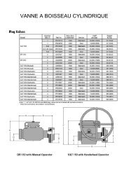
INTERCONNECTING COMPONENTS<br />
RAILCAR COUPLINGS<br />
The Railcar Coupling is an integral crossover (adaptor) to<br />
be mounted onto railcars (and trucks) in order to allow<br />
fast & safe connection to loading arms. The product is fully<br />
certified and CE marked in conformity with PED 97/23/EC for<br />
use in the EEC.<br />
Application:<br />
Loading and unloading of various liquid and gaseous<br />
fluids (hydrocarbons, refined, chemicals, LPG, NH3, etc.).<br />
Suitable to low temperature - 46°C.<br />
Size & Rating:<br />
Wing union size…....... : 2” and 3” figure 602 (Acme thread).<br />
Flange size.................. : 2” (DN50) and 3” (DN80).<br />
Flange rating............... : ISO PN40 raised face (Schedule 40).<br />
Pressure rating............ : 20 bars.<br />
Temperature rating.... : -46°C to 80°C.<br />
Material:<br />
Carbon steel A350 LF2.<br />
38<br />
The connection is a wing union Fig. 602<br />
1 - The spherically profiled male plug provides a metal-tometal<br />
secondary seal.<br />
2 - Acme or ISO union thread.<br />
3 - Forged wing union nut.<br />
4 - The primary seal element can be supplied in different<br />
material to suit fluid service (Buna, Viton, etc.).<br />
5 - A chain retains the nut whilst the coupling is connected with<br />
the loading arm.<br />
6 - Raised face flange (Sch. 40).<br />
Options:<br />
- 1/4” sampling point with isolating valve.<br />
- Perforated nut for closure with standard pin-wrench<br />
instead of hammer.<br />
- Wing union with ISO thread.<br />
- Locator hole on flange (for eccentric coupling).<br />
- Welded construction or special fabrication.<br />
SAFETY ALERT<br />
Always use a bronze hammer in order to avoid sparkling whilst<br />
striking onto the wing union nut, in particular when operating<br />
in a hazardous area.<br />
Always use an original <strong>FCE</strong> wing union. The use of an inferior<br />
copy may seriously affect the safety level required.<br />
INSPECTION KIT<br />
An identification and wear detection gauge kit for railcar wing<br />
unions is available complete with its own transport case.
INTERCONNECTING COMPONENTS<br />
RAILCAR COUPLINGS<br />
Concentric Railcar Coupling<br />
Dim. in mm 2" union x DN50 3" union x DN80<br />
A 200 240<br />
B 52 78<br />
C 125 160<br />
D 165 200<br />
E 175 185<br />
F 4 8<br />
G 18 18<br />
Weight in kg 9.2 14.8<br />
F = number of holes<br />
G = diameter of hole<br />
Eccentric Railcar Coupling (for gas phase)<br />
Dim. in mm 2" union x DN80<br />
A 185<br />
B 78<br />
C 120<br />
D 200<br />
Weight in kg 11.6<br />
39<br />
INTERCONNECTING COMPONENTS<br />
LPG REGO UNIONS & ADAPTORS<br />
General application:<br />
Generally used for cold temperature and gaseous fluids,<br />
the REGO union provides a safe, quick and efficient<br />
connection onto LPG trucks for domestic supply (butane /<br />
propane) and also onto loading arms or any rotating<br />
piping systems.<br />
Assembly description:<br />
The REGO union is similar to a wing union but the nut is<br />
attached to the female sub.<br />
The nut is grooved for wrench tightening by a ”Tricoise”<br />
wrench. 1” 3/4 and 3” 1/4 ACME Union threads are available.<br />
Union subs are available for several piping assemblies:<br />
NPT or BSP thread or Buttweld (sch.40).<br />
Size & Rating:<br />
Nominal sizes............. : 1” and 2”.<br />
Pressure rating........... : Up to 50 bar (725 psi).<br />
Temperature rating... : - 46°C to 80°C.<br />
Material:<br />
Carbon steel A350 LF2 (other on request).<br />
O-ring seal:<br />
The O-ring seal provides many advantages:<br />
- Better sealing than a flat gasket.<br />
- No seal loss whilst disconnecting.<br />
Seal material: Buna (other material on request).<br />
Adaptors:<br />
Adaptors between REGO union and other connections are<br />
available as follow:<br />
REGO x wing union.<br />
REGO x flange (ANSI, DIN, ISO).<br />
REGO x reduced REGO.<br />
REGO x Flange adaptor<br />
Reference Flange rating L in mm<br />
REG2 - 25 2" PN 25 110<br />
REG2 - 50 2" PN 50 115<br />
REG3 - 25 3" PN 25 120<br />
REG3 - 50 3" PN 50 135<br />
REGO 3" ¼ ACME F x 1" ¾ ACME M<br />
L in mm 65
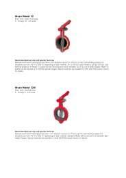
SPECIAL FABRICATION<br />
BUTTERFLY VALVES<br />
In particular cases, the original valves may not match<br />
specific client requirements for low temperature service or<br />
chemical compatibility with the fluid (H2S, etc.).<br />
<strong>FCE</strong> manufactures special butterfly valve bodies specifically<br />
engineered and using materials selected for compatibility<br />
to your application or specific requirement (PED, etc).<br />
VALVE ACCESSORIES<br />
<strong>FCE</strong> offers useful accessories such as:<br />
- Stem extension:<br />
Can be equipped with a manual handle or a gear actuator.<br />
40<br />
- ”ARO” Position Indicator:<br />
Can be supplied with an extended handle for valves from<br />
2” to 6”.<br />
The position indicator is fitted with a light refractant arrow.<br />
SPECIAL FABRICATION<br />
VALVE ACTUATORS<br />
For specific applications, manually operated valves may require actuators not available from the original<br />
manufacturer. <strong>FCE</strong> provides, on a case by case basis, engineering, assembly and testing for specific interfaces<br />
between valves or chokes and operators, which can be pneumatic, hydraulic or electrically powered.<br />
Examples:<br />
Hydraulic operator onto a plug valve<br />
Pneumatic actuator onto an adjustable choke
SPECIAL FABRICATION<br />
CASING SWAGES<br />
Casing size Cold Working<br />
Short casing thread<br />
Buttress casing thread<br />
OD in in. Pressure PSI Height in in. Weight in lbs Height in in. Weight in lbs<br />
4" ½ 10000 7.75 28 8.75 31<br />
5" ½ 10000 7.75 29 8.75 32<br />
7" 10000 6.88 31 8 34<br />
7" 5 ⁄8 10000 7 34 8.12 38<br />
8" 5 ⁄8 10000 5.87 44 7 48<br />
9" 5 ⁄8 10000 5.96 57 7.09 62<br />
10" ¾ 5000 5.93 59 6.94 64<br />
11" ¾ 5000 6 72 7.01 77<br />
13" 3 ⁄8 5000 6.1 99 7.11 106<br />
16" 1500 6.32 104 6.93 108<br />
18" 5 ⁄8 1500 6.14 147 7.03 154<br />
20" 1500 6.47 175 7.08 180<br />
Casing swage<br />
General application:<br />
A circulating swage is an adapter that enables a temporary circulating line<br />
to be rigged to the top of the casing string, allowing circulation of fluids<br />
during casing installation. It is generally required as a contingency option<br />
to enable any obstruction or fill to be circulated clear during the running<br />
process.<br />
Union plug<br />
onto casing<br />
swage<br />
41<br />
Lifting Device<br />
SPECIAL FABRICATION<br />
API BLOCKS & SPOOLS<br />
Forged blocks, elbows, spools, tees and spacers are supplied<br />
to API-6A standard dimensions.<br />
Standard design data:<br />
API 6A and NACE MR01-75 for sour gas service.<br />
Nominal line size.................. : 2” up to 7”.<br />
Standard rating................... : 5000/10000/15000 PSI.<br />
Temperature rating............. : to customer request.<br />
Inspection level per API...... : to customer request.<br />
Material class....................... : to customer request.<br />
Options:<br />
- Special dimensions<br />
(rectangular blocks, buffer chambers).<br />
- Instrument ports (No. & size to required specification).<br />
- Fixation tapped holes.<br />
- API Monogram, if required.
+33 (0)4 77 48 13 13<br />
+33 (0)4 77 33 01 30<br />
fce@fce.fr<br />
786 rue George Sand - ZI Molina la Chazotte<br />
42350 La Talaudière FRANCE<br />
Fluid Control Algérie<br />
Zone d’Activité N°3 Lot 17<br />
BP 506<br />
30500 Hassi Messaoud<br />
Algérie<br />
+213 (0)29 73 73 35<br />
fca@fce.fr<br />
Création graphique : District 360 - Impression i.d.0 - 04 77 52 96 09<br />
certifié imprim’vert, imprimé sur papier couché moderne 300g recyclable<br />
Label PEFC (certification de gestion forestière durable) - 02/2010