Circularly Polarized Microstrip Patch Antenna with T-Shaped ... - iject
Circularly Polarized Microstrip Patch Antenna with T-Shaped ... - iject
Circularly Polarized Microstrip Patch Antenna with T-Shaped ... - iject

You also want an ePaper? Increase the reach of your titles
YUMPU automatically turns print PDFs into web optimized ePapers that Google loves.
IJECT Vo l . 4, Is s u e Sp l - 4, Ap r i l - Ju n e 2013<br />
ISSN : 2230-7109 (Online) | ISSN : 2230-9543 (Print)<br />
<strong>Circularly</strong> <strong>Polarized</strong> <strong>Microstrip</strong> <strong>Patch</strong> <strong>Antenna</strong><br />
<strong>with</strong> T-<strong>Shaped</strong> Slot<br />
1 Sanyog Rawat, 2 K K Sharma<br />
1<br />
Amity School of Engineering and Technology, Amity University Rajasthan, India<br />
2<br />
Malaviya National Institute of Technology, Jaipur, Rajasthan, India<br />
Abstract<br />
In this paper a new geometry of circularly polarized patch antenna<br />
is proposed <strong>with</strong> improved bandwidth. The radiation performance<br />
of proposed patch antenna is investigated using IE3D simulation<br />
software and its performance is compared <strong>with</strong> that of conventional<br />
circular patch antenna. The simulated return loss, axial ratio and<br />
impedance <strong>with</strong> frequency for the proposed antenna are reported<br />
in this paper. It is shown that by selecting suitable slot dimension,<br />
air gap and location of the slots, the impedance bandwidth can<br />
be enhanced upto 10.74% as compared to conventional circular<br />
patch (3.41%) <strong>with</strong> an axial ratio bandwidth of 2.46%.<br />
mm is also added between patch and ground plane, as shown<br />
in fig. 2(a) and (b). Here conventional circular patch antenna<br />
is considered the reference antenna to compare the results of<br />
proposed geometry.<br />
Keywords<br />
<strong>Microstrip</strong> <strong>Patch</strong>, Circular Polarization, Bandwidth, Axial-Ratio,<br />
Circular <strong>Patch</strong><br />
I. Introduction<br />
The antenna manufacturing industry has experienced a significant<br />
growth in the past several years. There is an essential need for a light<br />
weight and good performance antenna for modern communication<br />
applications. In order to meet these demands, microstrip patch<br />
antenna is one of the potential candidate for it. They are suitable<br />
for many applications like mobiles, aircraft, satellite, missile etc.<br />
They are low profile structure, robust in nature, inexpensive to<br />
manufacture, compatible <strong>with</strong> MMIC designs and relatively light<br />
and compact [1]. A microstrip antenna consists of conducting<br />
patch on a ground plane separated by dielectric substrate. The<br />
conducting patch can take any shape like rectangular, elliptical,<br />
square, circular, triangle etc. but rectangular and circular<br />
configurations are the most commonly used geometries [2].<br />
Other configurations are complex to analyze and require heavy<br />
numerical computations. Among the conventional microstrip<br />
antenna geometries, circular microstrip antenna is widely analyzed<br />
antenna due to easy modelling and applicable boundary conditions<br />
[3]. The major drawback of circular microstrip patch antenna is<br />
narrow bandwidth and low gain especially at lower microwave<br />
frequencies [4]. With the insertion of slots in the patch-geometry,<br />
the path of the patch current increases which in turn increases the<br />
impedance bandwidth of an antenna. The skimmer shaped circular<br />
microstrip patch antenna to increase bandwidth up to 4.13% have<br />
been investigated [5] and bandwidth improvement by 2.3 times of<br />
the conventional antenna bandwidth (1.4%) using slots in circular<br />
microstrip patch antenna is also investigated in past [6].<br />
There is another easy way to improve the performance of patch<br />
antennas by introducing air gap between the radiating patch and the<br />
ground plane. Thus, higher bandwidth can be achieved [7]. Circular<br />
polarization is an additional requirement in communication and<br />
it may be achieved either through selection of proper feed<br />
location [8], insertion of suitable slot [9] or through stacking of<br />
patch elements [10].<br />
II. <strong>Antenna</strong> Geometry<br />
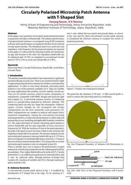
A conventional circular patch shown in fig. 1 is modified by<br />
introduction of T shaped slot at the edge. An air stacking of 1<br />
Figure1. Circular microstrip patch antenna<br />
The patch has the diameter of 20 mm. A 50Ω coaxial probe is<br />
used to connect the microstrip patch at coordinates.<br />
Fig. 2(a): Proposed Geometry of <strong>Antenna</strong> (All Dimensions in<br />
mm)<br />
Fig. 2(b): Side View of the Proposed Geometry <strong>with</strong> Coaxial<br />
Feed<br />
www.<strong>iject</strong>.org International Journal of Electronics & Communication Technology 65
IJECT Vo l . 4, Is s u e Sp l - 4, Ap r i l - Ju n e 2013 ISSN : 2230-7109 (Online) | ISSN : 2230-9543 (Print)<br />
The dimensions of T-slot are: vertical arm’s length of 3mm and<br />
vertical arm’s width, horizontal arm’s length & width each of 1mm.<br />
The position of T-slot is (6.5, 0). Thus, impedance-bandwidth of<br />
10.74% can be obtained from the above geometry.<br />
The proposed geometry is designed on glass epoxy FR4 substrate<br />
having thickness h =1.59mm, substrate dielectric constant =4.4,<br />
substrate loss tangent tan δ= 0.024 and relative permeability<br />
=1 <strong>with</strong> an air-gap of 1 mm(foam is used for air-gap). The wider<br />
bandwidth and higher gain (due to air-gap) than the conventional<br />
circular patch <strong>with</strong> simple topology and improvement in the other<br />
antenna radiation parameters are the main advantages of this<br />
geometry. Many simulations are done for optimizing the length;<br />
width and location of the slot and best results are obtained <strong>with</strong><br />
defined length and width of the T-slot. Due to existence of the<br />
T-slot, the current distribution changes and another mode is excited.<br />
Each mode has its own cut-off frequency and thus the proposed<br />
geometry has a new resonant frequency, which is different from<br />
conventional patch resonant frequency.<br />
III. Simulation Results<br />
The simulation results of conventional rectangular patch and<br />
proposed geometry are obtained using IE3D Software [11].<br />
A. Radiation Pattern<br />
A plot through which it is visualized where the antenna transmits<br />
or receives power. The microstrip antenna radiates normal to its<br />
patch surface. So, the elevation pattern for φ= 0 0 and φ= 90 0 are<br />
important for the simulation.<br />
Fig. 4: Computed Elevation Pattern for the Proposed Geometry<br />
The simulated E-plane patterns i.e. the two dimensional patternview<br />
of the geometries is illustrated in fig. 3 and 4. Radiation<br />
patterns are found to be smooth and uniform over the band of<br />
frequencies for both the geometries.<br />
B. Return Loss and Bandwidth<br />
Return Loss is a measure of how much power is delivered from<br />
the source to a load and is measured by S 11<br />
parameters. The range<br />
of frequencies over which the antenna can operate effectively is<br />
characterized by bandwidth. It can be calculated by going 10dB<br />
down in return loss.<br />
Fig. 3: Computed Elevation Pattern for the Conventional<br />
Geometry<br />
Fig. 5: Computed Variation of Return Loss With Frequency for<br />
Conventional Geometry<br />
66 International Journal of Electronics & Communication Technology<br />
www.<strong>iject</strong>.org
ISSN : 2230-7109 (Online) | ISSN : 2230-9543 (Print)<br />
IJECT Vo l . 4, Is s u e Sp l - 4, Ap r i l - Ju n e 2013<br />
Fig. 6: Computed Variation of Return Loss With Frequency for<br />
Proposed Geometry<br />
The variation of return loss <strong>with</strong> frequency is shown in fig. 5 and<br />
6. The conventional patch antenna resonates at frequency of 3.96<br />
GHz <strong>with</strong> -63.53dB return loss and the impedance bandwidth<br />
obtained is 3.41%. The proposed patch antenna has -32.23dB<br />
return loss at resonating frequency of 4.96 GHz and the impedance<br />
bandwidth obtained is 10.74%.<br />
C. Smith Chart<br />
Smith Chart provides the information about the polarization and<br />
the impedance-matching of the radiating patch.<br />
Fig. 8: Variation of Input Impedance With Frequency for Proposed<br />
Geometry<br />
Simulated input impedance variation <strong>with</strong> frequency is shown<br />
in fig. 7 and 8. The circle passes through the centre of the smith<br />
chart represents the impedance match of (49.93-j0.004)Ω for<br />
conventional patch and (51.52+j1.97)Ω for proposed geometry<br />
<strong>with</strong> the coaxial probe and it shows that both geometries have<br />
good impedance matching.<br />
D. Gain<br />
Gain is basically the measure of effectiveness of a directional<br />
antenna as compared to that of a standard non-directional<br />
antenna.<br />
Fig. 7: Variation of Input Impedance With Frequency for<br />
Conventional Geometry<br />
Fig. 9: Computed Variation of Gain With Frequency for<br />
Conventional Geometry<br />
www.<strong>iject</strong>.org International Journal of Electronics & Communication Technology 67
IJECT Vo l . 4, Is s u e Sp l - 4, Ap r i l - Ju n e 2013 ISSN : 2230-7109 (Online) | ISSN : 2230-9543 (Print)<br />
Fig. 10: Computed Variation of Gain With Frequency for Proposed<br />
Geometry<br />
The variation of gain <strong>with</strong> frequency for the conventional and<br />
proposed geometry is shown in fig. 9 and 10. The gain for<br />
conventional geometry is 2.65 dBi and for proposed geometry is<br />
6.12 dBi at resonant frequency; it shows that proposed geometry<br />
has much higher gain over the entire band of frequencies than<br />
conventional geometry.<br />
E. Axial Ratio<br />
This is related <strong>with</strong> quality of circular polarization of an antenna<br />
and axial ratio bandwidth is obtained by calculating the range of<br />
frequencies falling between 0 dB to 3 dB.<br />
Fig. 12: Variation of Axial Ratio With Frequency for Proposed<br />
Geometry<br />
The variation of axial ratio <strong>with</strong> frequency for conventional<br />
patch antenna is shown in fig. 11 it is observed that conventional<br />
geometry is not circularly polarized <strong>with</strong> axial ratio of 51.84dB<br />
at resonant frequency. The axial ratio observed for the proposed<br />
geometry is shown in fig. 12, the geometry is found to be circularly<br />
polarized <strong>with</strong> axial ratio of 0.83dB at resonant frequency and<br />
axial ratio bandwidth of 2.46%.<br />
The comparison between radiation parameters of conventional<br />
patch antenna and proposed geometry is tabulated in Table 1.<br />
Table 1: Comparison of Conventional and Proposed Geometry<br />
Sr.<br />
No.<br />
1.<br />
2.<br />
3.<br />
Parameters<br />
Resonant<br />
Frequency<br />
(GHz)<br />
Return loss<br />
(dB)<br />
Bandwidth<br />
(%)<br />
Conventional<br />
<strong>Patch</strong><br />
3.96 4.96<br />
-63.53 -32.23<br />
3.41 10.74<br />
Proposed <strong>Patch</strong><br />
4. Gain(dBi) 2.65 6.12<br />
4.<br />
Axial Ratio<br />
(dB)<br />
51.84<br />
0.83<br />
(2.46%)<br />
Fig. 11: Variation of Axial Ratio With Frequency for Conventional<br />
Geometry<br />
IV. Conclusion<br />
This paper presents the radiation performance of proposed patch<br />
antenna. The performance of proposed geometry has been compared<br />
<strong>with</strong> conventional geometry. Simulated results indicate that the<br />
antenna exhibits axial ratio bandwidth upto 2.46% by optimizing<br />
the length, width of slots and air gap in proposed antenna geometry.<br />
There is also improvement in impedance bandwidth upto 10.70%.<br />
The radiation patterns in entire bandwidth are identical in nature,<br />
and the direction of maximum radiations over the whole bandwidth<br />
is directed normal to the patch geometry. The obtained results<br />
suggest that proposed antenna may be considered as suitable<br />
candidate for modern wireless communication.<br />
68 International Journal of Electronics & Communication Technology<br />
www.<strong>iject</strong>.org
ISSN : 2230-7109 (Online) | ISSN : 2230-9543 (Print)<br />
IJECT Vo l . 4, Is s u e Sp l - 4, Ap r i l - Ju n e 2013<br />
V. Acknowledgment<br />
The authors would like to thank the authorities of Amity University<br />
Rajasthan and Malaviya National Institute of Technology, Jaipur<br />
for providing the necessary facilities and support.<br />
References<br />
[1] R. Garg, P. Bhartia, I. J. Bhal, A. Ittipiboon,“<strong>Microstrip</strong><br />
<strong>Antenna</strong> Design Book”, Artech House, New York, 2001.<br />
[2] G. Kumar, K.P. Ray,“Broadband <strong>Microstrip</strong> <strong>Antenna</strong>s”,<br />
Artech House, Boston, 2003.<br />
[3] Koray Surmeli, Bahattin Turetken,“U-Slot Stacked <strong>Patch</strong><br />
<strong>Antenna</strong> using High and Low Dielectric Constant Material<br />
Combination in S-Band”, General Assembly and Scientific<br />
Symposium, URSI, August 2011.<br />
[4] Jagtar Singh, A.P Singh, T.S.Kamal,“Design of Circular<br />
<strong>Microstrip</strong> <strong>Antenna</strong> using Artificial Neural Networks”,<br />
Proceedings of the World Congress on Engineering, Vol.<br />
11, U.K, 2011.<br />
[5] Mi-Ra Ryu, Jong-Myung Woo, J. Hu,“Skimmer shaped<br />
Linear <strong>Polarized</strong> <strong>Microstrip</strong> <strong>Antenna</strong>s for Miniaturization”,<br />
International Conference on Advance Communication<br />
Technology, Vol. 1, 4, pp. 758, 2006.<br />
[6] Wu, Jeun Wen, Jui Han Lu,“Slotted Circular <strong>Microstrip</strong> <strong>Patch</strong><br />
<strong>Antenna</strong> for Bandwidth Enhancement”, IEEE Proceeding<br />
Microwave <strong>Antenna</strong>s Propagation, Vol. 2, pp. 272-275,<br />
2003.<br />
[7] Dheeraj Bhardwaj, Komal Sharma, D. Bhatnagar, S.<br />
Sancheti,“Broad Band Parasitically Coupled Concentric Semi<br />
Circular Elliptically Ring <strong>Antenna</strong> Surrounding an Elliptical<br />
<strong>Patch</strong> <strong>with</strong> Air Gap”, 2009 IEEE Applied Electromagnetics<br />
Conference-AEMC, pp. 1-4, 2009.<br />
[8] K.P. Ray, D.D. Krishna,“Compact Dual Band Suspended<br />
Semi-Circular <strong>Microstrip</strong> <strong>Antenna</strong> <strong>with</strong> Half U-slot”,<br />
Microwave Optical Technology Letter No. 48, pp. 2021-<br />
2024, 2007.<br />
[9] Garima, D. Bhatnagar, J.S. Saini, V.K. Saxena, L.M. Joshi,<br />
“Design of Broadband Circular <strong>Antenna</strong> <strong>with</strong> Diamond<br />
Shape Slot”, Indian Journal of Radio & Science Physics,<br />
Vol. 40, pp. 275-281, October 2011.<br />
[10] S. Shekhawat, P. Sekra, D. Bhatnagar, V.K Saxena, J.S Saini,<br />
“Stacked Arrangement of Rectangular <strong>Microstrip</strong> <strong>Patch</strong>es<br />
for <strong>Circularly</strong> <strong>Polarized</strong> Broadband Performance”, IEEE<br />
<strong>Antenna</strong>s Wireless Propagation Letter No. 9, pp. 910–913,<br />
2010.<br />
[11] IE3D software, Release 14.65(Zeland Software Inc.,<br />
Freemont, USA), April 2010.<br />
www.<strong>iject</strong>.org International Journal of Electronics & Communication Technology 69