COVER - Encompass Imaging
COVER - Encompass Imaging COVER - Encompass Imaging
3. SELF-DIAGNOSIS CODE TABLE Repaired by: C C C C C C C C C C C C C C C C C C C C C C C E E E E Self-diagnosis Code Block Function 0 4 2 1 2 2 3 1 3 1 3 1 3 1 3 1 3 1 3 1 3 1 3 1 3 1 3 1 3 1 3 2 3 2 3 2 3 2 3 2 3 2 3 2 3 2 6 1 6 1 6 2 6 2 Detailed Code 0 0 0 0 0 0 1 0 1 1 2 0 2 1 2 2 2 3 2 4 3 0 4 0 4 2 1 0 1 1 2 0 2 1 2 2 2 3 2 4 3 0 4 0 4 2 0 0 1 0 0 0 0 1 Symptom/State Non-standard battery is used. Condensation. Video head is dirty. LOAD direction. Loading does not complete within specified time UNLOAD direction. Loading does not complete within specified time T reel side tape slacking when unloading. Winding S reel fault when counting the rest of tape. T reel fault. S reel fault. T reel fault. FG fault when starting capstan. FG fault when starting drum. FG fault during normal drum operations. LOAD direction loading motor timeout. UNLOAD direction loading motor time-out. T reel side tape slacking when unloading. Winding S reel fault when counting the rest of tape. T reel fault. S reel fault. T reel fault. FG fault when starting capstan. FG fault when starting drum FG fault during normal drum operations Difficult to adjust focus (Cannot initialize focus.) Zoom operations fault (Cannot initialize zoom lens.) Steadyshot function does not work well. (With pitch angular velocity sensor output stopped.) Steadyshot function does not work well. (With yaw angular velocity sensor output stopped.) 1-3E DCR-TRV12E/TRV14E/TRV19/TRV19E Correction Use the info LITHIUM battery. Remove the cassette, and insert it again after one hour. Clean with the optional cleaning cassette. Load the tape again, and perform operations from the beginning. Load the tape again, and perform operations from the beginning. Load the tape again, and perform operations from the beginning. Load the tape again, and perform operations from the beginning. Load the tape again, and perform operations from the beginning. Load the tape again, and perform operations from the beginning. Load the tape again, and perform operations from the beginning. Load the tape again, and perform operations from the beginning. Load the tape again, and perform operations from the beginning. Load the tape again, and perform operations from the beginning. Remove the battery or power cable, connect, and perform operations from the beginning. Remove the battery or power cable, connect, and perform operations from the beginning. Remove the battery or power cable, connect, and perform operations from the beginning. Remove the battery or power cable, connect, and perform operations from the beginning. Remove the battery or power cable, connect, and perform operations from the beginning. Remove the battery or power cable, connect, and perform operations from the beginning. Remove the battery or power cable, connect, and perform operations from the beginning. Remove the battery or power cable, connect, and perform operations from the beginning. Remove the battery or power cable, connect, and perform operations from the beginning. Remove the battery or power cable, connect, and perform operations from the beginning. Inspect the lens block focus reset sensor (Pin 7 of CN1201 of VC- 311 board) when focusing is performed when the focus buttons of the touch panel are pressed in the focus manual mode, and the focus motor drive circuit (IC1201 of VC-311 board) when the focusing is not performed. Inspect the lens block zoom reset sensor (Pin qh of CN1201 of VC-311 board) when zooming is performed when the zoom lens is operated and the zoom motor drive circuit (IC1201 of VC-311 board) when zooming is not performed. Inspect pitch angular velocity sensor (SE5402 of MA-421 board) peripheral circuits. Inspect yaw angular velocity sensor (SE5401 of MA-421 board) peripheral circuits.
COVER SECTION 2 DISASSEMBLY HELP The following flow chart shows the disassembly procedure. DISASSEMBLY HELP DISASSEMBLY DISASSEMBLY PROCEDURE OF REMOVING MECHANISM DECK 1 2-2. CABINET (R) COVER (39E) ASSEMBLY ........ (page 2-4) 2 2-3. F PANEL SECTION ........................................ (page 2-5) 3 2-5. CABINET (R) SECTION ................................... (page 2-7) 4 2-10. BT PANEL/EVF SECTION ........................... (page 2-11) 5 2-14. VA-118 BOARD, LENS SECTION ................ (page 2-15) 6 2-16. MECHANISM DECK, VC-311 BOARD (1) .... (page 2-16) 7 2-17. MECHANISM DECK, VC-311 BOARD (2) .... (page 2-17) SERVICE POSITION TO CHECK THE VTR SECTION 2-1 DISASSEMBLY DISASSEMBLY HELP DISASSEMBLY DCR-TRV12E/TRV14E/TRV19/TRV19E DISASSEMBLY HELP PD-188 board service position DISASSEMBLY HELP DISASSEMBLY HELP
- Page 1 and 2: SERVICE MANUAL Ver 1.0 2003. 02 Rev
- Page 3 and 4: • SUPPLIED ACCESSORIES Make sure
- Page 5 and 6: 5-2. ELECTRICAL PARTS LIST ····
- Page 7: DCR-TRV12E/TRV14E/TRV19/TRV19E 1-2.
- Page 11 and 12: 2-1. P CABINET (C) ASSEMBLY Caution
- Page 13 and 14: 2-3. F PANEL SECTION 3 Open the Cas
- Page 15 and 16: 2-5. CABINET (R) SECTION 4 Three sc
- Page 17 and 18: 2-8. PD-188 BOARD, LCD UNIT 3 Four
- Page 19 and 20: 2-10. BT PANEL/EVF SECTION 1 Screw
- Page 21 and 22: 2-12. LB-085 BOARD (REMOVING OF THE
- Page 23 and 24: 2-14. VA-118 BOARD, LENS SECTION 8
- Page 25 and 26: 2-17. MECHANISM DECK, VC-311 BOARD
- Page 27 and 28: F panel section 40 21 41 20 IC4101
- Page 29 and 30: 2-21E DCR-TRV12E/TRV14E/TRV19/TRV19
- Page 31 and 32: DCR-TRV12E/TRV14E/TRV19/TRV19E OVER
- Page 33 and 34: COVER Link 3. BLOCK DIAGRAMS DCR-TR
- Page 35 and 36: DCR-TRV12E/TRV14E/TRV19/TRV19E COVE
- Page 37 and 38: DCR-TRV12E/TRV14E/TRV19/TRV19E COVE
- Page 39 and 40: DCR-TRV12E/TRV14E/TRV19/TRV19E COVE
- Page 41 and 42: DCR-TRV12E/TRV14E/TRV19/TRV19E COVE
- Page 43 and 44: COVER Link CD-430 BOARD (CCD IMAGER
- Page 45 and 46: COVER 4-2. SCHEMATIC DIAGRAMS A B C
- Page 47 and 48: COVER For Schematic Diagram • Ref
- Page 49 and 50: DCR-TRV12E/TRV14E/TRV19/TRV19E COVE
- Page 51 and 52: COVER For Schematic Diagram • Ref
- Page 53 and 54: COVER For Schematic Diagram • Ref
- Page 55 and 56: A B C D COVER 4-2. SCHEMATIC DIAGRA
- Page 57 and 58: COVER For Schematic Diagram • Ref
<strong>COVER</strong> SECTION 2<br />
DISASSEMBLY<br />
HELP<br />
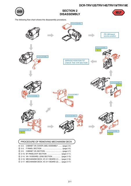
The following flow chart shows the disassembly procedure.<br />
DISASSEMBLY<br />
HELP<br />
DISASSEMBLY<br />
DISASSEMBLY<br />
PROCEDURE OF REMOVING MECHANISM DECK<br />
1 2-2. CABINET (R) <strong>COVER</strong> (39E) ASSEMBLY ........ (page 2-4)<br />
2 2-3. F PANEL SECTION ........................................ (page 2-5)<br />
3 2-5. CABINET (R) SECTION ................................... (page 2-7)<br />
4 2-10. BT PANEL/EVF SECTION ........................... (page 2-11)<br />
5 2-14. VA-118 BOARD, LENS SECTION ................ (page 2-15)<br />
6 2-16. MECHANISM DECK, VC-311 BOARD (1) .... (page 2-16)<br />
7 2-17. MECHANISM DECK, VC-311 BOARD (2) .... (page 2-17)<br />
SERVICE POSITION TO<br />
CHECK THE VTR SECTION<br />
2-1<br />
DISASSEMBLY<br />
DISASSEMBLY<br />
HELP<br />
DISASSEMBLY<br />
DCR-TRV12E/TRV14E/TRV19/TRV19E<br />
DISASSEMBLY<br />
HELP<br />
PD-188 board<br />
service position<br />
DISASSEMBLY<br />
HELP<br />
DISASSEMBLY<br />
HELP


