COVER - Encompass Imaging
COVER - Encompass Imaging COVER - Encompass Imaging
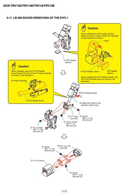
DCR-TRV12E/TRV14E/TRV19/TRV19E 2-11. LB-085 BOARD (REMOVING OF THE EVF)-1 Caution When installing, pass the FP-619 flexible board through the hole of the VF hinge assembly as shown in the illustration. VF hinge assembly FP-619 flexible board 3 Two screws (M1.7 × 2.5), lock ace, p2 7 VF tilt cabinet 9 Screw (M1.7 × 2.5), lock ace, p2 1 EVF flexible retainer 5 Three screws (M1.7 × 4), lock ace, p2 q; Eye cup (40) assembly 2-12 6 VF hinge assembly 8 Screw (M1.7 × 2.5), lock ace, p2 Caution When installing the EVF flexible retainer, please be sure to install it while the viewfinder is kept pushed up to attach. FP-619 flexible board FP-619 flexible board 2 Raise the Finder in the direction of the arrow 4 Screw (M1.7 × 2.5), lock ace, p2 Finder EVF flexible retainer When installing the EVF flexible retainer, fold the FP-619 flexible board as shown in the illustration.
2-12. LB-085 BOARD (REMOVING OF THE EVF)-2 To raise the VF slide cabinet (upper) assembly, insert a flat head (-) screwdriver into the position shown by the arrow. VF slide cabinet (upper) assembly VF slide cabinet (lower) A 2 3 Two claws RE-ASSEMBLING THE VF SLIDE CABINET 1 VF slide assembly When re-assembling is completed, the VF slide cabinet (upper) assembly and the VF slide cabinet (lower) are assembled as shown. VF slide cabinet (upper) assembly VF slide cabinet (lower) Visiblity knob (40) 5 4 B 6 C 2 A 2-13 DCR-TRV12E/TRV14E/TRV19/TRV19E VF slide cabinet (upper) assembly 1 Tapping screw (M1.7 × 3.5) 2 Open the lock of the VF slide cabinet (lower) in the direction of the arrow A, 3 release the two claws of the VF slide cabinet (upper) assembly, 4 while slanting the VF slide cabinet (upper) in the direction of the arrow B, 5 remove the Visibility knob (40) from the VF slide cabinet (lower), and 6 remove the VF slide cabinet (upper) assembly by sliding it in the direction of the arrow C. VF slide cabinet (lower) Visiblity knob (40) Two claws 2 Align the dotted portion of the VF slide assembly with the dotted line of the VF slide cabinet (lower). VF slide cabinet (lower) VF slide cabinet (lower) When re-assembling, slide the Visibility knob (40) to the fully right-end beforehand. 3 Slide the VF slide cabinet assembly up to the position in the direction of the arrow where the two claws are locked. 4 Tapping screw (M1.7 × 3.5)
- Page 1 and 2: SERVICE MANUAL Ver 1.0 2003. 02 Rev
- Page 3 and 4: • SUPPLIED ACCESSORIES Make sure
- Page 5 and 6: 5-2. ELECTRICAL PARTS LIST ····
- Page 7 and 8: DCR-TRV12E/TRV14E/TRV19/TRV19E 1-2.
- Page 9 and 10: COVER SECTION 2 DISASSEMBLY HELP Th
- Page 11 and 12: 2-1. P CABINET (C) ASSEMBLY Caution
- Page 13 and 14: 2-3. F PANEL SECTION 3 Open the Cas
- Page 15 and 16: 2-5. CABINET (R) SECTION 4 Three sc
- Page 17 and 18: 2-8. PD-188 BOARD, LCD UNIT 3 Four
- Page 19: 2-10. BT PANEL/EVF SECTION 1 Screw
- Page 23 and 24: 2-14. VA-118 BOARD, LENS SECTION 8
- Page 25 and 26: 2-17. MECHANISM DECK, VC-311 BOARD
- Page 27 and 28: F panel section 40 21 41 20 IC4101
- Page 29 and 30: 2-21E DCR-TRV12E/TRV14E/TRV19/TRV19
- Page 31 and 32: DCR-TRV12E/TRV14E/TRV19/TRV19E OVER
- Page 33 and 34: COVER Link 3. BLOCK DIAGRAMS DCR-TR
- Page 35 and 36: DCR-TRV12E/TRV14E/TRV19/TRV19E COVE
- Page 37 and 38: DCR-TRV12E/TRV14E/TRV19/TRV19E COVE
- Page 39 and 40: DCR-TRV12E/TRV14E/TRV19/TRV19E COVE
- Page 41 and 42: DCR-TRV12E/TRV14E/TRV19/TRV19E COVE
- Page 43 and 44: COVER Link CD-430 BOARD (CCD IMAGER
- Page 45 and 46: COVER 4-2. SCHEMATIC DIAGRAMS A B C
- Page 47 and 48: COVER For Schematic Diagram • Ref
- Page 49 and 50: DCR-TRV12E/TRV14E/TRV19/TRV19E COVE
- Page 51 and 52: COVER For Schematic Diagram • Ref
- Page 53 and 54: COVER For Schematic Diagram • Ref
- Page 55 and 56: A B C D COVER 4-2. SCHEMATIC DIAGRA
- Page 57 and 58: COVER For Schematic Diagram • Ref
- Page 59 and 60: COVER Link DCR-TRV12E/TRV14E/TRV19/
- Page 61 and 62: COVER 4-2. SCHEMATIC DIAGRAMS 4-3.
- Page 63 and 64: COVER 4-2. SCHEMATIC DIAGRAMS 4-3.
- Page 65 and 66: COVER 4-2. SCHEMATIC DIAGRAMS 4-3.
- Page 67 and 68: COVER 4-2. SCHEMATIC DIAGRAMS 4-3.
- Page 69 and 70: COVER 4-2. SCHEMATIC DIAGRAMS 4-3.
DCR-TRV12E/TRV14E/TRV19/TRV19E<br />
2-11. LB-085 BOARD (REMOVING OF THE EVF)-1<br />
Caution<br />
When installing, pass the FP-619 flexible<br />
board through the hole of the VF hinge assembly<br />
as shown in the illustration.<br />
VF hinge assembly<br />
FP-619 flexible board<br />
3 Two screws<br />
(M1.7 × 2.5),<br />
lock ace, p2<br />
7 VF tilt cabinet<br />
9 Screw<br />
(M1.7 × 2.5),<br />
lock ace, p2<br />
1 EVF flexible<br />
retainer<br />
5 Three screws<br />
(M1.7 × 4),<br />
lock ace, p2<br />
q; Eye cup (40)<br />
assembly<br />
2-12<br />
6 VF hinge<br />
assembly<br />
8 Screw<br />
(M1.7 × 2.5),<br />
lock ace, p2<br />
Caution<br />
When installing the EVF flexible retainer,<br />
please be sure to install it while the viewfinder<br />
is kept pushed up to attach.<br />
FP-619 flexible board<br />
FP-619 flexible board<br />
2 Raise the Finder in the<br />
direction of the arrow<br />
4 Screw<br />
(M1.7 × 2.5),<br />
lock ace, p2<br />
Finder<br />
EVF flexible<br />
retainer<br />
When installing the EVF flexible retainer, fold<br />
the FP-619 flexible board as shown in the<br />
illustration.


