Mounting Guide - KYOCERA Solar
Mounting Guide - KYOCERA Solar
Mounting Guide - KYOCERA Solar

You also want an ePaper? Increase the reach of your titles
YUMPU automatically turns print PDFs into web optimized ePapers that Google loves.
KKM-SM-0717<br />
MOUNTING GUIDE<br />
FOR THE<br />
KD135GX-LFBS~KD245GX-LFB<br />
OF<br />
SOLAR PHOTOVOLTAIC POWER MODULES<br />
Please read this guide carefully before installing the modules.<br />
<strong>KYOCERA</strong><br />
2011.11.1<br />
KD series modules may be attached to a support structure by the following methods. Detailed mounting method is<br />
described in ‘mounting table’. When installing modules in snowy area, an appropriate countermeasure has to be taken to<br />
prevent possible damages to the lower side frame by slipping snow (e.g. attach supporting parts to the lowest modules.).<br />
Any damage caused by snow or such countermeasure is not covered under warranty.<br />
For optimal performance in all applications, clearance between the module frame and the mounting surface is required to<br />
allow cooler ambient air to circulate around the back of the module and to avoid the module and / or wiring damage.<br />
The minimum spacing of 2” (50 mm) is required between PV module and the mounting surface around the perimeter of PV<br />
module. There should also be a clearance of at least .13” (3.2 mm) between the individual modules to allow heat-related<br />
expansion.<br />
BOLTING: Utilizing 5/16” or 8 mm steel hardware structure through the existing .35” (9 mm) diameter mounting holes in the<br />
module frame and then through KD series modules mounting holes on the support structure.<br />
Tighten the screws with adequate torque (usually 132 in-lb).<br />
Support structure should have enough strength to keep the mounting span.<br />
Refer to the below table for the position of PV module mounting holes.<br />
CLAMPING: Fasten modules firmly with the clamps which must not be deformed by wind load or snow load, nor cause the<br />
module fall off by using torque values specified by structure manufacturers.<br />
Minimum 40mm clamping width, and minimum 9mm overlap onto frame are necessary.<br />
Clamps also must not shade the sunlight incidence on glass surface.<br />
Clamp material must be either stainless steel or anodized aluminum.<br />
Support structure should have enough strength to keep the mounting span.<br />
Refer to the below table for the permissible clamping range.
KKM-SM-0717<br />
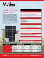
<strong>Mounting</strong> table-1<br />
KD235GX-LFB<br />
KD240GX-LFB<br />
KD245GX-LFB<br />
Long side<br />
Bolting<br />
Top down<br />
clamp<br />
: Permissible<br />
clamping range<br />
281mm 1100mm<br />
100mm 100mm 100mm 100mm<br />
281mm 1100mm<br />
100mm 100mm 100mm 100mm<br />
281mm 1100mm<br />
281mm 1100mm
KKM-SM-0717<br />
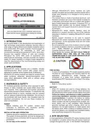
<strong>Mounting</strong> table-2<br />
KD215GX-LFBS<br />
KD220GX-LFBS<br />
Long Side<br />
Short Side<br />
Bolting<br />
278.5mm<br />
943mm<br />
278.5mm<br />
943mm<br />
Top Down<br />
Clamp<br />
:<br />
Permissible<br />
clamping range<br />
100mm 100mm<br />
100mm 100mm<br />
278.5mm<br />
943mm<br />
100mm 200mm<br />
278.5mm<br />
943mm<br />
100mm 200mm<br />
100mm 100mm 100mm 100mm<br />
278.5mm<br />
943mm<br />
943mm<br />
278.5mm<br />
150mm<br />
150mm<br />
150mm<br />
150mm<br />
200mm<br />
100mm<br />
278.5mm<br />
943mm<br />
200mm 100mm<br />
943mm<br />
278.5mm<br />
Continuous<br />
Clamp<br />
:<br />
continuous clamp
KKM-SM-0717<br />
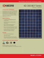
<strong>Mounting</strong> table-3<br />
KD135GX-LFBS<br />
KD140GX-LFBS<br />
Long Side<br />
Short Side<br />
Bolting<br />
278.5mm<br />
943mm<br />
278.5mm<br />
943mm<br />
Top Down<br />
Clamp<br />
:<br />
Permissible<br />
clamping range<br />
100mm<br />
278.5mm<br />
278.5mm<br />
943mm<br />
943mm<br />
100mm<br />
200mm<br />
100mm<br />
100mm<br />
200mm<br />
278.5mm 943mm<br />
278.5mm 943mm<br />
150mm 150mm<br />
150mm<br />
150mm<br />
200mm<br />
278.5mm<br />
943mm<br />
200mm<br />
278.5mm 943mm<br />
Continuous<br />
Clamp<br />
:<br />
continuous clamp