LMA-2 Manual - Innovate Motorsports
LMA-2 Manual - Innovate Motorsports
LMA-2 Manual - Innovate Motorsports

You also want an ePaper? Increase the reach of your titles
YUMPU automatically turns print PDFs into web optimized ePapers that Google loves.
LM-1 RPM Converter (Aux. Input Cable #2)<br />
USER MANUAL
LM-1 Aux Input Cable and RPM Converter<br />
1. Introduction<br />
The LM-1 Aux Input Cable #2 (RPM-converter) is an auxiliary device for the LM-1 Lambda Meter.<br />
The Aux Input Cable allows the connection of up to 5 analog inputs for data logging to the LM-1.<br />
The RPM converter converts RPM pulses from various sources to an analog 0-5V voltage and<br />
allows the connection of up to 4 additional analog inputs for data logging to the LM-1. For details<br />
on the analog signal inputs see chapter 7.<br />
The RPM-converter can either be used with an inductive clamp (similar to an ignition timing light<br />
clamp) or with a pulsed RPM signal from other sources (like tach output signals from ECU's or<br />
electronic ignition systems).<br />
As set up by the factory, the RPM-converter is programmed for 1 pulse for every 2 crank<br />
rotations as can be expected when using the ignition clamp on the spark wire of one cylinder<br />
(non waste-spark ignition).<br />
The RPM-converter can be user-programmed for different numbers of pulses per crank rotation,<br />
as described below.<br />
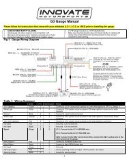
Figure 1. Aux Input Cable #2 (The RPM converter)<br />
The Setup button on the RPM converter is used to program the RPM-converter for different<br />
pulse numbers per crank rotation as described in chapter 6. The Indicator LED will be steadily on<br />
when the RPM-converter detects a valid RPM signal. The Aux 2-5 screw terminals allow the<br />
connection of other sensors from your car.<br />
You can only hook up Aux-input signals whose voltage never<br />
exceeds 5V and does not go below ground. Failure to heed this warning<br />
may cause damage to either the LM-1 or the RPM-converter.
The RPM pulse input is used when using an RPM-pulsed signal other than the inductive clamp.<br />
See chapter 2 for specifics about the RPM pulse input.<br />
The RPM pulse input can be hooked up to the switched terminal of the ignition coil, provided the<br />
ignition system is not a capacitive discharge or multi-spark type.<br />
Be very careful when connecting to the ignition coil. Some ignition<br />
systems retain a high voltage at the ignition coil for a long time even when<br />
the engine is off. This high voltage can kill. Always short the terminal to<br />
ground before you work on it.<br />
2. RPM measurement basics<br />
Most RPM measurement methods use the ignition system of the car as a convenient source of<br />
RPM dependent pulses. Other methods use a TDC sensor (one pulse per rotation), cam sensor,<br />
or fuel injection pulses (number of pulses/rotation is dependent on the fuel-injection system).<br />
Some actually measure the AC frequency created by the car's alternator.<br />
Because the number of pulses per crank rotation is dependent on the ignition system and engine<br />
type, a universal RPM measurement method must be adaptable to the different environments<br />
encountered. The typical ignition system consists of an ignition coil, a coil driver that switches<br />
current to the coil on and off, and a distributor. When current is switched on to the coil, the coil<br />
stores energy in its magnetic field. When the current is switched off, that energy gets discharged<br />
at a very high voltage pulse on the coil’s secondary winding, creating a spark.<br />
A capacitive discharge ignition system (CDI) uses a capacitor to store the spark energy. The<br />
capacitor is charged to about 400V and then rapidly discharged over the ignition coil's primary<br />
winding. The coil thus only acts as transformer and does not store energy (and can therefore be<br />
smaller). The advantage of a CDI system is a very high and fast rising spark voltage (less<br />
susceptible to spark fouling). The weakness of the CDI system is the very short duration spark,<br />
which might not be long enough to ignite the mixture. Multispark ignition systems try to overcome<br />
the inherent weakness by creating multiple spark pulses over some degrees of crank rotation to<br />
increase the likelihood of igniting the mixture. The distributor switches the spark voltage to the<br />
appropriate spark plug.<br />
2.1. Four-Stroke Engines<br />
On a typical 4-stroke engine each spark plug fires once for every two crank rotations.<br />
The coil on a distributor-equipped 4-stroke has to create sparks for every cylinder. The number of<br />
ignition pulses per crank rotation in this case is the number of cylinders divided by 2.<br />
Some engines have one coil for every 2 cylinders instead of a distributor. The coil fires two spark<br />
plugs at the same time. One spark is wasted because it fires one cylinder at the end of its<br />
exhaust stroke. Therefore, this system is called a Waste Spark System. Each coil of a Waste<br />
Spark System fires once for every crank revolution.<br />
Other distributor-less 4-stroke engines use one ignition coil for every spark plug. This ignition<br />
system fires each coil once for every 2 crank revolutions.<br />
Coil-on-Plug ignition systems actually incorporate the ignition coil in a module that plugs directly<br />
onto a spark plug and do not have a spark plug wire.
2.2 Two-Stroke Engines<br />
On a 2-stroke engine there is a spark for every crank rotation, so the spark frequency doubles<br />
compared to a 4-stroke.Very few multi-cylinder 2-strokes have distributors. For those that do, the<br />
number of ignition pulses per crank rotation is equal to the number of cylinders. Most two-stroke<br />
engines have one coil for every cylinder. The coil fires once for every crank revolution, the same<br />
as on a 4-Stroke Waste Spark system.<br />
2.3 Rotary Engines (Wankel Motors)<br />
A rotary engine consists of a roughly triangle shaped rotor rotating in a roughly elliptical chamber.<br />
The three spaces left between the chamber and the rotor go through the four cycles of a fourstroke<br />
engine for each rotation of the rotor. A single (or dual) spark plug at a fixed position in the<br />
chamber ignites the mixture of each space in sequence. Therefore, a rotary engine requires 3<br />
sparks for every rotation of the rotor. The mechanical power from the rotor is coupled to an<br />
eccentric gear to the output shaft. This gear has a 3:1 gear ratio and the output shaft therefore<br />
rotates 3 times faster than the rotor. The output shaft is the equivalent of the crankshaft on a<br />
piston engine. Because RPMs are measured conventionally as the rotations of the crankshaft,<br />
the rotary engine requires one spark for every 'crankshaft' rotation, the same as a two-stroke<br />
engine.<br />
3. Using the RPM-Converter with the Inductive Clamp<br />
The inductive clamp measures the magnetic field created around a spark plug wire when spark<br />
current flows. If a metallic shield covers the spark plug wire, the inductive clamp may not work<br />
because the shield would short out the magnetic field. Like all inductive clamp rpm pickup<br />
devices, some ignition systems like Capacitive Discharge Ignition (CDI) or multi-spark ignition<br />
systems may not work properly with the inductive clamp pickup because the pulses created may<br />
be too short in duration. Multi-spark systems confuse the ignition timing measurement because<br />
the RPM converter cannot distinguish which ignition pulse belongs to which crank rotation. The<br />
RPM converter will work only on the tach output of the ignition system in this case.<br />
The inductive clamp must be clamped around ONE lead only. Clamping it (for example)<br />
around all wires of a coil-on-plug pack does not allow it to work because the magnetic<br />
fields of the wires most likely cancel each other out.
3.1 Inductive Clamp Usage<br />
- Plug the inductive clamp's 3.5mm audio plug into the inductive clamp input of the RPM<br />
converter.<br />
- Clamp the Inductive Clamp on the spark plug wire of one cylinder so the wire is completely<br />
surrounded by the clamp.<br />
- Make sure the clamp is completely closed.<br />
- Plug the RPM-converter in the LM-1 unit.<br />
- Start the engine.<br />
- Switch on the LM-1 unit.<br />
The indicator LED on the RPM-converter should light up steadily. The indicator light indicates<br />
when a valid RPM signal is detected. If it does not light up, or lights up intermittently, reposition or<br />
reverse the clamp (try clamping it upside down). If the LED goes out only occasionally, that is<br />
OK. The RPM converter will still convert, though its output might be noisy. A noisy output has<br />
spikes or lengthy flat areas in the data log. [Note: to work properly with the inductive clamp<br />
pickup the RPM converter must be set up for the appropriate number of pulses per crank<br />
rotation.]<br />
• For a 4 stroke engine without waste spark ignition, this would be 1 pulse per 2 crank<br />
rotations. This is the factory setting.<br />
• For a 4 stroke engine with waste spark ignition, or a 2 stroke engine, this would be 1 pulse<br />
per crank rotation.<br />
• For a rotary engine, this would be 3 pulses per rotation. This is the same as for a 6-cyl 4-<br />
stroke before the distributor.<br />
Note: On any distributor-less ignition system you can alternately clamp the inductive<br />
clamp around one of the power wires on the primary side of the ignition coil or coil-onplug<br />
module.<br />
4. Using the RPM-Converter with pulsed RPM input (Tach) signals<br />
- Unplug the inductive clamp from the RPM converter if connected.<br />
- Connect the RPM signal to the RPM pulse input screw terminal.<br />
- Plug the RPM-converter into the LM-1 unit.<br />
- Start the engine.<br />
- Switch on the LM-1 unit.<br />
The indicator LED on the RPM-converter should light up steadily. The indicator light indicates<br />
when a valid rpm signal is detected. If it does not light up, check your connections.<br />
DO NOT CONNECT A PULSED RPM SIGNAL TO THE INDUCTIVE CLAMP INPUT. THIS<br />
MIGHT DAMAGE THE RPM-CONVERTER OR LM-1. Again, this should just result in an<br />
error code, not mechanical damage.<br />
In most cases the ground connection of the RPM converter is required only if the other Aux<br />
Inputs (2-5) are used.
5. Setup of the RPM-Converter for different rpm pulses/rotation<br />
During the setup procedure the RPM converter measures the number of pulses for 5 seconds.<br />
Then it selects from a table the closest matching engine setup. If the measured pulses cannot be<br />
found in the table, the RPM converter retains the previous setting. The table covers the following<br />
engines:<br />
# of Type of Pulses/Crank Notes<br />
Cylinders Engine Rotation<br />
1 4 Stroke 1/2<br />
1 2 Stroke 1 Or waste spark ignition connected to one<br />
spark wire or coil<br />
1 Rotor Rotary 1<br />
2 2 Stroke 2<br />
4 4 Stroke 2<br />
4 2 Stroke 4<br />
5 4 Stroke 2 1/2<br />
5 2 Stroke 5<br />
6 4 Stroke 3<br />
6 2 Stroke 6<br />
8 4 Stroke 4<br />
8 2 Stroke 8<br />
10 4 Stroke 5<br />
12 4 Stroke 6<br />
12 2 Stroke 12<br />
So the table consists of engine/ignition types of:<br />
1/2, 1, 2, 2-1/2, 3, 4, 5, 6, 8 and 12 pulses per crank rotation<br />
5.1 Setup using the audio output of your computer (preferred method)<br />
Required:<br />
- A computer with a sound output.<br />
- A 3.5mm (1/8") Stereo cable to connect the sound card speaker or headset output to the<br />
inductive clamp Input of the RPM converter.<br />
- LM Programmer PC Software Version 2.0 or later (LMConfig Version 1.21 or later.) (Available at<br />
http://www.innovatemotorsports.com/support/download.php ).<br />
Preparation:<br />
- Connect the RPM-Converter to the LM-1 unit.<br />
- Connect the serial cable of the LM-1 unit to your computer.<br />
- Connect the stereo cable between the speaker or headset output of your computer and the<br />
inductive clamp Input of the RPM-Converter.<br />
- Make sure no background sound is playing on your computer. No CD or MP3’s playing to the<br />
RPM-Converter, please.<br />
- Switch on the LM-1 unit.<br />
- If your computer has a sound volume control, make sure it is set all the way up.<br />
- Start the LM Programmer application (LMConfig prior to version 2.0).<br />
- Click the RPM Tab. The RPM-Converter setup page looks like this:
Figure 3. RPM-Converter Setup Page<br />
Select the engine type and number of pulses per crank rotation. Then press the setup button.<br />
Follow the instructions provided on screen. After the setup is complete, the LED on the RPMconverter<br />
should light up steadily. To test your setup, press the 'Test' button. The LED on the<br />
RPM-Converter should light up for about 4 seconds.<br />
To test your sound output, connect the regular speakers back to your computer. Then select '4-<br />
Stroke', uncheck 'Waste Spark', select Ignition Pulses and set the number of Cylinders to 12.<br />
Then press the 'Test' button. You should hear a loud tone of about 440 Hz (Middle A). The output<br />
frequency is set to simulate 4400 RPM for the selected engine type.<br />
5.2 Auto-configuration using your engine<br />
- Connect and power up the LM-1 and RPM-Converter as described in Chapter 4.- Make sure the<br />
Indicator LED is lighting up steadily at 2000 RPM.<br />
- Press and hold the Setup button on the RPM-Converter until the Indicator LED on the RPM-<br />
Converter blinks rapidly.<br />
- You have now 10 seconds to rev up your engine to 2000 RPM while the Indicator LED blinks<br />
rapidly.<br />
- Hold the engine at 2000 RPM ( +- 200 RPM) while the Indicator LED blinks. When it starts to<br />
blink slowly it is taking measurements.<br />
- After a total of 15 seconds the Indicator LED will light up steadily.<br />
- Relax, you are done.<br />
The RPM Converter accurately tracks RPM signal up to a limit of 10230 RPM. If your engine is<br />
expected to rev higher than 10230 RPMs in operation, hold the engine at 4000 RPM (+- 400<br />
RPM) instead of 2000. The datalog will still be showing 0-10230 RPMs, just double the values in<br />
the data log or change the setup using the custom setup procedure as described in the LM-1<br />
manual. This procedure works only for pulsed rpm signals of up to 6 pulses per crank rotation.
6. RPM Converter Specification<br />
Min Typical Max Unit<br />
Measurable RPM (Note1) 100 10,230 RPM<br />
Input frequency 0.8 1100 Hz<br />
Input Pulse Amplitude 1.5 250 V<br />
Input Impedance (RPM input) 10 kOhm<br />
Input Impedance (Aux inputs) 2 MOhm<br />
Minimum Input pulse width 0.1 usec<br />
Measurement error (Note 2) 1.0 % of indicated<br />
Resolution (Note3) 10 RPM<br />
RPM-output rise/fall time 0.04 sec/1000<br />
RPM<br />
Overswing 20 RPM<br />
Power consumption (5V) 10 mA<br />
Cable Length 6 ft.<br />
Housing Size (LxWxH) 4.175 x 1.75x0.6 in.<br />
Note1: When calibrated with 4000 RPM instead of 2000 RPM, max RPM is 20,460.<br />
Note2: or 50 RPM, whichever is greater.<br />
Note3: When calibrated with 4000 RPM instead of 2000 RPM, resolution is 20 RPM.<br />
7. Auxiliary Inputs<br />
The Auxiliary Inputs of the RPM-Converter cable or the Aux Input cable are used to connect other<br />
signals from the car to the LM-1 for data logging. The procedure is the same for all inputs.<br />
When connecting signals to the Auxiliary inputs, connect the Ground of the Aux Input Cable (or<br />
RPM converter) as close as possible to the sensor from which you want the highest resolution.<br />
Ground differences between sensors can falsify the results. Ground differences can be as large<br />
as 0.5V, which is 10% of the input range. The Auxiliary inputs have an input impedance (static) of<br />
greater than 1 MOhm.<br />
You can only hook up Aux-input signals whose voltage never<br />
exceeds 5 V and does not go below ground. Failure to heed this warning<br />
may cause irreparable damage to either the LM-1 or the RPM-converter.<br />
Typical sensors like MAP sensors or TPS sensor output signals vary with the measured quantity.<br />
If the Aux Inputs are used to measure switched signals involving coils like solenoids or relays,<br />
special protection devices should be added. The following example describes using an Aux<br />
Input to record the state of a NOS solenoid. The same protection method can be used for other<br />
solenoids or relays or other switched signals that exceed the 5V input limit of the Aux inputs.
7.1 Recording the state of a NOS solenoid<br />
Figure 4. Solenoid Interface (High Side Switch, Low Side Switch)<br />
or<br />
In the left case the solenoid is grounded on one side, the other side is switched to 12V when the<br />
solenoid is on. The LM-1 will record 3.3V when the solenoid is on, and record 0V when the<br />
solenoid is off. In the second case the solenoid is connected to 12V on one side and the other<br />
side will be grounded when the solenoid is on. The LM-1 will record 0V when the solenoid is on<br />
and 3.3V when the solenoid is off. The same method can also be used to detect other signals like<br />
clutch switch and so on.<br />
7.2 Recording Battery voltage or a signal between 0 and 12V<br />
This circuit creates a load of 330 kOhm on the signal. If your measured signal has a high output<br />
impedance (> 33 kOhm), increase the resistor values in the circuit proportionally.<br />
Figure 5. Battery Voltage or high signal amplitude interface<br />
The measured signal is divided by 3. The maximum battery voltage that can be measured is 15V.<br />
The recorded voltage will be 1/3 of the actual voltage. Either multiply the measured voltage in the<br />
log by 3 or set up the appropriate input as custom as described in the LM-1 manual.<br />
8.1 Revision History<br />
Version 1.0- November 20, 2003- Initial Release<br />
Version 1.1 – December 10, 2003<br />
Version 1.2 – May 12, 2004 –Update LM Programmer screen shots and references