HAYNES ® 214 ® alloy Brochure - Haynes International, Inc.
HAYNES ® 214 ® alloy Brochure - Haynes International, Inc.
HAYNES ® 214 ® alloy Brochure - Haynes International, Inc.

Create successful ePaper yourself
Turn your PDF publications into a flip-book with our unique Google optimized e-Paper software.
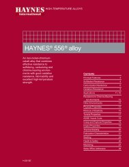
HIGH-TEMPERATURE ALLOYS<br />
<strong>HAYNES</strong> <strong>®</strong> <strong>214</strong> <strong>®</strong> ALLOY<br />
A nickel-chromium-aluminumiron<br />
<strong>alloy</strong> with outstanding<br />
resistance to oxidation.<br />
Contents<br />
Typical Applications 2<br />
Principal Features 3<br />
Oxidation Resistance 4<br />
Carburization Resistance 7<br />
Resistance to Chlorine-Bearing<br />
Environments 10<br />
Nitriding Resistance 11<br />
Physical Properties 12<br />
Modulus of Elasticity 13<br />
Tensile Properties 14<br />
Creep and Rupture Properties 15<br />
Thermal Stability 16<br />
Fabrication Characteristics 16<br />
Welding<br />
17<br />
Health & Safety 19<br />
Sales Office Addresses 20<br />
H-3008D
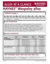
APPLICATIONS<br />
<strong>HAYNES</strong> <strong>®</strong> <strong>214</strong> <strong>®</strong> <strong>alloy</strong> is gaining rapid acceptance for<br />
use in honeycomb seals because of its outstanding<br />
oxidation resistance. The seals are made of thin<br />
gage foil and are used to prevent leakage between<br />
different stages in gas turbine engines. Such seals<br />
contribute to an engines fuel efficiency.<br />
This <strong>214</strong> <strong>alloy</strong> flamehood remained in service for 16<br />
months in an application where other nickel <strong>alloy</strong><br />
hoods required replacement every three to four<br />
months. The <strong>alloy</strong> component was subjected to<br />
direct flame impingement during the entire period in<br />
an automotive products plant.<br />
Section of a <strong>214</strong> <strong>alloy</strong> belt which was removed<br />
after 3,000 hours at 1800°F (980°C) in a chinaware<br />
decorating kiln. The belt showed only minimal<br />
wear and oxidation attack. Use of <strong>214</strong> <strong>alloy</strong> in<br />
this application has helped reduce the time of the<br />
operation from eight or twelve hours, to less than<br />
30 minutes.<br />
The burner assembly at left failed after 450 cycles<br />
between minus 55 and 2000°F (minus 50 and<br />
1095°C.) A <strong>214</strong> <strong>alloy</strong> burner was still in good shape<br />
after 2000 cycles in the same test. The burners<br />
were cycled from low to high temperatures in about<br />
five minutes, held for a 15-minute burn, and then<br />
rapid-air cooled.<br />
<strong>Haynes</strong> <strong>®</strong> <strong>214</strong> <strong>®</strong> <strong>alloy</strong><br />
2<br />
©2008 <strong>Haynes</strong> <strong>International</strong>, <strong>Inc</strong>.
PRINCIPAL FEATURES<br />
Excellent Oxidation<br />
Resistance<br />
<strong>HAYNES</strong> <strong>®</strong> <strong>214</strong> <strong>®</strong> <strong>alloy</strong> is a nickel<br />
- chromium-aluminum-iron <strong>alloy</strong>,<br />
designed to provide the optimum<br />
in high-temperature oxidation<br />
resistance for a wrought austenitic<br />
material, while at the same time<br />
allowing for conventional forming<br />
and joining. Intended principally<br />
for use at temperatures of 1750°F<br />
(955°C) and above, <strong>214</strong> <strong>alloy</strong><br />
exhibits resistance to oxidation<br />
that far exceeds virtually all<br />
conventional heat-resistant wrought<br />
<strong>alloy</strong>s at these temperatures. This<br />
is attributable to the formation<br />
of a tightly adherent Al 2<br />
O 3<br />
-type<br />
protective oxide scale, which forms<br />
in preference to chromium oxide<br />
scales at these high temperatures. At<br />
temperatures below 1750°F (955°C),<br />
<strong>214</strong> <strong>alloy</strong> develops an oxide scale<br />
which is a mixture of chromium and<br />
aluminum oxides. This mixed scale<br />
is somewhat less protective, but still<br />
affords <strong>214</strong> <strong>alloy</strong> oxidation resistance<br />
equal to the best nickel-base <strong>alloy</strong>s.<br />
The higher temperature Al 2<br />
O 3<br />
- type<br />
scale which <strong>214</strong> <strong>alloy</strong> forms also<br />
provides the <strong>alloy</strong> with excellent<br />
resistance to carburization, nitriding<br />
and corrosion in chlorine-bearing<br />
oxidizing environments.<br />
Fabrication<br />
<strong>HAYNES</strong> <strong>214</strong> <strong>alloy</strong> is similar in<br />
many respects to high aluminum<br />
content nickel-base <strong>alloy</strong>s which<br />
are intended to be age-hardened<br />
by intermediate temperature<br />
heat treatment. If exposed at<br />
temperatures in the range of 1100-<br />
1700°F (595-925°C), <strong>214</strong> <strong>alloy</strong><br />
will exhibit age-hardening as a<br />
result of the formation of a second<br />
phase, gamma prime (Ni 3<br />
Al). This<br />
also results in a significant loss of<br />
intermediate and low temperature<br />
tensile ductility. As a consequence<br />
of this, <strong>214</strong> <strong>alloy</strong> is susceptible to<br />
strain-age cracking when highlystressed,<br />
highly-restrained, welded<br />
components are slowly heated<br />
through the intermediate temperature<br />
regime. This behavior is the same<br />
as that exhibited by high aluminum<br />
+ titanium content super<strong>alloy</strong>s, such<br />
as Waspaloy or R-41 <strong>alloy</strong>s. The<br />
keys avoiding this problem are to<br />
minimize weldment restraint through<br />
appropriate component design, and/<br />
or heat rapidly through the 1100-<br />
1700°F (595-925°C) temperature<br />
range during post-fabrication heat<br />
treatment (or first use heat up).<br />
With the exception of the above<br />
consideration, <strong>HAYNES</strong> <strong>214</strong> <strong>alloy</strong><br />
does exhibit good forming and<br />
welding characteristics. It may be<br />
forged or otherwise hot-worked,<br />
providing it is held at 2100°F<br />
(1150°C) for a time sufficient to bring<br />
the entire piece to temperature. Its<br />
room temperature tensile ductility<br />
is also high enough to allow the<br />
<strong>alloy</strong> to be formed by coldworking.<br />
All cold or hot-worked parts should<br />
be annealed and rapidly cooled in<br />
order to restore the best balance of<br />
properties.<br />
The <strong>alloy</strong> can be welded by a<br />
variety of techniques, including gas<br />
tungsten arc (TIG), gas metal arc<br />
(MIG) or shielded metal arc (coated<br />
electrode) welding.<br />
Heat-Treatment<br />
<strong>HAYNES</strong> <strong>214</strong> <strong>alloy</strong> is furnished in<br />
the solution heat-treated condition,<br />
unless otherwise specified. The <strong>alloy</strong><br />
is normally solution heat-treated at<br />
2000°F (1095°C) and rapidly cooled<br />
or quenched for optimum properties.<br />
Heat treating at temperatures<br />
below the solution heat-treating<br />
temperature will result in grain<br />
boundary carbide precipitation and,<br />
below 1750°F (955°C), precipitation<br />
of gamma prime phase. Such lower<br />
temperature agehardening heat<br />
treatments are not suggested.<br />
Available Product Forms<br />
<strong>HAYNES</strong> <strong>214</strong> <strong>alloy</strong> is available in the<br />
form of plate, sheet, strip, billet, bar,<br />
and wire.<br />
Applicable<br />
Specifications<br />
<strong>HAYNES</strong> <strong>214</strong> <strong>alloy</strong> is covered by<br />
DIN specification number 17744<br />
No.2.4646 for all forms, and a full<br />
range of <strong>Haynes</strong> internal product<br />
specifications. Please consult<br />
<strong>Haynes</strong> <strong>International</strong> for details.<br />
Applications<br />
<strong>HAYNES</strong> <strong>214</strong> <strong>alloy</strong> combines<br />
properties which make it very<br />
suitable for service in relatively<br />
low-stress, high temperature<br />
oxidizing environments, where the<br />
utmost in resistance to oxidation<br />
or scale exfoliation is needed. Its<br />
resistance to such environments<br />
persists to temperatures as high as<br />
2400°F (1315°C), although strength<br />
limitations may apply. Applications<br />
can include “Clean Firing” uses such<br />
as mesh belts, trays and fixtures<br />
for firing of pottery and fine china,<br />
and the heat treatment of electronic<br />
devices and technical grade<br />
ceramics.<br />
In the gas turbine industry, <strong>214</strong><br />
<strong>alloy</strong> is used for foil construction<br />
honeycomb seals, combustor splash<br />
plates, and other static oxidation<br />
- limited parts. The automotive<br />
industry has applications for <strong>214</strong><br />
<strong>alloy</strong> in catalytic converter internals,<br />
and it is used as a burner cup<br />
material in auxiliary heaters for<br />
military vehicles.<br />
In the industrial heating market, <strong>214</strong><br />
<strong>alloy</strong> is used for highly specialized<br />
applications such as refractory<br />
anchors, furnace flame hoods,<br />
and rotary calciners for processing<br />
chloride compounds. It is also<br />
used for parts in high temperature<br />
chlorine-contaminated environments,<br />
such as hospital waste incinerator<br />
internals.<br />
Nominal Chemical Composition, Weight Percent<br />
Ni Cr Al Fe Mn Si Zr C B Y<br />
75 a 16 4.5 3 0.5* 0.2* 0.1* 0.05 0.01* 0.01<br />
a<br />
As Balance *Maximum<br />
3 <strong>Haynes</strong> <strong>®</strong> <strong>214</strong> <strong>®</strong> <strong>alloy</strong>
OXIDATION RESISTANCE<br />
<strong>HAYNES</strong> <strong>214</strong> <strong>alloy</strong> provides resistance<br />
to oxidation at temperatures of 1750°F<br />
(955°C) and above that is virtually<br />
unmatched by any other wrought<br />
heat-resistant <strong>alloy</strong>. It can be used<br />
for long-term continuous exposure<br />
to combustion gases or air at<br />
temperatures up to 2300°F (1260°C),<br />
and, for shorter term exposures, it can<br />
be used at even higher temperatures.<br />
Useful short-term oxidation resistance<br />
has even been demonstrated at<br />
temperatures as high as 2400°F<br />
(1315°C).<br />
Comparative Oxidation Resistance in Flowing Air*<br />
average Metal Affected in 1008 Hours**<br />
1800°F (980°C) 2000°F (1095°C) 2100°F (1150°C) 2200°F (1205°C)<br />
Material Mils µm Mils µm Mils µm Mils µm<br />
<strong>214</strong> <strong>®</strong> <strong>alloy</strong> 0.2 5 0.1 3 0.3 8 0.7 18<br />
230 <strong>®</strong> <strong>alloy</strong> 0.7 18 1.3 33 3.4 86 7.9 201<br />
<strong>alloy</strong> 600 0.9 23 1.6 41 2.9 74 8.4 213<br />
<strong>alloy</strong> 601 1.3 33 2.6 66 5.3 135 7.5*** 191***<br />
RA330 <strong>®</strong> <strong>alloy</strong> 4.3 109 6.7 170 8.7 221 - -<br />
<strong>alloy</strong> 800H 1.8 46 7.4 188 8.9 226 13.6 289<br />
Type 446 SS 2.3 58 14.5 368 >21.7 >551 >23.3 >592<br />
Type 316 SS 14.3 363 >68.4 >1737 >105.0 >2667 >140.4 >3566<br />
* Flowing air at a velocity of 7.0 feet/minute (213.4 cm/minute) past the samples. Samples cycled to room temperature once-a-week.<br />
** Metal Loss + Average Internal Penetration<br />
*** 601 Sample exhibited very large internal voids.<br />
Metallographic Technique used for Evaluating Environmental Tests<br />
1. Metal Loss = (A - B)/2<br />
2. Average Internal Penetration = C<br />
3. Maximum Internal Penetration = D<br />
4. Average Metal Affected = ((A - B)/2) + C<br />
5. Maximum Metal Affected = (A - B)/2) + D<br />
<strong>Haynes</strong> <strong>®</strong> <strong>214</strong> <strong>®</strong> <strong>alloy</strong><br />
4
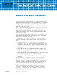
Comparative Oxidation in Flowing Air 2100°F (1150°C)<br />
Microstructures shown are for<br />
coupons exposed for 1008<br />
hours at 2100°F (1150°C) in<br />
air flowing at 7.0 feet/minute<br />
(213.4 cm/minute) past the<br />
samples. Samples were<br />
descaled by cathodically<br />
charging the coupons while<br />
they were immersed in a<br />
molten salt solution. The black<br />
area shown at the top of each<br />
picture represents actual metal<br />
loss due to oxidation. The<br />
data clearly show <strong>HAYNES</strong> <strong>®</strong><br />
<strong>214</strong> <strong>®</strong> <strong>alloy</strong> is only slightly<br />
affected by the exposure,<br />
while other nickel-chromium<br />
<strong>alloy</strong>s, such as <strong>alloy</strong>s 600 and<br />
601, and ironnickel chromium<br />
<strong>alloy</strong>s, such as RA330 <strong>®</strong> <strong>alloy</strong>,<br />
all exhibit significantly more<br />
oxidation damage. Of particular<br />
importance is the almost total<br />
absence of internal attack for<br />
the <strong>214</strong> <strong>alloy</strong>. This contrasts<br />
markedly with the very<br />
substantial amount of internal<br />
attack evidenced by the <strong>alloy</strong><br />
601 and RA330 <strong>alloy</strong> tests<br />
coupons. The nature of this<br />
internal attack, as illustrated<br />
by the photomicrographs, is<br />
common for <strong>alloy</strong>s containing<br />
1-2% aluminum or silicon. Such<br />
levels of these elements do<br />
promote chromium oxide scale<br />
adherence, but do not afford<br />
improved resistance to oxide<br />
penetration below the scale.<br />
<strong>HAYNES</strong> <strong>®</strong> <strong>214</strong> <strong>®</strong> <strong>alloy</strong><br />
Average Metal Affected<br />
= 0.3 Mils (8 µm)<br />
Alloy 600<br />
Average Metal Affected<br />
= 2.9 Mils (74 µm)<br />
Alloy 601<br />
Average Metal Affected<br />
= 5.3 Mils (135 µm)<br />
200 µm<br />
RA330 <strong>alloy</strong><br />
Average Metal Affected<br />
= 8.7 Mils (221 µm)<br />
5 <strong>Haynes</strong> <strong>®</strong> <strong>214</strong> <strong>®</strong> <strong>alloy</strong>
Comparative Burner Rig Oxidation Resistance<br />
1800°F (980°C)/1000 Hours 2000°F (1095°C)/500 Hours<br />
Metal Loss Av. Metal Affected* Metal Loss Av. Metal Affected*<br />
Material Mils µm Mils µm Mils µm Mils µm<br />
<strong>214</strong> <strong>®</strong> <strong>alloy</strong> 0.4 10 1.0 25 0.5 13 1.2 30<br />
230 <strong>®</strong> <strong>alloy</strong> 0.8 20 2.8 71 2.2 56 5.2 132<br />
X <strong>alloy</strong> 2.7 69 5.6 142 9.0 229 12.9 328<br />
RA330 <strong>®</strong> <strong>alloy</strong> 7.8 198 11.8 300 10.9 277 12.9 328<br />
<strong>alloy</strong> 600 12.3 a 312 a 14.4 a 366 a 17.2 437 19.5 495<br />
<strong>alloy</strong> 800H 12.3 312 14.5 368 30.5 b 775 b 33.4 b 848 b<br />
Type 310 Stainless 13.7 348 16.2 411 21.2 538 23.7 602<br />
<strong>alloy</strong> 601 3.0 76 18.8 478 10.7 272 >24.0 c >610 c<br />
* Metal Loss + Average Internal Penetration<br />
a<br />
Extrapolated from 917 hours<br />
b<br />
Extrapolated from 400 hours<br />
c<br />
Internal penetration through entire thickness<br />
Oxidation Test Parameters<br />
Burner rig oxidation tests were<br />
conducted by exposing, in a rotating<br />
holder, samples 0.375 inch x 2.5<br />
inches x thickness (9.5mm x 64mm<br />
x thickness) to the products of<br />
combustion of fuel oil (2 parts No. 1<br />
and 1 part No. 2) burned at a ratio of<br />
air to fuel of about 50:1. (Gas velocity<br />
was about 0.3 mach). Samples were<br />
automatically removed from the gas<br />
stream every 30 minutes and fan<br />
cooled to less than 500°F (260°C) and<br />
then reinserted into the flame tunnel.<br />
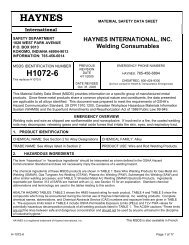
Comparative Burner Rig Oxidation Resistance at 1800°F (980°C)/1000 Hours<br />
(Black areas of micros indicates actual metal loss)<br />
<strong>HAYNES</strong> <strong>®</strong> <strong>214</strong> <strong>®</strong> <strong>alloy</strong><br />
Average Metal Affected<br />
= 1.0 Mils (25 µm)<br />
Alloy 601<br />
Average Metal Affected<br />
= 18.8 Mils (478 µm)<br />
RA330 <strong>alloy</strong><br />
Average Metal Affected<br />
= 11.8 Mils (300 µm)<br />
Alloy 800H<br />
Average Metal Affected<br />
= 14.5 Mils (368 µm)<br />
Comparative Burner Rig Oxidation Resistance at 2000°F (1095°C)/500 Hours<br />
200 µm<br />
<strong>HAYNES</strong> <strong>®</strong> <strong>214</strong> <strong>®</strong> <strong>alloy</strong><br />
Average Metal Affected<br />
= 1.2 Mils (30 µm)<br />
Alloy 601<br />
Average Metal Affected<br />
= >24.0 Mils (>610 µm)<br />
RA330 <strong>alloy</strong><br />
Average Metal Affected<br />
= 12.9 Mils (328 µm)<br />
Alloy 800H<br />
Average Metal Affected<br />
= 33.4 Mils (848 µm)<br />
<strong>Haynes</strong> <strong>®</strong> <strong>214</strong> <strong>®</strong> <strong>alloy</strong><br />
6
CARBURIZATION RESISTANCE<br />
<strong>HAYNES</strong> <strong>214</strong> <strong>alloy</strong> has very good<br />
resistance to carburization, as<br />
measured in both packed graphite<br />
exposure tests and mixed gas<br />
exposure tests. Results for these tests<br />
are presented in the following pages.<br />
All results are presented in terms of<br />
the mass of carbon absorption per<br />
unit area, which was obtained from<br />
the equation M = C(W/A) where M =<br />
the mass of carbon absorption per<br />
unit area (mg/cm 2 ). C = difference in<br />
carbon (weight fraction) before and<br />
after exposure, W = weight of the<br />
unexposed specimen (mg) and A =<br />
surface area of the specimen exposed<br />
to the test environment (cm 2 ).<br />
Packed Carburization Resistance<br />
Carbon absorption observed for <strong>214</strong><br />
<strong>alloy</strong> following 500 hour exposure in<br />
packed graphite at 1800°F (980°C)<br />
was very low, as shown below.<br />
While superior resistance was<br />
exhibited by <strong>HAYNES</strong> HR-120<br />
and 556 <strong>alloy</strong>s, other <strong>alloy</strong>s tested<br />
exhibited significantly greater carbon<br />
absorption. In particular, the resistance<br />
to carburization of <strong>214</strong> <strong>alloy</strong> was far<br />
better than that for the stainless steel<br />
type materials.<br />
12<br />
10<br />
500 Hours @ 1800°F (980°C)<br />
in packed graphite<br />
Carbon Absorption (mg/cm 2<br />
8<br />
6<br />
4<br />
2<br />
0<br />
HR-120 <strong>®</strong> 556 <strong>®</strong> 230 <strong>®</strong> <strong>214</strong> <strong>®</strong> <strong>alloy</strong> RA330 <strong>®</strong> 310 253 MA <strong>®</strong><br />
<strong>alloy</strong> <strong>alloy</strong> <strong>alloy</strong> <strong>alloy</strong> 601 <strong>alloy</strong> <strong>alloy</strong> <strong>alloy</strong><br />
Mixed Gas Carburization Tests<br />
Carbon absorption observed for<br />
<strong>214</strong> <strong>alloy</strong> following exposure at both<br />
1700°F (925°C) and 1800°F (980°C)<br />
to a carburizing gas mixture was<br />
significantly lower than that for all<br />
other materials tested. This is shown<br />
in the graphs on the following pages.<br />
For these tests, the exposure was<br />
performed in a gas environment<br />
consisting of (by volume %) 5.0% H 2<br />
,<br />
5.0% CO, 5.0% CH 4<br />
and the balance<br />
argon. The calculated equilibrium<br />
composition for the test environments<br />
are shown together with the results on<br />
the following pages.<br />
7 <strong>Haynes</strong> <strong>®</strong> <strong>214</strong> <strong>®</strong> <strong>alloy</strong>
Comparative 1700°F (925°C) Mix Gas Carburization Tests<br />
The calculated equilibrium<br />
composition (volume %) at 1700°F<br />
(925°C) and one atma was 14.2%<br />
H 2<br />
, 4.74% CO, 0.0044% CO 2 , 0.032<br />
CH 4<br />
and balance Argon. The activity<br />
of Carbon was 1.0 and the partial<br />
pressure of Oxygen was 2.47 x 10 -22<br />
atma.<br />
<strong>HAYNES</strong> <strong>®</strong> <strong>214</strong> <strong>®</strong> <strong>alloy</strong><br />
1700°F (925°C) for 215 Hours<br />
<strong>HAYNES</strong> <strong>®</strong> 556 <strong>®</strong> <strong>alloy</strong><br />
Alloy 800H<br />
Alloy 600<br />
HASTELLOY <strong>®</strong> X <strong>alloy</strong><br />
INCONEL <strong>alloy</strong> 601<br />
INCONEL <strong>alloy</strong> 617<br />
Type 310 Stainless Steel<br />
1 2 3 4 5 6 7<br />
Carbon Absorption Per Unit Area (mg/cm 2 )<br />
Typical Carburized Microstructures (Unetched) After Exposure<br />
For 215 Hours At 1700°F (925°C)<br />
200 µm<br />
<strong>HAYNES</strong> <strong>®</strong> <strong>214</strong> <strong>®</strong> <strong>alloy</strong><br />
Type 310 Stainless Steel<br />
<strong>Haynes</strong> <strong>®</strong> <strong>214</strong> <strong>®</strong> <strong>alloy</strong><br />
8
Comparative 1800°F (980°C) Mixed Gas Carburization Tests<br />
The calculated equilibrium<br />
composition (volume %) at 1800°F<br />
(980°C) and one atma was 14.2% H 2<br />
,<br />
4.75% CO, 0.0021% CO 2<br />
, 0.024%<br />
CH 4<br />
, 0.0098% H 2<br />
O and balance<br />
argon. The activity of Carbon was 1.0<br />
and the partial pressure of Oxygen<br />
was 6.78 x 10 -22 atma.<br />
Comparative 1800°F (980°C) Mixed Gas Carburization Tests<br />
1800°F (980°C) for 55 Hours<br />
<strong>HAYNES</strong> <strong>®</strong> <strong>214</strong> <strong>®</strong> <strong>alloy</strong><br />
Alloy 800H<br />
<strong>HAYNES</strong> <strong>®</strong> <strong>214</strong> <strong>alloy</strong><br />
Alloy 800H<br />
1800°F (980°C) for 55 hours<br />
<strong>HAYNES</strong> <strong>®</strong> 556 <strong>®</strong> <strong>alloy</strong><br />
<strong>HAYNES</strong> 556 <strong>alloy</strong><br />
HASTELLOY <strong>®</strong> X <strong>alloy</strong><br />
Alloy 600<br />
HASTELLOY X <strong>alloy</strong><br />
Alloy 600<br />
INCONEL <strong>alloy</strong> 617<br />
1 2 3 4<br />
5 6<br />
7<br />
Carbon Absorption Per Unit Area (mg/cm 2 )<br />
INCONEL <strong>alloy</strong> 601<br />
INCONEL <strong>alloy</strong> 617<br />
1 2 3 4 5 6 7<br />
INCONEL <strong>alloy</strong> 601<br />
Carbon Absorption Per Unit Area (mg/cm Typical 2 ) Carburized Microstructures (Unetched) After Exposure<br />
For 55 Hours At 1800°F (980°C)<br />
Typical Carburized Microstructures (Unetched) After Exposure<br />
For 55 Hours At 1800°F (980°C)<br />
<strong>HAYNES</strong> <strong>214</strong> <strong>alloy</strong> INCONEL <strong>alloy</strong> 617<br />
Note: Alloy 617 is carburized to the center of the sample.<br />
200 µm<br />
<strong>HAYNES</strong> <strong>®</strong> <strong>214</strong> <strong>®</strong> <strong>alloy</strong> INCONEL <strong>alloy</strong> 617<br />
Note: Alloy 617 is carburized to the center of the sample.<br />
9 9 <strong>HAYNES</strong> <strong>214</strong> <strong>alloy</strong><br />
<strong>Haynes</strong> <strong>®</strong> <strong>214</strong> <strong>®</strong> <strong>alloy</strong>
RESISTANCE TO CHLORINE-BEARING ENVIRONMENTS<br />
<strong>HAYNES</strong> <strong>214</strong> <strong>alloy</strong> provides<br />
outstanding resistance to corrosion<br />
in high-temperature, chlorinecontaminated<br />
oxidizing environments.<br />
This is particularly evident for<br />
exposures at temperatures at or above<br />
1800°F (980°C), where the formation<br />
of the Al 2<br />
O 3<br />
-rich protective oxide scale<br />
is favored. Test results are shown for<br />
400 hour exposures in a flowing gas<br />
mixture of Ar + 20% O 2<br />
+ 0.25% Cl 2<br />
.<br />
Note that the metal loss exhibited<br />
by <strong>214</strong> <strong>alloy</strong> is very low compared to<br />
other <strong>alloy</strong>s tested.<br />
14<br />
Average<br />
Internal<br />
Penetration<br />
Ar-20%O 2<br />
-0.25%Cl 2<br />
for 400 Hours<br />
1650°F (900°C)<br />
C-276<br />
350<br />
Average Metal Affected (mils)<br />
12<br />
10<br />
8<br />
6<br />
4<br />
Metal Loss<br />
<strong>214</strong> <strong>®</strong> 556 <strong>®</strong> 600<br />
601<br />
625<br />
300<br />
250<br />
200<br />
150<br />
100<br />
Average Metal Affected (µm)<br />
2<br />
50<br />
18<br />
Ar-20%O 2<br />
-0.25%Cl 2<br />
for 400 Hours<br />
625<br />
C-276<br />
450<br />
16<br />
1830°F (1000°C)<br />
600<br />
400<br />
14<br />
350<br />
Average Metal Affected (mils)<br />
12<br />
10<br />
8<br />
6<br />
556 <strong>®</strong><br />
601<br />
300<br />
250<br />
200<br />
150<br />
Average Metal Affected (µm)<br />
4<br />
100<br />
2<br />
<strong>214</strong> <strong>®</strong><br />
50<br />
<strong>Haynes</strong> <strong>®</strong> <strong>214</strong> <strong>®</strong> <strong>alloy</strong><br />
10
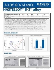
Resistance to Chlorine-Bearing Environments (continued)<br />
<strong>HAYNES</strong> <strong>®</strong> <strong>214</strong> <strong>®</strong> <strong>alloy</strong> has also been<br />
tested in environments with higher<br />
levels of chlorine contamination.<br />
The photomicrographs to the<br />
right are for samples exposed to<br />
a mixture of air and 2% chlorine<br />
for 50 hours at 1830°F (1000°C).<br />
Once again, the black area at the<br />
top of each photograph represents<br />
actual metal loss experience. Alloy<br />
601 exhibited 2.0 Mils (51 µm) of<br />
metal loss, and an average internal<br />
penetration of 6.0 Mils (152 µm),<br />
for a total average metal affected of<br />
8.0 Mils (203 µm). Results for <strong>214</strong><br />
<strong>alloy</strong>, by contrast, were 1.0 Mils (25<br />
µm) of metal loss, 1.0 Mils (25 µm)<br />
of average internal penetration, for<br />
a total average metal affected of<br />
only 2.0 Mils (51 µm). These results<br />
are consistent with the results for<br />
lower chlorine level, longer-term<br />
tests given on the previous page.<br />
Alloy 601<br />
200 µm<br />
<strong>HAYNES</strong> <strong>®</strong> <strong>214</strong> <strong>®</strong> <strong>alloy</strong><br />
NITRIDING RESISTANCE<br />
While not the most resistant <strong>alloy</strong> for<br />
nitriding environments at traditional<br />
1000°F to 1200°F (540°C to 650°C)<br />
temperatures, <strong>214</strong> <strong>alloy</strong> exhibits<br />
outstanding resistance at the higher<br />
temperatures where its protective<br />
Al 2<br />
O 3<br />
scale can form, even in<br />
extremely low oxygen environments.<br />
Tests were performed in flowing<br />
ammonia at 1200, 1800 and 2000°F<br />
(650, 980 and 1095°C) for 168 hours.<br />
Nitrogen absorption was determined<br />
by technical analysis of samples<br />
before and after exposure, and<br />
knowledge of the exposed specimen<br />
area.<br />
N<br />
nitrogen Absorption (mg/cm2)<br />
Material 1200°F (650°C) 1800°F (980°C) 2000°F (1095°C)<br />
<strong>HAYNES</strong> <strong>®</strong> <strong>214</strong> <strong>®</strong> <strong>alloy</strong> 1.5 0.3 0.2<br />
Alloy 600 0.8 0.9 0.3<br />
Alloy 601 1.1 1.2 2.6<br />
230 <strong>®</strong> <strong>alloy</strong> 0.7 1.4 1.5<br />
Alloy 625 0.8 2.5 3.3<br />
X <strong>alloy</strong> 1.7 3.2 3.8<br />
Alloy 800 H 4.3 4.0 5.5<br />
Type 310 Stainless 7.4 7.7 9.5<br />
11 <strong>Haynes</strong> <strong>®</strong> <strong>214</strong> <strong>®</strong> <strong>alloy</strong>
TYPICAL PHYSICAL PROPERTIES<br />
Temp., °F British Units Temp., °C Metric Units<br />
Density Room 0.291 lb/in. 3 Room 8.05 g/cm. 3<br />
Melting Temperature 2475-2550 1355-1400<br />
Electrical Resistivity Room 53.5 microhm-in. Room 135.9 microhm-cm<br />
200 53.9 microhm-in. 100 136.9 microhm-cm<br />
400 53.9 microhm-in. 200 136.9 microhm-cm<br />
600 53.9 microhm-in. 300 136.9 microhm-cm<br />
800 54.3 microhm-in. 400 137.7 microhm-cm<br />
1000 54.3 microhm-in. 500 137.9 microhm-cm<br />
1200 53.5 microhm-in. 600 136.8 microhm-cm<br />
1400 51.6 microhm-in. 700 133.7 microhm-cm<br />
1600 49.6 microhm-in. 800 129.2 microhm-cm<br />
1800 48.0 microhm-in. 900 124.9 microhm-cm<br />
1900 47.6 microhm-in. 1000 121.6 microhm-cm<br />
2000 47.6 microhm-in. 1050 120.9 microhm-cm<br />
2100 48.0 microhm-in. 1100 121.0 microhm-cm<br />
2200 48.4 microhm-in. 1150 121.9 microhm-cm<br />
1200 122.9 microhm-cm<br />
Thermal Conductivity Room 83 Btu-in./ft. 2 hr.-°F Room 12.0 W/m-K<br />
200 88 Btu-in./ft. 2 hr.-°F 100 12.8 W/m-K<br />
400 99 Btu-in./ft. 2 hr.-°F 200 14.2 W/m-K<br />
600 112 Btu-in./ft. 2 hr.-°F 300 15.9 W/m-K<br />
800 132 Btu-in./ft. 2 hr.-°F 400 18.4 W/m-K<br />
1000 153 Btu-in./ft. 2 hr.-°F 500 21.1 W/m-K<br />
1200 175 Btu-in./ft. 2 hr.-°F 600 23.9 W/m-K<br />
1400 200 Btu-in./ft. 2 hr.-°F 700 26.9 W/m-K<br />
1600 215 Btu-in./ft. 2 hr.-°F 800 29.7 W/m-K<br />
1800 225 Btu-in./ft. 2 hr.-°F 900 31.4 W/m-K<br />
2000 234 Btu-in./ft. 2 hr.-°F 1000 32.7 W/m-K<br />
2200 255 Btu-in./ft. 2 hr.-°F 1100 34.0 W/m-K<br />
1200 36.7 W/m-K<br />
<strong>Haynes</strong> <strong>®</strong> <strong>214</strong> <strong>®</strong> <strong>alloy</strong><br />
12
Typical Physical Properties (continued)<br />
Temp., °F British Units Temp., °C Metric Units<br />
Specific Heat Room 0.108 Btu/lb.-°F Room 452 J/Kg-K<br />
200 0.112 Btu/lb.-°F 100 470 J/Kg-K<br />
400 0.118 Btu/lb.-°F 200 493 J/Kg-K<br />
600 0.124 Btu/lb.-°F 300 515 J/Kg-K<br />
800 0.130 Btu/lb.-°F 400 538 J/Kg-K<br />
1000 0.136 Btu/lb.-°F 500 561 J/Kg-K<br />
1200 0.154 Btu/lb.-°F 600 611 J/Kg-K<br />
1400 0.166 Btu/lb.-°F 700 668 J/Kg-K<br />
1600 0.173 Btu/lb.-°F 800 705 J/Kg-K<br />
1800 0.177 Btu/lb.-°F 900 728 J/Kg-K<br />
1900 0.178 Btu/lb.-°F 1000 742 J/Kg-K<br />
2000 0.179 Btu/lb.-°F 1100 749 J/Kg-K<br />
2200 0.180 Btu/lb.-°F 1200 753 J/Kg-K<br />
Mean Coefficient of 70-400 7.4 microinches/in.-°F 25-200 13.3 10 -6 m/m-°C<br />
Thermal Expansion<br />
70-600 7.6 microinches/in.-°F 25-300 13.6 10 -6 m/m-°C<br />
70-800 7.9 microinches/in.-°F 25-400 14.1 10 -6 m/m-°C<br />
70-1000 8.2 microinches/in.-°F 25-500 14.6 10 -6 m/m-°C<br />
70-1200 8.6 microinches/in.-°F 25-600 15.2 10 -6 m/m-°C<br />
70-1400 9.0 microinches/in.-°F 25-700 15.8 10 -6 m/m-°C<br />
70-1600 9.6 microinches/in.-°F 25-800 16.6 10 -6 m/m-°C<br />
70-1800 10.2 microinches/in.-°F 25-900 17.6 10 -6 m/m-°C<br />
70-2000 11.1 microinches/in.-°F 25-1000 18.6 10 -6 m/m-°C<br />
25-1100 20.2 10 -6 m/m-°C<br />
DYNAMIC MODULUS OF ELASTICITY<br />
Dynamic<br />
Dynamic<br />
Modulus of<br />
Modulus of<br />
elasticity,<br />
elasticity,<br />
Temp., °F 10 6 psi Temp., °C GPa<br />
Room 31.6 x 10 6 psi Room 218 GPa<br />
200 30.6 x 10 6 psi 100 210 GPa<br />
400 29.6 x 10 6 psi 200 204 GPa<br />
600 28.7 x 10 6 ps 300 199 GPa<br />
800 27.4 x 10 6 psi 400 190 GPa<br />
1000 25.3 x 10 6 psi 500 184 GPa<br />
1200 23.9 x 10 6 psi 600 177 GPa<br />
1400 22.3 x 10 6 psi 700 170 GPa<br />
1600 20.2 x 10 6 psi 800 162 GPa<br />
1800 19.0 x 10 6 psi 900 151 GPa<br />
1000 137 GPa<br />
13 <strong>Haynes</strong> <strong>®</strong> <strong>214</strong> <strong>®</strong> <strong>alloy</strong>
TYPICAL TENSILE PROPERTIES<br />
Cold-Rolled and Solution Annealed Sheet, 0.078 to 0.125 <strong>Inc</strong>hes (2.0 to 3.2 mm) Thick*<br />
Ultimate<br />
Test Tensile yield Strength elongation in<br />
Temperature strength at 0.2% Offset 2 in. (50.8 mm)<br />
°F °C Ksi MPa Ksi MPa %<br />
Room Room 144.2 995 87.6 605 36.8<br />
1000 540 125.5 865 78.9 545 40.4<br />
1200 650 118.5 815 81.1 559 25.5<br />
1400 760 102.0 705 78.8 543 16.3<br />
1600 870 58.2 400 45.0 310 15.4<br />
1800 980 15.2 105 7.8 54 61.3<br />
2000 1095 8.4 58 3.9 27 61.0<br />
2100 1150 4.6 32 1.8 12 89.2<br />
2200 1205 4.4 30 1.3 9 74.8<br />
*Average of six tests for each condition<br />
Hot-Rolled and Solution Annealed Plate, 0.500 <strong>Inc</strong>hes (12.7 mm) Thick*<br />
Ultimate<br />
Test Tensile yield Strength elongation in<br />
Temperature strength at 0.2% Offset 1.25 (31.8 mm)<br />
°F °C Ksi MPa Ksi MPa %<br />
Room Room 138.9 960 82.2 565 42.8<br />
1000 540 120.0 825 71.5 495 47.8<br />
1200 650 114.9 790 75.9 525 33.0<br />
1400 760 94.4 670 73.6 505 23.1<br />
1600 870 66.4 460 50.4 345 33.6<br />
1800 980 16.7 115 8.4 58 86.4<br />
2000 1095 9.0 62 4.2 29 88.6<br />
2100 1150 6.6 46 2.1 14 99.4<br />
2200 1205 5.0 34 1.4 10 91.5<br />
*Average of six tests for each condition<br />
<strong>Haynes</strong> <strong>®</strong> <strong>214</strong> <strong>®</strong> <strong>alloy</strong><br />
14
TYPICAL CREEP AND STRESS-RUPTURE PROPERTIES<br />
Solution Annealed Sheet, Plate and Bar<br />
Average Initial Stress. Ksi (MPa)<br />
Temperature Creep, to Produce Specified Creep and Rupture<br />
°F °C Percent 10 Hours 100 Hours 1,000 Hours 10,000 Hours*<br />
1400 760 0.5 37.2 (255) 27.5 (190) 20.4 (140) 15.1 (105)<br />
1.0 39.8 (275) 29.5 (205) 21.9 (150) 16.2 (110)<br />
Rupture 47.9 (330) 33.9 (235) 24.0 (165) 17.0 (115)<br />
1500 815 0.5 23.4 (160) 17.4 (120) 12.9 (89) 9.6 (66)<br />
1.0 26.3 (180) 18.6 (130) 13.5 (93) 9.8 (68)<br />
Rupture 30.2 (210) 20.9 (145) 14.5 (100) 10.0 (69)<br />
1600 870 0.5 13.8 (95) 9.6 (66) 6.5 (45) 4.3 (30)<br />
1.0 15.9 (110) 10.5 (72) 6.8 (47) 4.4 (30)<br />
Rupture 22.4 (155) 13.2 (91) 7.8 (54) 4.5 (31)<br />
1700 925 0.5 7.6 (52) 4.7 (32) 2.9 (20) 1.8 (12)<br />
1.0 8.3 (57) 5.1 (35) 3.1 (21) 1.9 (13)<br />
Rupture 11.0 (76) 6.5 (45) 3.9 (27) 2.3 (16)<br />
1800 980 0.5 2.1 (14) 1.3 (9.0) 0.87 (6.0) 0.57 (3.9)<br />
1.0 2.3 (16) 1.5 (10) 0.96 (6.6) 0.63 (4.3)<br />
Rupture 3.7 (26) 2.5 (17) 1.7 (12) 1.2 (8.3)<br />
1900 1040 0.5 1.2 (8.3) 0.69 (4.8) 0.41 (2.8) 0.24 (1.7)<br />
1.0 1.4 (9.7) 0.84 (5.8) 0.50 (3.4) 0.30 (2.1)<br />
Rupture 3.2 (22) 2.0 (14) 1.2 (8.3) 0.76 (5.2)<br />
2000 1095 0.5 0.72 (5.0) 0.41 (2.8) 0.24 (1.7) 0.14 (1.0)<br />
*Significant extrapolation for 0.5% and 1.0% creep values<br />
1.0 0.90 (6.2) 0.53 (3.7) 0.31 (2.1) 0.18 (1.2)<br />
Rupture 2.2 (15) 1.4 (9.7) 0.92 (6.3) 0.59 (4.1)<br />
Comparative Stress-Rupture Strengths, 1800°F (980°C)/10,000 Hours<br />
2.0<br />
HR-120 <strong>®</strong><br />
<strong>alloy</strong><br />
15<br />
Stress, Ksi<br />
1.5<br />
1.0<br />
230 <strong>®</strong><br />
<strong>alloy</strong><br />
x<br />
<strong>alloy</strong><br />
<strong>214</strong> <strong>®</strong><br />
<strong>alloy</strong><br />
<strong>alloy</strong><br />
601<br />
<strong>alloy</strong><br />
600<br />
Type<br />
310<br />
RA330 <strong>®</strong><br />
<strong>alloy</strong><br />
10<br />
5<br />
Stress, MPa<br />
0.5<br />
15 <strong>Haynes</strong> <strong>®</strong> <strong>214</strong> <strong>®</strong> <strong>alloy</strong>
THERMAL STABILITY<br />
<strong>HAYNES</strong> <strong>214</strong> <strong>alloy</strong> exhibits reasonable<br />
room temperature ductility after longterm<br />
thermal exposure at intermediate<br />
temperatures. Precipitation of gamma<br />
prime phase occurs for exposures<br />
below 1750°F (955°C), along with<br />
minor chromium-rich carbides.<br />
Exposure at temperatures above<br />
about 1700°F (925°C) have little effect<br />
upon the properties of <strong>214</strong> <strong>alloy</strong>, but<br />
significant grain growth can occur<br />
above about 2000°F (1095°C).<br />
Room-Temperature Tensile Properties of Sheet Following Thermal Exposure<br />
Exposure Ultimate Tensile yield Strength elongation in<br />
Temperature strength at 0.2% Offset 2 in. (50.8 mm)<br />
°F °C Hours Ksi MPa Ksi MPa %<br />
1400 760 0 141.1 975 89.4 615 37.3<br />
32 157.5 1085 104.6 720 27.6<br />
100 157.8 1090 103.7 715 26.1<br />
1000 156.4 1080 98.3 680 27.1<br />
1600 870 0 141.1 975 89.4 615 37.3<br />
32 139.7 965 81.6 565 35.0<br />
100 135.5 935 76.9 530 35.1<br />
1000 132.5 915 71.6 495 39.9<br />
1800 980 0 141.1 975 89.4 615 37.3<br />
32 137.5 950 84.6 585 38.0<br />
100 137.7 950 84.7 585 34.2<br />
1000 139.6 965 87.9 605 35.2<br />
FABRICATION CHARACTERISTICS<br />
Heat Treatment<br />
<strong>HAYNES</strong> <strong>214</strong> <strong>alloy</strong> is normally final<br />
solution heat-treated at 2000°F<br />
(1095°C) for a time commensurate<br />
with section thickness. Solution<br />
heat-treating can be performed at<br />
temperatures as low as about 1950°F<br />
(1065°C), but resulting material<br />
properties will be altered accordingly.<br />
Annealing during fabrication can be<br />
performed at even lower temperatures,<br />
but a final, subsequent solution heat<br />
treatment is needed to produce<br />
optimum structure and properties.<br />
It is imperative that components<br />
be cooled as rapidly as possible<br />
from intermediate and final anneal<br />
operations in order to achieve<br />
maximum ductility.<br />
Typical Hardness Properties for Sheet<br />
Condition Rockwell C Hardness<br />
Solution Annealed 24.3<br />
10% Cold Reduced 33.8<br />
20% Cold Reduced 37.6<br />
30% Cold Reduced 40.6<br />
40% Cold Reduced 42.4<br />
50% Cold Reduced 43.0<br />
<strong>Haynes</strong> <strong>®</strong> <strong>214</strong> <strong>®</strong> <strong>alloy</strong><br />
16
Fabrication Characteristics (continued)<br />
Effect of Cold Reduction upon Room-Temperature Tensile Properties*<br />
Ultimate<br />
Percent Subsequent Tensile yield Strength Elongation in<br />
Cold Anneal strength at 0.2% Offset 2 in. (50.8 mm) Hardness<br />
Reduction Temperature Ksi MPa Ksi MPa % Rc<br />
0 144.7 1000 86.2 595 36.3 24.3<br />
10 159.4 1100 121.9 840 22.5 33.8<br />
20<br />
None<br />
176.5 1215 148.8 1025 12.9 37.6<br />
30 194.1 1340 169.5 1170 8.1 40.6<br />
40 208.6 1440 183.2 1265 5.3 42.4<br />
50 219.8 1515 193.8 1335 4.0 43.0<br />
0 - - - - - -<br />
10 147.2 1015 90.8 625 33.1 27.4<br />
20 1800º<br />
150.3 1035 89.9 620 33.7 24.9<br />
(982ºC)<br />
30 155.6 1075 94.2 650 33.5 27.1<br />
for 5 min.<br />
40 154.3 1065 92.5 640 33.7 27.9<br />
50 157.9 1090 95.1 655 33.7 29.3<br />
0 - - - - - -<br />
10<br />
1900º<br />
145.5 1005 83.6 575 36.2 24.3<br />
20 (1038ºC)<br />
149.5 1030 88.5 610 34.6 25.1<br />
30 for 5 min.<br />
151.8 1045 91.8 635 33.3 24.0<br />
40 154.1 1060 95.2 655 32.9 24.3<br />
50 152.0 1050 90.3 625 32.3 24.4<br />
0 - - - - - -<br />
10 143.6 990 84.8 585 36.4 22.9<br />
2000º<br />
20 (1093ºC)<br />
145.8 1005 87.2 600 34.4 24.0<br />
30 for 5 min.<br />
146.2 1010 84.5 585 36.5 24.5<br />
40 147.4 1015 86.1 595 36.5 22.5<br />
50 148.3 1020 86.8 600 34.7 23.3<br />
*Based upon rolling reductions taken upon 0.120-inch (3.0mm) thick sheet.<br />
Duplicate tests<br />
Welding<br />
<strong>HAYNES</strong> <strong>214</strong> <strong>alloy</strong> is readily welded<br />
by gas tungsten arc (GTAW), gas<br />
metal arc (GMAW), and shielded<br />
metal arc (coated electrode), welding<br />
techniques. Submerged arc welding is<br />
not recommended as this process is<br />
characterized by high heat input to the<br />
base metal and slow cooling of the<br />
weld. These factors can increase weld<br />
restraint and promote cracking.<br />
Base Metal Preparation<br />
The joint surface and adjacent area<br />
should be thoroughly cleaned before<br />
welding. All grease, oil, crayon<br />
marks, sulfur compounds and other<br />
foreign matter should be removed. It<br />
is preferable that the <strong>alloy</strong> be in the<br />
solution-annealed condition when<br />
welded.<br />
17 <strong>Haynes</strong> <strong>®</strong> <strong>214</strong> <strong>®</strong> <strong>alloy</strong>
Welding (continued)<br />
Filler Metal Selection<br />
Matching composition filler metal is<br />
recommended for joining<br />
<strong>214</strong> <strong>alloy</strong>. For shielded metal-arc<br />
welding, HASTELLOY<strong>®</strong> X electrodes<br />
(AMS 5799) are suggested. For<br />
dissimilar metal joining of <strong>214</strong> <strong>alloy</strong> to<br />
nickel- or cobalt-base materials,<br />
<strong>HAYNES</strong><strong>®</strong> 230-W<strong>®</strong> filler metal will<br />
generally be a good selection, but<br />
HASTELLOY<strong>®</strong> S <strong>alloy</strong> (AMS 5838A)<br />
or HASTELLOY<strong>®</strong> W <strong>alloy</strong> (AMS 5786B,<br />
5787A) welding products may be used.<br />
For dissimilar welding to iron-base<br />
materials, <strong>HAYNES</strong><strong>®</strong> 556<strong>®</strong> filler metal<br />
is recommended. Please see publication<br />
H-3159<br />
Preheating, Interpass<br />
Temperatures and Post-<br />
Weld Heat Treatment<br />
Preheat is not usually required so long<br />
as base metal to be welded is above<br />
32°F (0°C). Interpass temperatures<br />
generally should be low. Auxiliary<br />
cooling methods may be used<br />
between weld passes, as needed,<br />
Automatic Gas Tungsten Arc Welding<br />
providing that such methods do not<br />
introduce contaminants. Post weldheat<br />
treatment for <strong>214</strong> <strong>alloy</strong> depends<br />
on part thickness and complexity. For<br />
<strong>214</strong> <strong>alloy</strong> fabrications that will be in<br />
service at 1200-1800ºF, weldments<br />
made of greater than 1/4" thickness,<br />
or those which have been welded into<br />
configurations which create significant<br />
residual stresses, a post weld<br />
annealing heat treatment is suggested.<br />
The objective of a post weld heat<br />
treatment is to minimize and eliminate<br />
residual stress in the assembly.<br />
A heat treatment at a metal<br />
temperature between 1900ºF and<br />
2000ºF has been successful. The<br />
metal at temperature as little as 5<br />
minutes is usually sufficient. If no<br />
additional welding or forming is to be<br />
performed, the fabrication may be<br />
air cooled, otherwise rapid cooling is<br />
advised.<br />
Care must be taken when annealing.<br />
Heating <strong>214</strong> <strong>alloy</strong> through the<br />
temperature range of 1200-1800ºF<br />
will cause gamma prime (Ni 3<br />
Al)<br />
to precipitate. This gamma prime<br />
precipitation results in a net shrinkage,<br />
as well as an increase in strength<br />
and corresponding loss of ductility. In<br />
weldments and other highly stressed<br />
components, strain-age cracking<br />
may occur. This occurs when the<br />
residual stresses from forming and<br />
welding, augmented by stresses<br />
caused by precipitation, exceed the<br />
rupture strength of the base metal.<br />
It is important to heat the material<br />
through the 1200-1800ºF temperature<br />
range as rapidly as possible. Do not<br />
stress relieve in the 1200-1800ºF<br />
temperature range.<br />
Nominal Welding<br />
Parameters<br />
Nominal welding parameters are<br />
provided as a guide for performing<br />
typical operations. These are based<br />
upon welding conditions used in<br />
<strong>Haynes</strong> <strong>International</strong>, <strong>Inc</strong>. laboratories.<br />
For further information, please consult<br />
<strong>Haynes</strong> <strong>International</strong>.<br />
Square Butt Joint - No Filler Metal Added<br />
Material Thickness<br />
0.040" (1.0mm) 0.062" (1.6mm) 0.125" (3.2mm)<br />
Current (DCEN), amperes 50 80 120<br />
Voltage 8 8.5 9.5<br />
Travel Speed, in/min. (mm/min) 10 (254) 12 (305) 12(305)<br />
Electrode Size, in (mm) 1/16 (1.6) 3/32 (2.4) 1/8 (3.2)<br />
Electrode Shape 45º inc 45º inc 45º inc<br />
Cup Size #8 #8 #8<br />
Shielding Gas Flow, CFH (l/min.) 30 (14.2) 30 (14.2) 30 (14.2)<br />
Gas Type Argon Argon Argon<br />
Backing Gas, CFH (l/min.) 10 (4.7) 10 (4.7) 10 (4.7)<br />
Gas Type Argon Argon Argon<br />
Manual Gas Tungsten Arc Welding<br />
V-or U-Groove - All Thicknesses 1/8" (3.2) mm) or greater<br />
<strong>Haynes</strong> <strong>®</strong> <strong>214</strong> <strong>®</strong> <strong>alloy</strong><br />
Technique - Stringer Bead<br />
Current (DCEN), amperes - 120 root, 140-150 Fill<br />
Voltage - 11 to 14<br />
Filler Metal - 1/8" diameter (3.2 mm) <strong>214</strong> <strong>alloy</strong><br />
Travel Speed, ipm (mm/min) - 4 to 6 (102-152)<br />
Electrode Size, in (mm) - 1/8" diameter (3.2 mm)<br />
Electrode Shape - 30º included<br />
Cup Size - #8 or larger<br />
Gas Type - Argon<br />
Shielding Gas Flow, CFH (l/min.) - 30 to 35 (14.2 to 16.5)<br />
Backing Gas Flow, CFH (l/min.) - 10 (4.7) or back -gouge<br />
to sound metal and fill<br />
from root side<br />
Preheat - Ambient<br />
Interpass Temperature Maximum - 200ºF (93ºC)<br />
18
Gas Metal Arc Welding<br />
Short Circuiting Transfer Mode<br />
all Thicknesses 0.090" (2.3 mm)<br />
and greater<br />
spray Transfer Mode<br />
All Thicknesses 0.156" (4.0mm)<br />
and greater<br />
Wire Type <strong>214</strong> <strong>®</strong> <strong>alloy</strong> <strong>214</strong> <strong>alloy</strong><br />
Wire Diameter, in (mm) 0.045 (1.1) 0.062 (1.6)<br />
Feed Speed, ipm (m/min) 170 to 190 (4.3 to 4.8) 160 to 170 (4.0 to 4.3)<br />
Current (DCEP), amperes 100 to 110 210 to 230<br />
Voltage 20 to 22 28 to 30<br />
Stickout, in (mm) 1/2-3/4 (12.7 to 19.1) 3/4 (19.1)<br />
Travel Speed, ipm (mm/min) 8 to 10 (203 to 254) 9 to 12 (229 to 305)<br />
Torch Gas Flow, CFH (l.min.) 40 (18.9) 40 (18.9)<br />
Gas Type HELISTAR <strong>®</strong> SS (66.1% Ar, 33% He, Argon<br />
0.9% CO 2<br />
) or 75% Ar + 25% He<br />
Shielded Metal Arc Welding<br />
No matching chemistry SMAW<br />
electrodes are currently available for<br />
<strong>214</strong> <strong>alloy</strong>.<br />
HASTELLOY X electrodes (AMS 5799)<br />
have been successfully used to join<br />
<strong>214</strong> <strong>alloy</strong>.<br />
Typical parameters for X <strong>alloy</strong><br />
electrodes (flat position) are given<br />
below.<br />
Electrode Diameter Voltage Current (DCEP) Travel Speed<br />
in (mm) amperes ipm (mm/mm)<br />
3/32 (2.4) 22 - 24 45 - 75 3 - 5 (76 - 127)<br />
1/8 (3.2) 22 - 24 70 - 110 4 - 6 (102 - 152)<br />
5/32 (4.0) 23 - 25 110 - 140 4 - 6 (102 - 152)<br />
HEALTH AND SAFETY<br />
Welding can be a safe occupation.<br />
Those in the welding industry,<br />
however, should be aware of the<br />
potential hazards associated with<br />
welding fumes, gases, radiation,<br />
electric shock, heat, eye injuries,<br />
burns, etc. Also, local, municipal,<br />
state, and federal regulations (such<br />
as those issued by OSHA) relative to<br />
welding and cutting processes should<br />
be considered.<br />
Nickel-, cobalt-, and iron-base <strong>alloy</strong><br />
products may contain, in varying<br />
concentration, the following elemental<br />
constituents: aluminum, cobalt,<br />
chromium, copper, iron, manganese,<br />
molybdenum, nickel and tungsten. For<br />
specific concentrations of these and<br />
other elements present, refer to the<br />
Material Safety Data Sheets (MSDS)<br />
available from <strong>Haynes</strong> <strong>International</strong>,<br />
<strong>Inc</strong>.<br />
Inhalation of metal dust or fumes<br />
generated from welding, cutting,<br />
grinding, melting, or gross handling of<br />
these <strong>alloy</strong>s may cause adverse health<br />
effects such as reduced lung function,<br />
nasal and mucous membrane<br />
irritation. Exposure to dust or fumes<br />
which may be generated in working<br />
with these <strong>alloy</strong>s may also cause eye<br />
irritation, skin rash and effects on<br />
other organ systems.<br />
The operation and maintenance<br />
of welding and cutting equipment<br />
should conform to the provision<br />
of American National Standard<br />
ANSI/AWS Z49.1, "Safety in Welding<br />
and Cutting". Attention is especially<br />
called to Section 4 (Protection of<br />
Personnel) and 5 (Health Protection<br />
and Ventilation) of ANSI/AWS Z49.1.<br />
Mechanical ventilation is advisable<br />
and, under certain conditions such as<br />
a very confined space, is necessary<br />
during welding or cutting operations,<br />
or both, to prevent possible exposure<br />
to hazardous fumes, gases, or dust<br />
that may occur.<br />
Acknowledgements:<br />
INCONEL is a registered trademark of <strong>Inc</strong>o Family of Companies.<br />
RA330 is a registered trademarks of Rolled Alloys, <strong>Inc</strong>.<br />
253 MA is a registered trademark of Avesta Jernverks Aktiebolag.<br />
HELISTAR <strong>®</strong> SS is a registered trademark for Praxair.<br />
19 <strong>Haynes</strong> <strong>®</strong> <strong>214</strong> <strong>®</strong> <strong>alloy</strong>
STANDARD PRODUCTS<br />
By Brand or Alloy Designation:<br />
HASTELLOY <strong>®</strong> Family of Corrosion-Resistant Alloys<br />
B-3 <strong>®</strong> , C-4, C-22 <strong>®</strong> , C-276, C-2000 <strong>®</strong> , C-22HS <strong>®</strong> , G-30 <strong>®</strong> , G-35 <strong>®</strong> , G-50 <strong>®</strong> , HYBRID-BC1, and N<br />
HASTELLOY <strong>®</strong> Family of Heat-Resistant Alloys<br />
S, W, and X<br />
<strong>HAYNES</strong> <strong>®</strong> Family of Heat-Resistant Alloys<br />
25, R-41, 75, HR-120 <strong>®</strong> , HR-160 <strong>®</strong> , 188, <strong>214</strong> <strong>®</strong> , 230 <strong>®</strong> , 230-W <strong>®</strong> , 242 <strong>®</strong> , 263, 282 <strong>®</strong>, 556 <strong>®</strong> , 617, 625,<br />
65SQ <strong>®</strong> , 718, X-750, MULTIMET <strong>®</strong> ,NS-163, and Waspaloy<br />
Corrosion-Wear Resistant Alloy<br />
ULTIMET <strong>®</strong><br />
Wear-Resistant Alloy<br />
6B<br />
<strong>HAYNES</strong> <strong>®</strong> Titanium Alloy Tubular<br />
Ti-3Al-2.5V<br />
Standard Forms: Bar, Billet, Plate, Sheet, Strip, Coils, Seamless or Welded Pipe & Tubing,<br />
Pipe Fittings, Flanges, Fittings, Welding Wire and Coated Electrodes<br />
Properties Data: The data and information in this<br />
publication are based on work conducted principally<br />
by <strong>Haynes</strong> <strong>International</strong>, <strong>Inc</strong>. and occasionally<br />
supplemented by information from the open literature,<br />
and are believed to be reliable. However, we do<br />
not make any warranty or assume any legal liability<br />
or responsibility for its accuracy, completeness or<br />
usefulness, nor does <strong>Haynes</strong> represent that its use<br />
would not infringe upon private rights.<br />
Any suggestions as to uses and applications<br />
for specific <strong>alloy</strong>s are opinions only and <strong>Haynes</strong><br />
<strong>International</strong>, <strong>Inc</strong>. makes no warranty of results to<br />
be obtained in any particular situation. For specific<br />
concentrations of elements present in a particular<br />
product and a discussion of the potential health effects<br />
thereof, refer to the Material Safety Data Sheet supplied<br />
by <strong>Haynes</strong> <strong>International</strong>, <strong>Inc</strong>. All trademarks are owned<br />
by <strong>Haynes</strong> <strong>International</strong>, <strong>Inc</strong>.<br />
020108<br />
Global Headquarters<br />
1020 West Park Avenue<br />
P.O. Box 9013<br />
Kokomo, Indiana 46904-9013 (USA)<br />
Phone: 1-800-354-0806 or (765) 456-6012<br />
Fax: (765) 456-6905<br />
www.haynesintl.com<br />
For your local sales office or service center, please call or visit our website.