Create successful ePaper yourself
Turn your PDF publications into a flip-book with our unique Google optimized e-Paper software.
<strong>nRF24LU1</strong> <strong>Development</strong> <strong>Kit</strong> <strong>User</strong> <strong>Guide</strong><br />
Designator Value Comment<br />
C1, C2 15pF NPO, +/-2% 50V<br />
C3 2.2nF X7R, +/-10% 50V<br />
C4, C13 4.7pF NP0 +/-0.25pF, 50V<br />
C5 1.5pF NP0 +/-0.1pF, 50V<br />
C6 1.0pF NP0 +/-0.1pF, 50V<br />
C7, C8 10nF X7R, +/-10% 50V<br />
C9, C10 33nF X7R, +/-10% 50V<br />
C11 100n X7R, +/-10% 50V<br />
C12 10uF Tantal 10V<br />
C13<br />
4.7pF<br />
NP0 +/-0.25pF, 50V. Only on PCB antenna<br />
version<br />
C14 33pF NPO, +/-2% 50V<br />
C15<br />
NA<br />
J1<br />
Pinlist<br />
J2 IDC10 Header 2x5 pin<br />
J3 SMA Female Only on SMA version<br />
L1 8.2nH Chip inductor +/-5%. Murata LQP15-series<br />
L2 2.7nH Chip Inductor +/-5%. Murata LQP15-series<br />
L3 3.9nH Chip inductor +/-5%. Murata LQP15-series<br />
Q1, Q2, Q3 BC847C BC847C<br />
R1 1M 5%<br />
R2 22k 1%<br />
R3, R4 22R 5%<br />
R5, R14, R15, R16, R17 10k 5%<br />
R6 10R 5%<br />
R8, R9, R10, R11, R12,<br />
R13<br />
0R<br />
S1<br />
Switch<br />
U1 <strong>nRF24LU1</strong> <strong>nRF24LU1</strong><br />
X1<br />
16MHz<br />
TSX-4025, CL=9pF, +/-10%. Se product<br />
specification for details.<br />
PCB 0008KJO <strong>nRF24LU1</strong> Radio Module SMA<br />
PCB 0009KJO <strong>nRF24LU1</strong> Radio Module PCB<br />
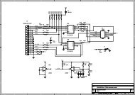
Table 8 - <strong>nRF24LU1</strong> Radio Module Bill of material, common to both versions, except where noted<br />
Revision 1.0 Page 36 of 36


