Create successful ePaper yourself
Turn your PDF publications into a flip-book with our unique Google optimized e-Paper software.
<strong>nRF24LU1</strong> <strong>Development</strong> <strong>Kit</strong> <strong>User</strong> <strong>Guide</strong><br />
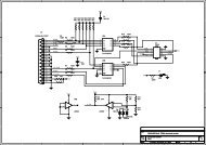
The level shifter is made by resistors and a transistor. Since it is difficult to use a level shifter in a bidirectional<br />
data line, the signal is split on the MCU side, so that the input and output are on two<br />
different IO’s. Table 4 shows the connection to the <strong>nRF24LU1</strong>.<br />
PS/2 Signal name <strong>nRF24LU1</strong> Connection<br />
Data in P0.0<br />
Data out P0.1<br />
Clock in P0.3<br />
Clock out P0.2<br />
Table 4 - PS/2 connection<br />
Revision 1.0 Page 29 of 36


