Pneumatic Fixtured Drills - Douwes International B.V.
Pneumatic Fixtured Drills - Douwes International B.V. Pneumatic Fixtured Drills - Douwes International B.V.
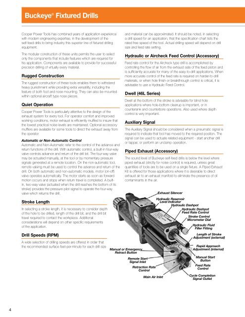
Buckeye ® Fixtured Drills Cooper Power Tools has combined years of application experience with modern engineering expertise, in the development of the self-feed drills to bring industry this superior line of fixtured drilling equipment. The modular construction of these units permits the user to select only the components that include features which are required for his application. Components are available to provide for successful precision drilling of virtually every material. Rugged Construction The rugged construction of these tools enables them to withstand heavy punishment while providing extra versatility, including the feature of both foot and nose mounting. They can also be mounted within optional aircraft type nose pieces. Quiet Operation Cooper Power Tools is particularly attentive to the design of the exhaust system for every tool. For operator comfort and improved working conditions, motor exhaust is efficiently muffled to insure that the lowest practical noise levels are maintained. Optional accessory mufflers are available for some tools to direct the exhaust away from the operator. Automatic or Non-Automatic Control Automatic and Non-Automatic refer to the control of the advance and return functions of the drill. With automatic control, a built-in four-way valve controls advance and return of the drill bit. The four-way valve may be actuated manually, at the tool or by momentary pressure signals generated at a remote location. On the non-automatic tool, remote valving must be used to control the advance and return of the drill. On both automatic and non-automatic models, motor (on-off) valve operates automatically. The motor starts as soon as forward motion occurs and stops when return travel is completed. A builtin, two-way valve (actuated when the drill reaches the bottom of its stroke) provides the pressure pilot signal to operate the four-way valve which returns the drill. Stroke Length In selecting a stroke length, it is necessary to consider depth of the hole to be drilled, length of the drill bit, and the drill bit travel required to contact the workpiece. Additional considerations will depend on other specific requirements of the application. Drill Speeds (RPM) A wide selection of drilling speeds are offered in order that the recommended surface feet-per-minute for each drill size and material can be approximated. It should be noted, in selecting a drill speed for an application, that the specification chart lists the rated free speed of the tool. Actual drilling speed will depend on drill size and feed rate setting. Hydraulic or Aircheck Feed Control (Accessory) Feed rate control for the Aircheck type drill is accomplished by controlling the flow of air from the exhaust side of the feed piston and is sufficiently accurate for many of the easy-to-drill applications. When more accurate control of the feed rate is required on harder-to-drill materials, or when hole finish or breakthrough control is critical, it is advisable to use a Hydraulic Feed Control. Dwell (46L Series) Dwell at the bottom of the stroke is advisable for blind hole applications where hole-bottom cleanup is important, or in countersink and counterbore operations. Also used where depth control is very important. Auxiliary Signal The Auxiliary Signal should be considered when a pneumatic signal is required to indicate that tool has moved to the required position. The signal can be used to actuate related equipment - start another drill or tapper, or perform an unclamp operation. Piped Exhaust (Accessory) The sound level of Buckeye self-feed drills is below the level where piped exhaust (strictly for noise control) is required, unless great quantities of tools are to be used on a single fixture. A Piped Exhaust Kit is offered for those applications where it is desirable to direct exhaust air to an exhaust manifold to eliminate the presence of oil contaminants in the air. Manual or Emergency Retract Button Remote Start Signal Inlet Retraction Rate Control Main Air Inlet Exhaust Silencer Hydraulic Reservoir Level Indicator Hydraulic Dashpot Hydraulic Dashpot Feed Rate Control Stroke Control Micrometer Dial Hydraulic Fluid Filler Fitting Length of Stroke Adjustment (external) Rapid Approach Adjustment (internal) Manual Start Button Feed Rate Control Cycle Completion Signal Outlet
Drill & Horsepower Data Drill Speed Guide The table below is offered to assist in the selection of the proper spindle speeds to suit the most common drilling applications. This data is intended as a guide only, inasmuch as the operating conditions may vary widely. Keep in mind that high speed air drills deliver maximum horsepower when they are loaded to a point where the listed free speed is reduced about one-half. It may also be necessary to deviate from these speeds in order to insure satisfactory cutting tool life. Material Surface Ft. per Min. Suggested Revolutions per Minute Required for Proper Surface Feet per Minute Drill Size 1/16 1/8 3/16 1/4 5/16 3/8 7/16 1/2 9/16 5/8 11/16 3/4 Stainless Steel 30-40 2100 1100 700 550 400 350 300 250 230 200 190 175 Forged Steel 40-50 2700 1350 900 675 550 450 400 350 300 275 250 225 High Nickel Steel or Monel 40-50 2700 1350 900 675 550 450 400 350 300 275 250 225 Titanium Alloy Sheet 50-60 3300 1650 1100 850 650 550 450 400 375 325 300 275 High Carbon Steel 70-80 4600 2300 1500 1100 900 750 650 575 500 450 400 375 Malleable Iron 80-90 5200 2600 1700 1300 1000 850 750 650 575 525 475 425 Mild Steel 80-110 6100 3000 2000 1500 1200 1000 900 750 675 600 550 500 Mild Steel Sheet 80-110 6700 3350 2250 1650 1350 1100 950 850 750 675 600 550 Medium Hard Cast Iron 70-100 5200 2600 1700 1300 1000 850 750 650 575 525 475 425 Soft Cast Iron 100-150 7600 3800 2500 1900 1500 1100 950 850 750 700 700 650 Plastic and Bakelite 100-150 7600 3800 2500 2000 1500 1250 1100 950 850 750 700 650 High Tensile Bronze 70-150 6700 3300 2250 1650 1350 1100 950 850 750 675 600 550 Commercial Brass or Bronze 200-300 15000 7600 5100 3800 3000 2500 2200 2000 1700 1500 1400 1300 Aluminum 200-300 15000 7600 5100 3800 3000 2500 2200 2000 1700 1500 1400 1300 Aluminum Sheet 200-300 18000 9100 6100 4500 3500 3000 2500 2250 2000 1700 1500 1400 Magnesium 250-400 18500 9200 6100 4600 3600 3100 2600 2250 2000 1900 1800 1650 Wood 300-400 18500 9200 6100 4500 3600 3000 2600 2250 2100 2000 1900 1800 NOTE: This table is for use with High Speed Steel drills only. Carbon Steel drills should run at 40-50% of listed speeds. Drill Horsepower & Thrust Chart Material Specification For Drill Size 1/16 3/32 1/8 3/16 1/4 5/16 3/8 7/16 1/2 Brass R.P.M. 4000 4000 4000 3000 2200 1800 1500 1300 1100 Feed”/Rev. .0004 .0005 .0008 .0012 .0017 .0021 .0025 .003 .0035 H.P. .010 .012 .022 .047 .100 .150 .200 .250 .300 Thrust (lbs.) 3 6 10 20 35 50 70 90 100 Aluminum R.P.M. 4000 4000 4000 4000 3000 2500 2000 1700 1500 Feed”/Rev. .0005 .0007 .0010 .0015 .0020 .0025 .0030 .0035 .0040 H.P. .010 .020 .040 .080 .140 .220 .300 .375 .450 Thrust (lbs.) 2 3 6 12 20 40 60 80 100 Cast Iron R.P.M. 4000 2850 2100 1400 1000 850 700 600 525 Feed”/Rev. .0005 .0007 .0010 .0015 .0020 .0022 .0027 .0030 .0035 H.P. .010 .020 .035 .060 .100 .125 .175 .210 .250 Thrust (lbs.) 6 12 30 45 90 100 140 180 225 B1112 Mild Steel R.P.M. 3600 2400 1800 1200 900 750 600 525 450 Feed”/Rev. .0005 .0007 .0010 .0015 .0022 .0027 .0032 .0037 .0045 H.P. .015 .025 .040 .075 .125 .175 .250 .300 .365 Thrust (lbs.) 8 12 25 50 85 130 175 250 310 1045 Steel R.P.M. 3600 2400 1800 1200 900 750 600 525 450 Feed”/Rev. .0005 .0007 .0010 .0015 .0022 .0027 .0032 .0037 .0045 H.P. .03 .05 .09 .15 .22 .25 .40 .60 .65 Thrust (lbs.) 12 20 25 75 140 200 280 350 450
- Page 1 and 2: SP-105EN 0308 3.5M ® Buckeye Pneum
- Page 3 and 4: ISO 9001 Cooper Power Tools Divisio
- Page 5: Cooper Industries, Cooper Power Too
- Page 9 and 10: 21L Series Mounting Dimensions Desi
- Page 11 and 12: 31L Series Mounting Dimensions Desi
- Page 13 and 14: 42L Series Mounting Dimensions Desi
- Page 15 and 16: 46L Series Mounting Dimensions Desi
- Page 17 and 18: 21LH Series Mounting Dimensions Des
- Page 19 and 20: Mounting Dimensions Designer’s fu
- Page 21 and 22: 21LD Series Mounting Dimensions Des
- Page 23 and 24: 42LD Series Mounting Dimensions Des
- Page 25 and 26: Multiple Spindle Drill Head Collets
- Page 27 and 28: Self-Feed Tools Accessories Hydraul
- Page 29 and 30: Self-Feed Tools Accessories Industr
- Page 31 and 32: Fixture Post Mounting Components 11
- Page 33 and 34: Self-Feed Tools Accessories Aircraf
- Page 35 and 36: Self-Feed Air Tool Circuitry Multip
- Page 37 and 38: Self-Feed Air Tool Circuitry Multip
- Page 39 and 40: Self-Feed Air Tool Circuitry Self-F
- Page 41 and 42: Notes 39
- Page 44 and 45: Sales & Service Centers Note: All l
- Page 46 and 47: Order Catalogs & Literature On-Line
Buckeye ® <strong>Fixtured</strong> <strong>Drills</strong><br />
Cooper Power Tools has combined years of application experience<br />
with modern engineering expertise, in the development of the<br />
self-feed drills to bring industry this superior line of fixtured drilling<br />
equipment.<br />
The modular construction of these units permits the user to select<br />
only the components that include features which are required for<br />
his application. Components are available to provide for successful<br />
precision drilling of virtually every material.<br />
Rugged Construction<br />
The rugged construction of these tools enables them to withstand<br />
heavy punishment while providing extra versatility, including the<br />
feature of both foot and nose mounting. They can also be mounted<br />
within optional aircraft type nose pieces.<br />
Quiet Operation<br />
Cooper Power Tools is particularly attentive to the design of the<br />
exhaust system for every tool. For operator comfort and improved<br />
working conditions, motor exhaust is efficiently muffled to insure that<br />
the lowest practical noise levels are maintained. Optional accessory<br />
mufflers are available for some tools to direct the exhaust away from<br />
the operator.<br />
Automatic or Non-Automatic Control<br />
Automatic and Non-Automatic refer to the control of the advance and<br />
return functions of the drill. With automatic control, a built-in four-way<br />
valve controls advance and return of the drill bit. The four-way valve<br />
may be actuated manually, at the tool or by momentary pressure<br />
signals generated at a remote location. On the non-automatic tool,<br />
remote valving must be used to control the advance and return of the<br />
drill. On both automatic and non-automatic models, motor (on-off)<br />
valve operates automatically. The motor starts as soon as forward<br />
motion occurs and stops when return travel is completed. A builtin,<br />
two-way valve (actuated when the drill reaches the bottom of its<br />
stroke) provides the pressure pilot signal to operate the four-way<br />
valve which returns the drill.<br />
Stroke Length<br />
In selecting a stroke length, it is necessary to consider depth<br />
of the hole to be drilled, length of the drill bit, and the drill bit<br />
travel required to contact the workpiece. Additional<br />
considerations will depend on other specific requirements<br />
of the application.<br />
Drill Speeds (RPM)<br />
A wide selection of drilling speeds are offered in order that<br />
the recommended surface feet-per-minute for each drill size<br />
and material can be approximated. It should be noted, in selecting<br />
a drill speed for an application, that the specification chart lists the<br />
rated free speed of the tool. Actual drilling speed will depend on drill<br />
size and feed rate setting.<br />
Hydraulic or Aircheck Feed Control (Accessory)<br />
Feed rate control for the Aircheck type drill is accomplished by<br />
controlling the flow of air from the exhaust side of the feed piston and<br />
is sufficiently accurate for many of the easy-to-drill applications. When<br />
more accurate control of the feed rate is required on harder-to-drill<br />
materials, or when hole finish or breakthrough control is critical, it is<br />
advisable to use a Hydraulic Feed Control.<br />
Dwell (46L Series)<br />
Dwell at the bottom of the stroke is advisable for blind hole<br />
applications where hole-bottom cleanup is important, or in<br />
countersink and counterbore operations. Also used where depth<br />
control is very important.<br />
Auxiliary Signal<br />
The Auxiliary Signal should be considered when a pneumatic signal is<br />
required to indicate that tool has moved to the required position. The<br />
signal can be used to actuate related equipment - start another drill<br />
or tapper, or perform an unclamp operation.<br />
Piped Exhaust (Accessory)<br />
The sound level of Buckeye self-feed drills is below the level where<br />
piped exhaust (strictly for noise control) is required, unless great<br />
quantities of tools are to be used on a single fixture. A Piped Exhaust<br />
Kit is offered for those applications where it is desirable to direct<br />
exhaust air to an exhaust manifold to eliminate the presence of oil<br />
contaminants in the air.<br />
Manual or Emergency<br />
Retract Button<br />
Remote Start<br />
Signal Inlet<br />
Retraction Rate<br />
Control<br />
Main Air Inlet<br />
Exhaust Silencer<br />
Hydraulic Reservoir<br />
Level Indicator<br />
Hydraulic Dashpot<br />
Hydraulic Dashpot<br />
Feed Rate Control<br />
Stroke Control<br />
Micrometer Dial<br />
Hydraulic Fluid<br />
Filler Fitting<br />
Length of Stroke<br />
Adjustment (external)<br />
Rapid Approach<br />
Adjustment (internal)<br />
Manual Start<br />
Button<br />
Feed Rate<br />
Control<br />
Cycle Completion<br />
Signal Outlet


