Pneumatic Fixtured Drills - Douwes International B.V.
Pneumatic Fixtured Drills - Douwes International B.V.
Pneumatic Fixtured Drills - Douwes International B.V.

Create successful ePaper yourself
Turn your PDF publications into a flip-book with our unique Google optimized e-Paper software.
SP-105EN 0308 3.5M<br />
®<br />
Buckeye<br />
<strong>Pneumatic</strong> <strong>Fixtured</strong> <strong>Drills</strong>
Table of Contents<br />
ISO Quality System Certification. . . . . . . . . . . . . . . . . . . . . . . . . . . . . . . . . . . . . . 1<br />
Model Number Index. . . . . . . . . . . . . . . . . . . . . . . . . . . . . . . . . . . . . . . . . . . . . . . 2<br />
Warranty. . . . . . . . . . . . . . . . . . . . . . . . . . . . . . . . . . . . . . . . . . . . . . . . . . . . . . . . . 3<br />
Lubrication Products . . . . . . . . . . . . . . . . . . . . . . . . . . . . . . . . . . . . . . . . . . . . . . . 3<br />
Buckeye <strong>Fixtured</strong> <strong>Drills</strong> Introduction. . . . . . . . . . . . . . . . . . . . . . . . . . . . . . . . . . . 4<br />
Drill and Horsepower Data Guide. . . . . . . . . . . . . . . . . . . . . . . . . . . . . . . . . . . . . 5<br />
Self–Feed <strong>Drills</strong> . . . . . . . . . . . . . . . . . . . . . . . . . . . . . . . . . . . . . . . . . . . . . . . . . . 6-13<br />
21LD Series . . . . . . . . . . . . . . . . . . . . . . . . . . . . . . . . . . . . . . . . . . . . . . . . . 6-7<br />
31LD Series . . . . . . . . . . . . . . . . . . . . . . . . . . . . . . . . . . . . . . . . . . . . . . . . . 8-9<br />
42LD Series . . . . . . . . . . . . . . . . . . . . . . . . . . . . . . . . . . . . . . . . . . . . . . . . . 10-11<br />
46LD Series . . . . . . . . . . . . . . . . . . . . . . . . . . . . . . . . . . . . . . . . . . . . . . . . . 12-13<br />
Self–Feed Offset <strong>Drills</strong>. . . . . . . . . . . . . . . . . . . . . . . . . . . . . . . . . . . . . . . . . . . . . 14-15<br />
21LDH Series. . . . . . . . . . . . . . . . . . . . . . . . . . . . . . . . . . . . . . . . . . . . . . . . 14-15<br />
31LDH Series. . . . . . . . . . . . . . . . . . . . . . . . . . . . . . . . . . . . . . . . . . . . . . . . 14-15<br />
Self–Feed Tappers . . . . . . . . . . . . . . . . . . . . . . . . . . . . . . . . . . . . . . . . . . . . . . . . 16-17<br />
31LD, & 46LD Series. . . . . . . . . . . . . . . . . . . . . . . . . . . . . . . . . . . . . . . . . . 16-17<br />
Self–Feed Multiple Spindle Head <strong>Drills</strong>. . . . . . . . . . . . . . . . . . . . . . . . . . . . . . . 18-21<br />
21LD Series . . . . . . . . . . . . . . . . . . . . . . . . . . . . . . . . . . . . . . . . . . . . . . . . . 18-19<br />
31LD Series . . . . . . . . . . . . . . . . . . . . . . . . . . . . . . . . . . . . . . . . . . . . . . . . . 18-19<br />
42LD Series . . . . . . . . . . . . . . . . . . . . . . . . . . . . . . . . . . . . . . . . . . . . . . . . . 20-21<br />
46LD Series . . . . . . . . . . . . . . . . . . . . . . . . . . . . . . . . . . . . . . . . . . . . . . . . . 20-21<br />
Multiple Spindle Head. . . . . . . . . . . . . . . . . . . . . . . . . . . . . . . . . . . . . . . . . 22<br />
Multiple Spindle Head Collets . . . . . . . . . . . . . . . . . . . . . . . . . . . . . . . . . . 23-24<br />
Self–Feed Drill Accessories . . . . . . . . . . . . . . . . . . . . . . . . . . . . . . . . . . . . . . . . 25-31<br />
Hydraulic & Outboard Dashpots. . . . . . . . . . . . . . . . . . . . . . . . . . . . . . . . . 25<br />
Exhaust Deflectors . . . . . . . . . . . . . . . . . . . . . . . . . . . . . . . . . . . . . . . . . . . 25<br />
Chuck Body Assemblies. . . . . . . . . . . . . . . . . . . . . . . . . . . . . . . . . . . . . . . 26<br />
Collets . . . . . . . . . . . . . . . . . . . . . . . . . . . . . . . . . . . . . . . . . . . . . . . . . . . . . 26<br />
Industrial 3–Jaw Chucks. . . . . . . . . . . . . . . . . . . . . . . . . . . . . . . . . . . . . . . 27<br />
1022162 Remote Start Valve . . . . . . . . . . . . . . . . . . . . . . . . . . . . . . . . . . . 27<br />
Fixture Post Mounting Components . . . . . . . . . . . . . . . . . . . . . . . . . . . . . 28-29<br />
L–Bracket Mount. . . . . . . . . . . . . . . . . . . . . . . . . . . . . . . . . . . . . . . . . . . . . 30<br />
Morse Taper Adapter. . . . . . . . . . . . . . . . . . . . . . . . . . . . . . . . . . . . . . . . . . 30<br />
Aircraft Nose Mount & Adapters. . . . . . . . . . . . . . . . . . . . . . . . . . . . . . . . . 31<br />
Self–Feed Air Tool Circuitry. . . . . . . . . . . . . . . . . . . . . . . . . . . . . . . . . . . . . 32-37<br />
General Accessories. . . . . . . . . . . . . . . . . . . . . . . . . . . . . . . . . . . . . . . . . . . . . . 38-39<br />
Training. . . . . . . . . . . . . . . . . . . . . . . . . . . . . . . . . . . . . . . . . . . . . . . . . . . . . . . . . . 40-41<br />
Sales & Service Centers . . . . . . . . . . . . . . . . . . . . . . . . . . . . . . . . . . . . . . . . . . . . 42<br />
Cooper Power Tools On The Web . . . . . . . . . . . . . . . . . . . . . . . . . . . . . . . . . . . . 43<br />
Catalogs. . . . . . . . . . . . . . . . . . . . . . . . . . . . . . . . . . . . . . . . . . . . . . . . . . . . . . . . . 44
ISO 9001<br />
Cooper Power Tools Division has attained ISO 9001 Quality System<br />
Certification for seven of our facilities. The driving force behind the<br />
implementation of the Quality System is the commitment “to provide<br />
our customers with the best value delivered by offering only<br />
products and services that meet or exceed their expectations”.<br />
Lexington, South Carolina<br />
Dayton, Ohio<br />
Hicksville, Ohio<br />
Springfield, Ohio<br />
Braunschweig, Germany Westhausen, Germany Ozoir-la-Ferrière, France
Table Model of Contents Number Index<br />
Model No. Description<br />
Page<br />
Model No. Description<br />
Page<br />
21LD-702<br />
21LD-703<br />
21LD-772<br />
21LD-773<br />
21LD-800<br />
Multiple Spindle.........................................................18<br />
Multiple Spindle.........................................................18<br />
Multiple Spindle.........................................................18<br />
Multiple Spindle.........................................................18<br />
Self-Feed Drill..............................................................6<br />
31L-816 Tapper........................................................................16<br />
31L-817 Tapper........................................................................16<br />
31LDH-803 Offset Head................................................................18<br />
31LDH-806 Offset Head................................................................18<br />
31LDH-807 Offset Head................................................................18<br />
21LD-801<br />
Self-Feed Drill..............................................................6<br />
42LD-801<br />
Self-Feed Drill............................................................10<br />
21LD-802<br />
Self-Feed Drill..............................................................6<br />
42LD-801<br />
Multiple Spindle.........................................................20<br />
21LD-803<br />
Self-Feed Drill..............................................................6<br />
42LD-802<br />
Self-Feed Drill............................................................10<br />
21L-805 Self-Feed Drill..............................................................6<br />
21L-815 Tapper........................................................................16<br />
42LD-802<br />
42LD-803<br />
Multiple Spindle.........................................................20<br />
Self-Feed Drill............................................................10<br />
21LD-870<br />
Self-Feed Drill..............................................................6<br />
42LD-803<br />
Multiple Spindle.........................................................20<br />
21LD-871<br />
Self-Feed Drill..............................................................6<br />
42LD-805<br />
Self-Feed Drill............................................................10<br />
21LD-872<br />
Self-Feed Drill..............................................................6<br />
42LD-805<br />
Multiple Spindle.........................................................20<br />
21LD-873<br />
Self-Feed Drill..............................................................6<br />
46LD-801<br />
Self-Feed Drill............................................................12<br />
21LD-875<br />
Self-Feed Drill..............................................................6<br />
46LD-802<br />
Self-Feed Drill............................................................12<br />
21LDH-801 Offset Head................................................................14<br />
21LDH-802 Offset Head................................................................14<br />
21LDH-803 Offset Head................................................................14<br />
21LDH-805 Offset Head................................................................14<br />
46LD-802<br />
46LD-803<br />
46LD-803<br />
46LD-805<br />
Multiple Spindle.........................................................20<br />
Self-Feed Drill............................................................12<br />
Multiple Spindle.........................................................20<br />
Self-Feed Drill............................................................12<br />
31LD-800<br />
Self-Feed Drill..............................................................8<br />
46LD-805<br />
Multiple Spindle.........................................................20<br />
31LD-801<br />
Self-Feed Drill..............................................................8<br />
46LD-806<br />
Self-Feed Drill............................................................12<br />
31LD-801<br />
Multiple Spindle.........................................................18<br />
46LD-807<br />
Self-Feed Drill............................................................12<br />
31LD-802<br />
Self-Feed Drill..............................................................8<br />
46LD-808<br />
Self-Feed Drill............................................................12<br />
31LD-802<br />
31LD-803<br />
31LD-805<br />
31LD-805<br />
Multiple Spindle.........................................................18<br />
Self-Feed Drill..............................................................8<br />
Multiple Spindle.........................................................18<br />
Self-Feed Drill..............................................................8<br />
46L-815 Tapper........................................................................16<br />
46L-816 Tapper........................................................................16<br />
46L-817 Tapper........................................................................16<br />
46L-818 Tapper........................................................................16<br />
31LD-806<br />
Self-Feed Drill..............................................................8<br />
42LD-806<br />
Self-Feed Drill............................................................10<br />
31LD-807<br />
Self-Feed Drill..............................................................8<br />
42LD-807<br />
Self-Feed Drill............................................................10
Cooper Industries, Cooper Power Tools Division<br />
Warranty<br />
Cooper warrants products and parts sold by it,<br />
insofar as they are of its own manufacture, against<br />
defects of material and workmanship, under normal<br />
use and service in accordance with its written<br />
instructions, recommendations, and ratings for<br />
installation, operation, maintenance, and service of<br />
products, for a period of ONE YEAR FROM THE<br />
DATE OF INITIAL USE, BUT IN NO EVENT<br />
SHALL THE WARRANTY EXCEED 24 MONTHS<br />
FROM DATE OF DELIVERY TO DISTRIBUTOR.<br />
Proof of Purchase with shipment date must be<br />
furnished by the user to validate the warranty. This<br />
warranty applies only to products manufactured<br />
by Cooper and specifically excludes products<br />
manufactured by others. Products not manufactured<br />
by Cooper are warranted only to the extent and in<br />
the manner warranted to Cooper by the manufacturer<br />
Lubrication Products<br />
Cooper Power Tools’ products are classified as<br />
non-hazardous manufactured items, defined in the<br />
OSHA 1910.1200 Hazard Communication Standard<br />
as “Articles”. These products, under conditions of<br />
normal use, do not release or cause exposure to a<br />
hazardous chemical.<br />
Under normal conditions of use, lubrication products<br />
sold separately for or used within these tools<br />
should not cause an exposure hazard. Refer to the<br />
Material Safety Data Sheet (M.S.D.S.) for Safety and<br />
Disposal Information. M.S.D.S. sheets are available<br />
upon request from Cooper Power Tools.<br />
Cooper is also aware of, and complies with, the<br />
and then only to the extent Cooper is able to enforce<br />
such warranty. Cooper’s warranty with respect to<br />
products manufactured by it is limited to the repair or<br />
replacement, as Cooper may elect, of any defective<br />
part regarding which the Distributor has given 5 days<br />
written notice from the discovery of such defect.<br />
Installation and transportation costs are not included.<br />
Cooper shall have the option of requiring the<br />
return to it of the defective material, transportation<br />
prepaid, for inspection. No allowance will be made<br />
for repairs without Cooper’s approval. COOPER<br />
MAKES NO OTHER WARRANTY OF ANY KIND<br />
WHATSOEVER, EXPRESSED OR IMPLIED, AND<br />
HEREBY DISCLAIMS ALL WARRANTIES OF<br />
MERCHANTABILITY AND FITNESS FOR A<br />
PARTICULAR PURPOSE.<br />
provisions of section 611 amendments to the Clean<br />
Air Act of 1990. No ozone depleting chemicals have<br />
been used in the manufacture of our products.<br />
If you resell or distribute these products, you have<br />
the responsibility for ensuring that the Material Safety<br />
Data Sheets are provided to the purchaser.<br />
Proper lubrication is essential to the economical<br />
operation of pneumatic and electric tools. Cooper<br />
Power Tools perform better and their life is extended<br />
by using the recommended lubricants. All lubricants<br />
that are listed in the accessory section of this catalog<br />
have undergone extensive testing and are recommended<br />
for use with Cooper Power Tools products.
Buckeye ® <strong>Fixtured</strong> <strong>Drills</strong><br />
Cooper Power Tools has combined years of application experience<br />
with modern engineering expertise, in the development of the<br />
self-feed drills to bring industry this superior line of fixtured drilling<br />
equipment.<br />
The modular construction of these units permits the user to select<br />
only the components that include features which are required for<br />
his application. Components are available to provide for successful<br />
precision drilling of virtually every material.<br />
Rugged Construction<br />
The rugged construction of these tools enables them to withstand<br />
heavy punishment while providing extra versatility, including the<br />
feature of both foot and nose mounting. They can also be mounted<br />
within optional aircraft type nose pieces.<br />
Quiet Operation<br />
Cooper Power Tools is particularly attentive to the design of the<br />
exhaust system for every tool. For operator comfort and improved<br />
working conditions, motor exhaust is efficiently muffled to insure that<br />
the lowest practical noise levels are maintained. Optional accessory<br />
mufflers are available for some tools to direct the exhaust away from<br />
the operator.<br />
Automatic or Non-Automatic Control<br />
Automatic and Non-Automatic refer to the control of the advance and<br />
return functions of the drill. With automatic control, a built-in four-way<br />
valve controls advance and return of the drill bit. The four-way valve<br />
may be actuated manually, at the tool or by momentary pressure<br />
signals generated at a remote location. On the non-automatic tool,<br />
remote valving must be used to control the advance and return of the<br />
drill. On both automatic and non-automatic models, motor (on-off)<br />
valve operates automatically. The motor starts as soon as forward<br />
motion occurs and stops when return travel is completed. A builtin,<br />
two-way valve (actuated when the drill reaches the bottom of its<br />
stroke) provides the pressure pilot signal to operate the four-way<br />
valve which returns the drill.<br />
Stroke Length<br />
In selecting a stroke length, it is necessary to consider depth<br />
of the hole to be drilled, length of the drill bit, and the drill bit<br />
travel required to contact the workpiece. Additional<br />
considerations will depend on other specific requirements<br />
of the application.<br />
Drill Speeds (RPM)<br />
A wide selection of drilling speeds are offered in order that<br />
the recommended surface feet-per-minute for each drill size<br />
and material can be approximated. It should be noted, in selecting<br />
a drill speed for an application, that the specification chart lists the<br />
rated free speed of the tool. Actual drilling speed will depend on drill<br />
size and feed rate setting.<br />
Hydraulic or Aircheck Feed Control (Accessory)<br />
Feed rate control for the Aircheck type drill is accomplished by<br />
controlling the flow of air from the exhaust side of the feed piston and<br />
is sufficiently accurate for many of the easy-to-drill applications. When<br />
more accurate control of the feed rate is required on harder-to-drill<br />
materials, or when hole finish or breakthrough control is critical, it is<br />
advisable to use a Hydraulic Feed Control.<br />
Dwell (46L Series)<br />
Dwell at the bottom of the stroke is advisable for blind hole<br />
applications where hole-bottom cleanup is important, or in<br />
countersink and counterbore operations. Also used where depth<br />
control is very important.<br />
Auxiliary Signal<br />
The Auxiliary Signal should be considered when a pneumatic signal is<br />
required to indicate that tool has moved to the required position. The<br />
signal can be used to actuate related equipment - start another drill<br />
or tapper, or perform an unclamp operation.<br />
Piped Exhaust (Accessory)<br />
The sound level of Buckeye self-feed drills is below the level where<br />
piped exhaust (strictly for noise control) is required, unless great<br />
quantities of tools are to be used on a single fixture. A Piped Exhaust<br />
Kit is offered for those applications where it is desirable to direct<br />
exhaust air to an exhaust manifold to eliminate the presence of oil<br />
contaminants in the air.<br />
Manual or Emergency<br />
Retract Button<br />
Remote Start<br />
Signal Inlet<br />
Retraction Rate<br />
Control<br />
Main Air Inlet<br />
Exhaust Silencer<br />
Hydraulic Reservoir<br />
Level Indicator<br />
Hydraulic Dashpot<br />
Hydraulic Dashpot<br />
Feed Rate Control<br />
Stroke Control<br />
Micrometer Dial<br />
Hydraulic Fluid<br />
Filler Fitting<br />
Length of Stroke<br />
Adjustment (external)<br />
Rapid Approach<br />
Adjustment (internal)<br />
Manual Start<br />
Button<br />
Feed Rate<br />
Control<br />
Cycle Completion<br />
Signal Outlet
Drill & Horsepower Data<br />
Drill Speed Guide<br />
The table below is offered to assist in the selection of the proper<br />
spindle speeds to suit the most common drilling applications.<br />
This data is intended as a guide only, inasmuch as the operating<br />
conditions may vary widely.<br />
Keep in mind that high speed air drills deliver maximum horsepower<br />
when they are loaded to a point where the listed free speed is<br />
reduced about one-half. It may also be necessary to deviate from<br />
these speeds in order to insure satisfactory cutting tool life.<br />
Material<br />
Surface Ft.<br />
per Min.<br />
Suggested Revolutions per Minute Required for Proper Surface Feet per Minute<br />
Drill Size<br />
1/16 1/8 3/16 1/4 5/16 3/8 7/16 1/2 9/16 5/8 11/16 3/4<br />
Stainless Steel 30-40 2100 1100 700 550 400 350 300 250 230 200 190 175<br />
Forged Steel 40-50 2700 1350 900 675 550 450 400 350 300 275 250 225<br />
High Nickel Steel or Monel 40-50 2700 1350 900 675 550 450 400 350 300 275 250 225<br />
Titanium Alloy Sheet 50-60 3300 1650 1100 850 650 550 450 400 375 325 300 275<br />
High Carbon Steel 70-80 4600 2300 1500 1100 900 750 650 575 500 450 400 375<br />
Malleable Iron 80-90 5200 2600 1700 1300 1000 850 750 650 575 525 475 425<br />
Mild Steel 80-110 6100 3000 2000 1500 1200 1000 900 750 675 600 550 500<br />
Mild Steel Sheet 80-110 6700 3350 2250 1650 1350 1100 950 850 750 675 600 550<br />
Medium Hard Cast Iron 70-100 5200 2600 1700 1300 1000 850 750 650 575 525 475 425<br />
Soft Cast Iron 100-150 7600 3800 2500 1900 1500 1100 950 850 750 700 700 650<br />
Plastic and Bakelite 100-150 7600 3800 2500 2000 1500 1250 1100 950 850 750 700 650<br />
High Tensile Bronze 70-150 6700 3300 2250 1650 1350 1100 950 850 750 675 600 550<br />
Commercial Brass or Bronze 200-300 15000 7600 5100 3800 3000 2500 2200 2000 1700 1500 1400 1300<br />
Aluminum 200-300 15000 7600 5100 3800 3000 2500 2200 2000 1700 1500 1400 1300<br />
Aluminum Sheet 200-300 18000 9100 6100 4500 3500 3000 2500 2250 2000 1700 1500 1400<br />
Magnesium 250-400 18500 9200 6100 4600 3600 3100 2600 2250 2000 1900 1800 1650<br />
Wood 300-400 18500 9200 6100 4500 3600 3000 2600 2250 2100 2000 1900 1800<br />
NOTE: This table is for use with High Speed Steel drills only. Carbon Steel drills should run at 40-50% of listed speeds.<br />
Drill Horsepower & Thrust Chart<br />
Material<br />
Specification<br />
For<br />
Drill Size<br />
1/16 3/32 1/8 3/16 1/4 5/16 3/8 7/16 1/2<br />
Brass R.P.M. 4000 4000 4000 3000 2200 1800 1500 1300 1100<br />
Feed”/Rev. .0004 .0005 .0008 .0012 .0017 .0021 .0025 .003 .0035<br />
H.P. .010 .012 .022 .047 .100 .150 .200 .250 .300<br />
Thrust (lbs.) 3 6 10 20 35 50 70 90 100<br />
Aluminum R.P.M. 4000 4000 4000 4000 3000 2500 2000 1700 1500<br />
Feed”/Rev. .0005 .0007 .0010 .0015 .0020 .0025 .0030 .0035 .0040<br />
H.P. .010 .020 .040 .080 .140 .220 .300 .375 .450<br />
Thrust (lbs.) 2 3 6 12 20 40 60 80 100<br />
Cast Iron R.P.M. 4000 2850 2100 1400 1000 850 700 600 525<br />
Feed”/Rev. .0005 .0007 .0010 .0015 .0020 .0022 .0027 .0030 .0035<br />
H.P. .010 .020 .035 .060 .100 .125 .175 .210 .250<br />
Thrust (lbs.) 6 12 30 45 90 100 140 180 225<br />
B1112 Mild Steel R.P.M. 3600 2400 1800 1200 900 750 600 525 450<br />
Feed”/Rev. .0005 .0007 .0010 .0015 .0022 .0027 .0032 .0037 .0045<br />
H.P. .015 .025 .040 .075 .125 .175 .250 .300 .365<br />
Thrust (lbs.) 8 12 25 50 85 130 175 250 310<br />
1045 Steel R.P.M. 3600 2400 1800 1200 900 750 600 525 450<br />
Feed”/Rev. .0005 .0007 .0010 .0015 .0022 .0027 .0032 .0037 .0045<br />
H.P. .03 .05 .09 .15 .22 .25 .40 .60 .65<br />
Thrust (lbs.) 12 20 25 75 140 200 280 350 450
Self-Feed <strong>Drills</strong><br />
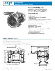
21LD-800 Series<br />
■ .4 Horsepower<br />
■ 130 lbs. Thrust (578 N) @ 90 PSI<br />
■ 1-1/4” (32mm) & 2” (51mm) Stroke<br />
■ Cycle completion signal<br />
21LD-870 Series Automatic<br />
■ Internal rear-head valves<br />
■ Automatic retract<br />
■ Manual start & retract<br />
■ Remote start<br />
■ 1” (25mm) stroke hydraulic dashpot standard<br />
Models<br />
Nominal Drilling Capacity<br />
Free<br />
Thrust @ 90PSI<br />
Standard Chuck<br />
Stroke Length<br />
Speed<br />
Capacity<br />
RPM Mild Steel Aluminum Wood<br />
1 1/4” (32mm) 2” (51mm)<br />
in. mm in. mm in. mm lb. N in. mm<br />
Spindle<br />
Automatic<br />
21LD-870 21LD-800 22000 – – 3/32 2.4 – – 130 578 5/32 4.0 #0 JT<br />
21LD-871 21LD-801 4750 1/8 3.2 3/16 4.8 3/16 4.8 130 578 1/4 6.4 3/8”-24<br />
21LD-872 21LD-802 3500 5/32 4.0 7/32 5.6 1/4 6.4 130 578 1/4 6.4 3/8”-24<br />
21LD-873 21LD-803 2800 3/16 4.8 1/4 6.4 5/16 7.9 130 578 1/4 6.4 3/8”-24<br />
21LD-875 21LD-805 900 1/4 6.4 1/4 6.4 1/2 12.7 130 578 1/4 6.4 3/8”-24<br />
Specifications:<br />
Recommended Air Pressure: 90 PSI (6.2 bar)<br />
Air Inlet Size:<br />
1/4” N.P.T.<br />
CFM Rating:<br />
14 @ Free Speed<br />
Remote Control Ports:<br />
1/8” N.P.T.<br />
Recommended Hose Size: 3/8” (9.5 mm) I.D.<br />
Offset (side-to-center):<br />
7/8” (22.2 mm)<br />
Tool Weight (maximum):<br />
5.6 lbs. (2.5 kg)<br />
Optional Chucks: page 26<br />
Standard Equipment: The above models are<br />
supplied standard with a 1” stroke hydraulic<br />
dashpot, 1024850. See page 25 for more<br />
information.<br />
Extra Cost Accessories:<br />
Optional Outboard Dashpots: page 25<br />
L - Bracket: 1021862<br />
Aircraft Noses: page 31<br />
Collet Type Chucks: page 26<br />
Various 3-Jawed Chucks: page 27
21L Series<br />
Mounting Dimensions<br />
Designer’s full scale dimensional layouts<br />
available online at www.cooperpowertools.com.<br />
Overall Length<br />
Free Speed of Tool (RPM)<br />
Stroke Length<br />
“A”<br />
“B”<br />
1 1/4” (32mm) 2” (51mm)<br />
in. mm in. mm in. mm in. mm<br />
22000 11.50 292 12.13 308 1.92 49 0.62 16<br />
4750 11.69 297 12.44 316 2.19 56 0.62 16<br />
3500 11.69 297 12.44 316 2.19 56 0.62 16<br />
2800 11.69 297 12.44 316 2.19 56 0.62 16<br />
900 12.75 324 13.50 343 3.28 83 1.71 43
Self-Feed <strong>Drills</strong><br />
31LD-800 Series Automatic<br />
■ .6 Horsepower<br />
■ 200 lbs. Thrust (889 N) @ 90 PSI<br />
■ 3” (76mm) Stroke<br />
■ Cycle completion signal<br />
■ Internal rear-head valves<br />
■ Automatic retract<br />
■ Manual start & retract<br />
■ Remote start<br />
■ 2” (51mm) stroke hydraulic dashpot standard<br />
Models<br />
Nominal Drilling Capacity<br />
Free<br />
Thrust @ 90PSI<br />
Standard Chuck<br />
Stroke Length<br />
Speed<br />
Capacity<br />
RPM Mild Steel Aluminum Wood<br />
3” (76mm)<br />
in. mm in. mm in. mm lb. N in. mm<br />
Spindle<br />
Automatic<br />
31LD-800 20000 – – – – – – – – – – –<br />
31LD-801 5000 1/8 3.2 3/16 4.8 1/4 6.4 200 889 3/8 9.5 3/8”-24<br />
31LD-802 3000 3/16 4.8 5/16 7.9 3/8 9.5 200 889 3/8 9.5 3/8”-24<br />
31LD-803 1850 3/16 4.8 3/8 9.5 1/2 12.7 200 889 3/8 9.5 3/8”-24<br />
31LD-805 1100 5/16 7.9 3/8 9.5 5/8 15.9 200 889 3/8 9.5 3/8”-24<br />
31LD-806 750 3/8 9.5 3/8 9.5 7/8 22.2 200 889 3/8 9.5 3/8”-24<br />
31LD-807 450 3/8 9.5 3/8 9.5 1 25.4 200 889 3/8 9.5 3/8”-24<br />
Specifications:<br />
Recommended Air Pressure: 90 PSI (6.2 bar)<br />
Air Inlet Size:<br />
1/4” N.P.T.<br />
CFM Rating:<br />
@ Free Speed<br />
Remote Control Ports:<br />
1/8” N.P.T.<br />
Recommended Hose Size: 3/8” (9.5 mm) I.D.<br />
Offset (side-to-center):<br />
1” (25.4 mm)<br />
Tool Weight (maximum):<br />
9.7 lbs. (4.4 kg)<br />
Optional Chucks: page 26<br />
Standard Equipment: The above models are<br />
supplied standard with 2” stroke hydraulic<br />
dashpot, 1024852. See page 25 for more<br />
information.<br />
Extra Cost Accessories:<br />
Optional Outboard Dashpots: page 25<br />
L - Bracket: 1023793<br />
Aircraft Noses: page 31<br />
Collet Type Chucks: page 26<br />
Various 3-Jawed Chucks: page 27
31L Series<br />
Mounting Dimensions<br />
Designer’s full scale dimensional layouts<br />
available online at www.cooperpowertools.com.
Self-Feed <strong>Drills</strong><br />
42LD-800 Series<br />
■ .9 Horsepower<br />
■ 250 lbs. Thrust (1111 N) @ 90 PSI<br />
■ 3” (76mm) Stroke<br />
■ Cycle completion signal<br />
■ Internal rear-head valves<br />
■ Automatic retract<br />
■ Manual start & retract<br />
■ Remote start<br />
■ 2” (51mm) stroke hydraulic dashpot standard<br />
Models<br />
Nominal Drilling Capacity<br />
Free<br />
Thrust @ 90PSI<br />
Standard Chuck<br />
Stroke Length<br />
Speed<br />
Capacity<br />
RPM Mild Steel Aluminum Wood<br />
3” (76mm)<br />
in. mm in. mm in. mm lb. N in. mm<br />
Spindle<br />
Automatic<br />
42LD-808 6000 1/8 3.2 1/8 3.2 3/16 4.8 250 1111 3/8 9.5 3/8”-24<br />
42LD-801 5000 3/16 4.8 1/4 6.4 1/4 6.4 250 1111 3/8 9.5 3/8”-24<br />
42LD-802 3000 1/4 6.4 3/8 9.5 3/8 9.5 250 1111 3/8 9.5 3/8”-24<br />
42LD-803 1850 3/8 7.9 3/8 9.5 7/8 22.2 250 1111 3/8 9.5 3/8”-24<br />
42LD-805 1100 3/8 9.5 3/8 9.5 1 25.4 250 1111 3/8 9.5 3/8”-24<br />
42LD-806 750 3/8 9.5 3/8 9.5 1 25.4 250 1111 3/8 9.5 3/8”-24<br />
42LD-807 450 3/8 9.5 3/8 9.5 1 25.4 250 1111 3/8 9.5 3/8”-24<br />
Specifications:<br />
Recommended Air Pressure: 90 PSI (6.2 bar)<br />
Air Inlet Size:<br />
1/4” N.P.T.<br />
CFM Rating:<br />
38 @ Free Speed<br />
Remote Control Ports: 1/8” N.P.T.<br />
Recommended Hose Size: 3/8” (9.5 mm) I.D.<br />
Offset (side-to-center): 1” (25.4 mm)<br />
Tool Weight (maximum): 9.6 lbs. (4.4 kg)<br />
Optional Chucks: page 26<br />
Standard Equipment: The above models are supplied<br />
standard with 2” stroke hydraulic dashpot, 1024852.<br />
See page 25 for more information.<br />
Extra Cost Accessories:<br />
Optional Outboard Dashpots: page 25<br />
L - Bracket: 1023793<br />
Aircraft Noses: page 31<br />
Collet Type Chucks: page 26<br />
Various 3-Jawed Chucks: page 27<br />
10
42L Series<br />
Mounting Dimensions<br />
Designer’s full scale dimensional layouts<br />
available online at www.cooperpowertools.com.<br />
Overall Length<br />
Free Speed of Tool (RPM)<br />
Stroke Length<br />
“A”<br />
“B”<br />
1 1/4” (32mm)<br />
in. mm in. mm in. mm<br />
9000 17.06 433 3.97 101 2.43 62<br />
6000 16.12 410 2.95 75 0.76 19<br />
5000 16.12 410 2.95 75 0.76 19<br />
3000 16.12 410 2.95 75 0.76 19<br />
1850 16.12 410 2.95 75 0.76 19<br />
1100 16.62 422 3.45 87 1.26 32<br />
750 16.62 422 3.45 87 1.26 32<br />
450 16.62 422 3.45 87 1.26 32<br />
11
Self-Feed <strong>Drills</strong><br />
46LD-800 Series Automatic<br />
■ 1.0 Horsepower<br />
■ 440 lbs. Thrust (1956 N) @ 90 PSI<br />
■ 4” (102mm) Stroke<br />
■ Built-in dwell control<br />
■ Internal rear-head valves<br />
■ Automatic retract<br />
■ Manual start & retract<br />
■ Remote start<br />
■ Cycle completion signal<br />
■ 3” (76mm) stroke hydraulic dashpot standard<br />
Models<br />
Nominal Drilling Capacity<br />
Free<br />
Standard Chuck<br />
Stroke Length<br />
Thrust @ 90PSI<br />
Speed<br />
Capacity<br />
RPM Mild Steel Aluminum Wood<br />
4” (102mm)<br />
in. mm in. mm in. mm lb. N in. mm<br />
Spindle<br />
Automatic<br />
46LD-802 3250 3/16 4.8 5/16 7.9 – – 440 1956 1/2 12.7 1/2”-20<br />
46LD-803 1800 3/16 4.8 3/8 9.5 – – 440 1956 1/2 12.7 1/2”-20<br />
46LD-805 900 5/16 7.9 3/8 9.5 – – 440 1956 1/2 12.7 1/2”-20<br />
46LD-806 600 3/8 7.9 3/8 9.5 – – 440 1956 1/2 12.7 1/2”-20<br />
46LD-807 430 3/8 9.5 3/8 9.5 – – 440 1956 1/2 12.7 1/2”-20<br />
46LD-808 285 1/2 12.7 5/8 15.9 – – 440 1956 1/2 12.7 1/2”-20<br />
Specifications:<br />
Recommended Air Pressure: 90 PSI (6.2 bar)<br />
Air Inlet Size:<br />
3/8” N.P.T.<br />
CFM Rating:<br />
38 @ Free Speed<br />
Remote Control Ports:<br />
1/8” N.P.T.<br />
Recommended Hose Size: 1/2” (12.7 mm) I.D.<br />
Offset (side-to-center):<br />
1-3/8” (35 mm)<br />
Tool Weight (maximum):<br />
3 lbs. (10.4 kg)<br />
Optional Chucks: page 26<br />
Standard Equipment: The above models are supplied<br />
standard with 3” stroke hydraulic dashpot, 1023636.<br />
See page 25 for more information.<br />
Extra Cost Accessories:<br />
Optional Outboard Dashpots: page 25<br />
L - Bracket: 1024262<br />
Aircraft Noses: page 31<br />
Collet Type Chucks: page 26<br />
Various 3-Jawed Chucks: page 27<br />
12
46L Series<br />
Mounting Dimensions<br />
Designer’s full scale dimensional layouts<br />
available online at www.cooperpowertools.com.<br />
13
Self-Feed Offset <strong>Drills</strong><br />
21LDH-800 Series Automatic<br />
■ .4 Horsepower<br />
■ 130 lbs. Thrust (578 N) @ 90 PSI<br />
■ 2” (51mm) Stroke<br />
■ Offset head with 1” (25mm) minimum drill center<br />
potential with adjacent units<br />
■ Cycle completion signal<br />
■ Internal rear-head valves<br />
■ Automatic retract<br />
■ Manual start & retract<br />
■ Remote start<br />
■ 1” (25mm) stroke hydraulic dashpot standard<br />
(Dashpot not shown)<br />
(Dashpot not shown)<br />
31LDH-800 Series Automatic<br />
■ .6 Horsepower<br />
■ 200 lbs. Thrust (889 N) @ 90 PSI<br />
■ 3” (76mm) Stroke<br />
■ Offset head with 1” (25mm) minimum drill center<br />
potential with adjacent units<br />
■ Cycle completion signal<br />
■ Internal rear-head valves<br />
■ Automatic retract<br />
■ Remote start<br />
■ Manual start & retract<br />
■ 2” (51mm) stroke hydraulic dashpot standard<br />
Models<br />
Nominal Drilling Capacity<br />
Free<br />
Thrust @ 90PSI<br />
Standard Chuck<br />
Stroke Length<br />
Speed<br />
Capacity<br />
RPM Mild Steel Aluminum Wood<br />
2” (51mm) 3” (76mm)<br />
in. mm in. mm in. mm lb. N in. mm<br />
Spindle<br />
Automatic<br />
21LDH-802 3500 5/32 4.0 7/32 5.6 1/4 6.4 130 578 1/4 6.4 3/8”-24<br />
21LDH-803 2800 3/16 4.8 1/4 6.4 5/16 7.9 130 578 1/4 6.4 3/8”-24<br />
31LDH-803 1850 3/16 4.8 3/8 9.5 1/2 12.7 200 889 3/8 9.5 3/8”-24<br />
31LDH-806 750 3/8 9.5 3/8 9.5 7/8 22.2 200 889 3/8 9.5 3/8”-24<br />
31LDH-807 450 3/8 9.5 3/8 9.5 1 25.4 200 889 3/8 9.5 3/8”-24<br />
Specifications:<br />
Recommended Air Pressure: 90 PSI (6.2 bar)<br />
Air Inlet Size:<br />
1/4” N.P.T.<br />
CFM Rating;<br />
19 @ Free Speed (21 series)<br />
@ Free Speed (31 series)<br />
Remote Control Ports: 1/8” N.P.T.<br />
Recommended Hose Size: 3/8” (9.5 mm) I.D.<br />
Tool Weight (maximum): 11.25 lbs. (5.1 kg)<br />
Optional Chucks: page 26<br />
Standard Equipment:<br />
21LDH Series: Supplied standard with 1” stroke hydraulic dashpot, 1024850.<br />
31LDH Series: Supplied standard with 2” stroke hydraulic dashpot, 1024852.<br />
Extra Cost Accessories:<br />
Optional Outboard Dashpots: page 25<br />
L - Bracket 21-LDH: 1021862<br />
L - Bracket 31-LDH: 1023793<br />
Aircraft Noses: page 31<br />
Collet Type Chucks: page 26<br />
Various 3-Jawed Chucks: page 27<br />
14
21LH Series<br />
Mounting Dimensions<br />
Designer’s full scale dimensional<br />
layouts available online at<br />
www.cooperpowertools.com.<br />
31LH Series<br />
Mounting Dimensions<br />
Designer’s full scale dimensional<br />
layouts available online at<br />
www.cooperpowertools.com.<br />
Overall Length<br />
Free Speed of Tool (RPM) Stroke Length 2” (51mm)<br />
in.<br />
mm<br />
4750 13.13 333<br />
3500 13.13 333<br />
2800 13.13 333<br />
900 13.09 332<br />
15
Self-Feed Tappers<br />
31L Series<br />
■ .6 Horsepower<br />
■ 200 lbs. Thrust (889 N) @ 90 PSI<br />
■ 3” (76mm) Stroke<br />
■ 3/8” (9.5mm) tap capacity<br />
46L Series<br />
■ 1.0 Horsepower<br />
■ 440 lbs. Thrust (1956 N) @ 90 PSI<br />
■ 4” (102mm) Stroke<br />
■ 5/8” (16mm) tap capacity<br />
Model<br />
Speed<br />
RPM<br />
31 Series Self-Feed Tappers<br />
Tap Range Length Weight Thrust<br />
Offset (Side to Center)<br />
Spindle<br />
in. mm in. mm lbs. kg lbs. N in. mm<br />
31L-816 750 1/4-3/8 6.4-9.5 20.3 517 11.0 5.0 200 889 3/8”-24 1.38 35<br />
31L-817 450 1/4-3/8 6.4-9.5 20.3 517 11.0 5.0 200 889 3/8”-24 1.38 35<br />
46 Series Self-Feed Tappers<br />
46L-818 285 1/2-5/8 13-16 24.0 610 26.5 12.0 440 1956 1/2”-20 1.38 35<br />
Specifications:<br />
Recommended Air Pressure:<br />
Air Inlet Size (31LD):<br />
Air Inlet Size (46LD):<br />
Remote Control Ports<br />
Recommended Hose Size:<br />
90 PSI (6.2 bar)<br />
1/4” N.P.T.<br />
3/8” N.P.T.<br />
1/8” N.P.T.<br />
1/2” I.D. (12.7mm)<br />
Standard Equipment:<br />
2” (51mm) Stroke Dashpot (31LD): 1024852<br />
3” (76mm) Stroke Dashpot (46LD): 1023636<br />
16
Mounting Dimensions<br />
Designer’s full scale dimensional layouts<br />
available online at www.cooperpowertools.com.<br />
31L Series<br />
For tool dimensions, refer to page 9.These dimensions are with pullout adjustment set at maximum.<br />
2.72 (69)<br />
Diameter<br />
Maximum Depth of Tap<br />
.38 (9.5mm)<br />
Maximum<br />
Pullout<br />
6.38<br />
(162)<br />
4.75<br />
(121)<br />
5.59<br />
(142)<br />
2.00<br />
(51)<br />
46L Series<br />
For tool dimensions, refer to page 13.These dimensions are with pullout adjustment set at maximum.<br />
3.00 (76)<br />
Diameter<br />
Maximum Depth of Tap<br />
.38 (9.5mm)<br />
Maximum<br />
Pullout<br />
1023571<br />
Tapping Head<br />
Capacity #0-3/8”<br />
(#0-9.5)<br />
7.13<br />
(181)<br />
5.61<br />
(142)<br />
6.73<br />
(171)<br />
1023573<br />
Torque Arm<br />
1.80<br />
(46)<br />
1024102<br />
Tapping Head<br />
Capacity 5/8”<br />
(16)<br />
1015934<br />
Torque Arm<br />
17
Self-Feed Multiple Spindle Head <strong>Drills</strong><br />
21LD Series<br />
■ .4 Horsepower<br />
■ 130 lbs. Thrust (578 N) @ 90 PSI<br />
■ 1 1/4” (32mm) & 2” (51mm) Stroke<br />
■ Spindle position easily adjusts<br />
■ Heavy-duty roller thrust bearings<br />
■ Hardened precision-ground steel<br />
spindles<br />
■ Caged needle roller bearings for<br />
lateral stability<br />
■ 1” (25mm) stroke hydraulic<br />
dashpot standard<br />
31LD Series<br />
(Dashpot not shown)<br />
■ .6 Horsepower<br />
■ 200 lbs. Thrust (889 N) @ 90 PSI<br />
■ 3” (76mm) Stroke<br />
■ Spindle position easily adjusts<br />
■ Heavy-duty roller thrust bearings<br />
■ Hardened precision-ground steel<br />
spindles<br />
■ Caged needle roller bearings for<br />
lateral stability<br />
■ 2” (51mm) stroke hydraulic<br />
dashpot standard<br />
Models<br />
Stroke Length<br />
1 1/4” (32mm) 2” (51mm) 3” (76mm)<br />
Type 400 Multiple Spindle Head<br />
Free<br />
Speed<br />
RPM<br />
Maximum<br />
Collet Size<br />
Nominal Drilling<br />
Capacity<br />
Mild Steel<br />
Maximum Torque<br />
per Spindle<br />
Thrust @ 90 PSI<br />
in. mm in. mm in-lbs. Nm lb. N<br />
21LD-772-402 3500 .156 4.0 5/32 4.0 19.2 2.2 130 578<br />
21LD-773-402 21LD-703-402 2800 .156 4.0 5/32 4.0 19.2 2.2 130 578<br />
Type 650 Multiple Spindle Head<br />
Type 800 Multiple Spindle Head<br />
21LD-702-652 3500 .250 6.4 5/32 4.0 26.4 3.0 130 578<br />
31LD-802-652 3000 .250 6.4 3/16 4.8 26.4 3.0 200 889<br />
31LD-805-802 1100 .312 7.9 5/16 7.9 50.4 5.7 200 889<br />
Specifications:<br />
Recommended Air Pressure: 90 PSI (6.2 bar)<br />
Air Inlet Size:<br />
1/4” N.P.T.<br />
Remote Control Ports:<br />
1/8” N.P.T.<br />
Recommended Hose Size: 3/8” (9.5 mm) I.D.<br />
Standard Equipment:<br />
21LD Series: Supplied standard with 1” stroke hydraulic dashpot, 1024850.<br />
31LD Series: Supplied standard with 2” stroke hydraulic dashpot, 1024852.<br />
Extra Cost Accessories:<br />
Collets: page 43<br />
L - Bracket 21LD: 1021862<br />
L - Bracket 31LD: 1023793<br />
NOTE: Contact factory for pricing and additional head<br />
configurations available.<br />
18
21LD Series<br />
Mounting Dimensions<br />
Designer’s full scale dimensional layouts<br />
available online at www.cooperpowertools.com.<br />
Refer to page 7 for additional mounting dimensional information.<br />
31LD Series<br />
Mounting Dimensions<br />
Designer’s full scale dimensional layouts<br />
available online at www.cooperpowertools.com.<br />
Refer to page 9 for additional mounting dimensional information.<br />
Multiple Spindle<br />
Head<br />
Dimensions<br />
A B C D E F G**<br />
Part<br />
Number<br />
Type Code in. mm in. mm in. mm in. mm in. mm in. mm in. mm<br />
1-1/4” (32mm) Stroke Models<br />
400 -402 1025767 6.92 176 2.84 72 2.00 51 2.125 54 .375 9.5 16.42 417 .875 22<br />
650 -652 1025768 7.09* 180 3.25 83 2.05 52 2.500 64 .500 13 16.59 421 .937 24<br />
2” (51mm) Stroke Models<br />
400 -402 1025767 6.92 176 2.84 72 2.00 51 2.125 54 .375 9.5 17.17 436 .875 22<br />
650 -652 1025768 7.09* 180 3.25 83 2.05 52 2.500 64 .500 13 17.34 440 .937 24<br />
650 -652 1025771 6.64 169 3.25 83 2.05 52 2.500 64 .500 13 19.81 503 0.937 24<br />
800 -802 1025772 7.44 189 4.00 102 2.50 64 3.125 79 .625 16 20.61 523 1.156 29<br />
950 -952 1025773 8.09 205 4.87 124 3.05 77 3.750 95 .750 19 21.26 540 1.375 35<br />
* Note: “A” Dimension for 900 RPM tool is 8.15” (207).<br />
** Note: “G” Dimension indicates collet depth.<br />
Note:<br />
1) Specify collet diameter desired when placing an order.<br />
Price of collets not included in price of assembly package.<br />
2) Assembly number includes all hardware needed to mount<br />
the chosen multi spindle onto the applicable self-feed drill.<br />
19
Self-Feed Multiple Spindle Head <strong>Drills</strong><br />
(Dashpot not shown)<br />
42LD Series<br />
■ .9 Horsepower<br />
■ 250 lbs. Thrust (1111 N) @ 90 PSI<br />
■ 3” (76mm) Stroke<br />
■ Spindle position easily adjusts<br />
■ Heavy-duty roller thrust bearings<br />
■ Hardened precision-ground steel<br />
spindles<br />
■ Caged needle roller bearings for<br />
lateral stability<br />
■ 2” (51mm) stroke hydraulic<br />
dashpot standard<br />
46LD Series<br />
■ 1.0 Horsepower<br />
■ 440 lbs. Thrust (1956 N) @ 90 PSI<br />
■ 4” (102mm) Stroke<br />
■ Spindle position easily adjusts<br />
■ Heavy-duty roller thrust bearings<br />
■ Hardened precision-ground steel<br />
spindles<br />
■ Caged needle roller bearings<br />
for lateral stability<br />
■ 3” (76mm) stroke hydraulic<br />
dashpot standard<br />
Models<br />
Maximum Nominal Drilling Capacity<br />
Stroke Length<br />
Maximum Torque<br />
Free<br />
Collet Size<br />
per Spindle<br />
Thrust @ 90 PSI<br />
Speed RPM<br />
Mild Steel<br />
3” (32mm) 3” (51mm)<br />
in. mm in. mm in-lbs. Nm lb. N<br />
Type 650 Multiple Spindle Head<br />
42LD-801-652 5000 .250 6.4 1/8 3.2 26.4 3.0 250 1111<br />
Type 800 Multiple Spindle Head<br />
42LD-802-802 3000 .312 7.9 3/16 4.8 50.4 5.7 250 1111<br />
Type 950 Multiple Spindle Head<br />
46LD-803-952 1800 .375 9.5 3/16 4.8 79.2 8.9 440 1956<br />
46LD-805-952 900 .375 9.5 5/16 7.9 79.2 8.9 440 1956<br />
Specifications:<br />
Recommended Air Pressure: 90 PSI (6.2 bar)<br />
Air Inlet Size 42LD:<br />
1/4” N.P.T.<br />
Air Inlet Size 46LD:<br />
3/8” N.P.T.<br />
Remote Control Ports:<br />
1/8” N.P.T.<br />
Recommended Hose Size 42LD: 3/8” (9.5 mm) I.D.<br />
Recommended Hose Size 46LD: 1/2” (13 mm) I.D.<br />
Standard Equipment:<br />
42LD Series: Supplied standard with 2” stroke hydraulic dashpot, 1024852.<br />
46LD Series: Supplied standard with 3” stroke hydraulic dashpot, 1023636.<br />
Extra Cost Accessories:<br />
Collets: pages 26<br />
L - Bracket 42LD: 1023793<br />
L - Bracket 46LD: 1024262<br />
NOTE: Contact factory for pricing and additional head configurations available.<br />
20
42LD Series<br />
Mounting Dimensions<br />
Designer’s full scale dimensional layouts<br />
available online at www.cooperpowertools.com.<br />
Refer to page 11 for additional mounting dimensional information.<br />
46LD Series<br />
Mounting Dimensions<br />
Designer’s full scale dimensional layouts<br />
available online at www.cooperpowertools.com.<br />
Refer to page 13 for additional mounting dimensional information.<br />
Multiple Spindle<br />
Head<br />
Dimensions<br />
A B C D E F G*<br />
Part<br />
Number<br />
Type Code in. mm in. mm in. mm in. mm in. mm in. mm in. mm<br />
650 -652 1025771 6.64 169 3.25 83 2.05 52 2.500 64 .500 13 19.81 503 .937 24<br />
800 -802 1025772 7.44 189 4.00 102 2.50 64 3.125 79 .625 16 20.61 523 1.156 29<br />
950 -952 1025774 8.44 214 4.87 124 3.05 77 3.750 95 .750 19 23.11 587 1.375 35<br />
* Note: “G” Dimension indicates collet depth. Note:<br />
1) Specify collet diameter desired when placing an order.<br />
Price of collets not included in price of assembly package.<br />
2) Assembly number includes all hardware needed to mount<br />
the chosen multi spindle onto the applicable self-feed drill.<br />
21
Multiple Spindle Drill Head Assembly<br />
Buckeye Twin-Spindle adjustable center heads for use with Self-<br />
Feed tools for two hole drilling operations. Available as factory<br />
installed on tool order. For use on 21L, 31L, 42L, and 46L Self-<br />
Feed tools. Dashpot accessory is recommended for drilling metal.<br />
To order with a dashpot, add “D” to the model number.<br />
EXAMPLE: 21LD-XXX<br />
Type 400<br />
3/8” (9.5mm) to 2-1/8” (54mm) between holes.<br />
■ Drill sizes up to: 5/32” (4.0mm)<br />
■ Tap sizes up to: 5/32” (4.0mm)<br />
■ Maximum input: 10000 RPM<br />
Type 650<br />
1/2” (13mm) to 2-1/2” (64mm) between holes.<br />
■ Drill sizes up to: 1/4” (6.5mm)<br />
■ Tap sizes up to: 3/16” (5.0mm)<br />
■Maximum input: 7000 RPM<br />
Type 800<br />
5/8” (16mm) to 3-1/8” (79mm) between holes.<br />
■ Drill sizes up to: 5/16” (8.0mm)<br />
■ Tap sizes up to: 1/4” (6.5mm)<br />
■ Maximum input: 6000 RPM<br />
Type 950<br />
3/4” (19mm) to 3-3/4” (95mm) between holes.<br />
■ Drill sizes up to: 3/8” (9.5mm)<br />
■ Tap sizes up to: 5/16” (8.0mm)<br />
■ Maximum input: 5000 RPM<br />
Type 1250<br />
1” (25mm) to 5” (127mm) between holes.<br />
■ Drill sizes up to: 1/2” (13mm)<br />
■ Tap sizes up to: 3/8” (10mm)<br />
Spindle Centers<br />
Spindle Centers<br />
Type<br />
Minimum<br />
Maximum<br />
in. mm in. mm<br />
400 .375 9.5 2.125 54<br />
650 .500 12 2.500 64<br />
800 .625 16 3.125 79<br />
950 .750 19 3.750 95<br />
1250 1.00 25 5.000 127<br />
Multiple Spindle Heads‡ Ordering Information:<br />
1) The Multiple Spindle Heads (M.S.H.) are sold only as accessories to<br />
the Self-Feed tools.<br />
2) When specifying the tool speed code be sure to take into account<br />
the maximum input RPM.<br />
3) When ordering only a M.S.H. specify the assembly part number only.<br />
4) When ordering a M.S.H. head with a Self-Feed tool, specify the head<br />
code number from the table below.<br />
EXAMPLE: 3lL-803-652 (1025771 multiple spindle head) or 21L-705-652<br />
(1025768 multiple spindle head).<br />
5) For other multiple spindle head options contact Cooper Power Tools.<br />
*Multiple Spindle<br />
Head<br />
Part<br />
Number<br />
Drill Cap. Mild<br />
Steel & Max.<br />
Collet Size<br />
Dimensions<br />
A B C D E G**<br />
Max. Torque<br />
Per Spindle<br />
Type Code in. mm in. mm in. mm in. mm in. mm in. mm in. mm in-lb. Nm<br />
Use on 21L<br />
400 -402 1025767 .156 4.0 6.92 176 2.84 72 2.00 51 2.125 54 .375 9.5 .875 22 19.2 2.2<br />
650 -652 1025768 .250 6.4 7.09* 180 3.25 83 2.05 52 2.500 64 .500 13 .937 24 26.4 3.0<br />
Use on 31L and 42L<br />
650 -652 1025771 .250 6.4 6.64 169 3.25 83 2.05 52 2.500 64 .500 13 .937 24 26.4 3.0<br />
800 -802 1025772 .312 7.9 7.44 189 4.00 102 2.50 64 3.125 79 .625 16 1.156 29 50.4 5.7<br />
950 -952 1025773 .375 9.5 8.09 205 4.87 124 3.05 77 3.750 95 .750 19 1.375 35 79.2 8.9<br />
Use on 46L<br />
950 -952 1025774 .375 9.5 8.44 214 4.87 124 3.05 77 3.750 95 .750 19 1.375 35 79.2 8.9<br />
1250 -122 1025775† .50 13 11.69 297 6.50 165 4.02 102 5.000 127 1.000 25 2.000 51 120.0 13.6<br />
* Note: “A” Dimension for 900 RPM tool is 8.15” (207mm).<br />
** Note: “G” Dimension indicates collet depth.<br />
‡ NOTE: 21L-800 series tools require conversion parts to accept the multiple<br />
spindle drill head assembly. Contact the factory for details. 31L, 42L. and 46L<br />
series do not require conversion.<br />
† Quotation required.<br />
NOTE: Refer to appropriate tool series page for overall length (dimension “F”) of<br />
tool with multiple spindle drill head assembly.<br />
1) Specify collet diameter desired when placing an order.<br />
Price of collets not included in price of assembly package.<br />
2) Assembly number includes all hardware needed to mount the<br />
chosen multi spindle onto the applicable self-feed drill.<br />
*Additional three, four, and five adjustable and fixed spindle heads are available upon request as well as multi-spindle tappers. Contact Technical Support for more<br />
information.<br />
22
Multiple Spindle Drill Head Collets<br />
Bore Drill Sizes Collet<br />
Dia. inch No mm Number†<br />
Collets for Type 400†<br />
.039 61 1.0 P1809.010<br />
.043 57 1.1 P1809.011<br />
.047 3/64 56 1.2 P1809.012<br />
.05 55 1.3 P1809.013<br />
.055 54 1.4 P1809.014<br />
.059 53 1.5 P1809.015<br />
.063 1/16 52 1.6 P1809.016<br />
.067 51 1.7 P1809.017<br />
.071 50 1.8 P1809.018<br />
.075 48 1.9 P1809.019<br />
.079 5/64 47 2.0 P1809.020<br />
.083 45 2.1 P1809.021<br />
.087 44 2.2 P1809.022<br />
.091 43 2.3 P1809.023<br />
.094 3/32 42 2.4 P1809.024<br />
.098 40 2.5 P1809.025<br />
.10 38 2.6 P1809.026<br />
.106 36 2.7 P1809.027<br />
.110 7/64 35 2.8 P1809.028<br />
.114 33 2.9 P1809.029<br />
.118 32 3.0 P1809.030<br />
.1 31 3.1 P1809.031<br />
.126 1/8 3.2 P1809.032<br />
.130 30 3.3 P1809.033<br />
.134 9 3.4 P1809.034<br />
.138 3.5 P1809.035<br />
.142 9/64 28 3.6 P1809.036<br />
.146 6 3.7 P1809.037<br />
.150 5 3.8 P1809.038<br />
.154 3 3.9 P1809.039<br />
.157 5/32 22 4.0 P1809.040<br />
Collets for Type 650†<br />
.039 61 1.0 P1039.010<br />
.043 57 1.1 P1039.011<br />
.047 3/64 56 1.2 P1039.012<br />
.05 55 1.3 P1039.013<br />
.055 54 1.4 P1039.014<br />
.059 53 1.5 P1039.015<br />
.063 1/16 52 1.6 P1039.016<br />
.067 51 1.7 P1039.017<br />
.071 50 1.8 P1039.018<br />
.075 48 1.9 P1039.019<br />
.079 5/64 47 2.0 P1039.020<br />
.083 45 2.1 P1039.021<br />
.087 44 2.2 P1039.022<br />
.091 43 2.3 P1039.023<br />
.094 3/32 42 2.4 P1039.024<br />
.098 40 2.5 P1039.025<br />
.10 38 2.6 P1039.026<br />
.106 36 2.7 P1039.027<br />
.110 7/64 35 2.8 P1039.028<br />
.114 33 2.9 P1039.029<br />
.118 32 3.0 P1039.030<br />
.1 31 3.1 P1039.031<br />
Bore Drill Sizes Collet<br />
Dia. inch No mm Number†<br />
Collets for Type 650 (cont’d)<br />
.126 1/8 3.2 P1039.032<br />
.130 30 3.3 P1039.033<br />
.134 9 3.4 P1039.034<br />
.138 3.5 P1039.035<br />
.142 9/64 28 3.6 P1039.036<br />
.146 6 3.7 P1039.037<br />
.150 5 3.8 P1039.038<br />
.154 3 3.9 P1039.039<br />
.157 5/32 22 4.0 P1039.040<br />
.161 0 4.1 P1039.041<br />
.165 19 4.2 P1039.042<br />
.169 18 4.3 P1039.043<br />
.173 11/64 17 4.4 P1039.044<br />
.177 16 4.5 P1039.045<br />
.181 14 4.6 P1039.046<br />
.185 13 4.7 P1039.047<br />
.189 3/16 12 4.8 P1039.048<br />
.193 10 4.9 P1039.049<br />
.197 9 5.0 P1039.050<br />
.201 7 5.1 P1039.051<br />
.205 13/64 5 5.2 P1039.052<br />
.209 4 5.3 P1039.053<br />
.213 3 5.4 P1039.054<br />
.216 5.5 P1039.055<br />
.220 7/32 2 5.6 P1039.056<br />
.224 5.7 P1039.057<br />
.228 1 5.8 P1039.058<br />
.23 5.9 P1039.059<br />
.236 15/64 6.0 P1039.060<br />
.240 6.1 P1039.061<br />
.244 6.2 P1039.062<br />
.248 6.3 P1039.063<br />
.252 1/4 6.4 P1039.064<br />
.256 6.5 P1039.065<br />
Collets for Type 800†<br />
.039 61 1.0 P3464.010<br />
.043 57 1.1 P3464.011<br />
.047 3/64 56 1.2 P3464.012<br />
.05 55 1.3 P3464.013<br />
.055 54 1.4 P3464.014<br />
.059 53 1.5 P3464.015<br />
.063 1/16 52 1.6 P3464.016<br />
.067 51 1.7 P3464.017<br />
.071 50 1.8 P3464.018<br />
.075 48 1.9 P3464.019<br />
.079 5/64 47 2.0 P3464.020<br />
.083 45 2.1 P3464.021<br />
.087 44 2.2 P3464.022<br />
.091 43 2.3 P3464.023<br />
.094 3/32 42 2.4 P3464.024<br />
.098 40 2.5 P3464.025<br />
.10 38 2.6 P3464.026<br />
.106 36 2.7 P3464.027<br />
.110 7/64 35 2.8 P3464.028<br />
Bore Drill Sizes Collet<br />
Dia. inch No mm Number†<br />
Collets for Type 800 (cont’d)<br />
.114 33 2.9 P3464.029<br />
.118 32 3.0 P3464.030<br />
.1 31 3.1 P3464.031<br />
.126 1/8 3.2 P3464.032<br />
.130 30 3.3 P3464.033<br />
.134 9 3.4 P3464.034<br />
.138 3.5 P3464.035<br />
.142 9/64 28 3.6 P3464.036<br />
.146 6 3.7 P3464.037<br />
.150 5 3.8 P3464.038<br />
.154 3 3.9 P3464.039<br />
.157 5/32 22 4.0 P3464.040<br />
.161 0 4.1 P3464.041<br />
.165 19 4.2 P3464.042<br />
.169 18 4.3 P3464.043<br />
.173 11/64 17 4.4 P3464.044<br />
.177 16 4.5 P3464.045<br />
.181 14 4.6 P3464.046<br />
.185 13 4.7 P3464.047<br />
.189 3/16 12 4.8 P3464.048<br />
.193 10 4.9 P3464.049<br />
.197 9 5.0 P3464.050<br />
.201 7 5.1 P3464.051<br />
.205 13/64 5 5.2 P3464.052<br />
.209 4 5.3 P3464.053<br />
.213 3 5.4 P3464.054<br />
.216 5.5 P3464.055<br />
.220 7/32 2 5.6 P3464.056<br />
.224 5.7 P3464.057<br />
.228 1 5.8 P3464.058<br />
.23 5.9 P3464.059<br />
.236 15/64 6.0 P3464.060<br />
.240 6.1 P3464.061<br />
.244 6.2 P3464.062<br />
.248 6.3 P3464.063<br />
.252 1/4 6.4 P3464.064<br />
.256 6.5 P3464.065<br />
.260 6.6 P3464.066<br />
.264 17/64 6.7 P3464.067<br />
.268 6.8 P3464.068<br />
.27 6.9 P3464.069<br />
.276 7.0 P3464.070<br />
.280 9/3 7.1 P3464.071<br />
.283 7.2 P3464.072<br />
.287 7.3 P3464.073<br />
.291 7.4 P3464.074<br />
.295 7.5 P3464.075<br />
.299 19/64 7.6 P3464.076<br />
.303 7.7 P3464.077<br />
.307 7.8 P3464.078<br />
.311 5/16 7.9 P3464.079<br />
.315 8.0 P3464.080<br />
† Quotation required.<br />
23
Multiple Spindle Drill Head Collets<br />
Bore Drill Sizes Collet<br />
Dia. inch No mm Number<br />
Collets for Type 950†<br />
.079 5/64 47 2.0 P1052.020<br />
.083 45 2.1 P1052.021<br />
.087 44 2.2 P1052.022<br />
.091 43 2.3 P1052.023<br />
.094 3/32 42 2.4 P1052.024<br />
.098 40 2.5 P1052.025<br />
.10 38 2.6 P1052.026<br />
.106 36 2.7 P1052.027<br />
.110 7/64 35 2.8 P1052.028<br />
.114 33 2.9 P1052.029<br />
.118 32 3.0 P1052.030<br />
.1 31 3.1 P1052.031<br />
.126 1/8 3.2 P1052.032<br />
.130 30 3.3 P1052.033<br />
.134 9 3.4 P1052.034<br />
.138 3.5 P1052.035<br />
.142 9/64 28 3.6 P1052.036<br />
.146 6 3.7 P1052.037<br />
.150 5 3.8 P1052.038<br />
.154 3 3.9 P1052.039<br />
.157 5/32 22 4.0 P1052.040<br />
.161 0 4.1 P1052.041<br />
.165 19 4.2 P1052.042<br />
.169 18 4.3 P1052.043<br />
.173 11/64 17 4.4 P1052.044<br />
.177 16 4.5 P1052.045<br />
.181 14 4.6 P1052.046<br />
.185 13 4.7 P1052.047<br />
.189 3/16 12 4.8 P1052.048<br />
.193 10 4.9 P1052.049<br />
.197 9 5.0 P1052.050<br />
.201 7 5.1 P1052.051<br />
.205 13/64 5 5.2 P1052.052<br />
.209 4 5.3 P1052.053<br />
.213 3 5.4 P1052.054<br />
.216 5.5 P1052.055<br />
.220 7/32 2 5.6 P1052.056<br />
.224 5.7 P1052.057<br />
.228 1 5.8 P1052.058<br />
.23 5.9 P1052.059<br />
.236 15/64 6.0 P1052.060<br />
.240 6.1 P1052.061<br />
.244 6.2 P1052.062<br />
.248 6.3 P1052.063<br />
.252 1/4 6.4 P1052.064<br />
.256 6.5 P1052.065<br />
.260 6.6 P1052.066<br />
.264 17/64 6.7 P1052.067<br />
.268 6.8 P1052.068<br />
.27 6.9 P1052.069<br />
.276 7.0 P1052.070<br />
.280 9/3 7.1 P1052.071<br />
.283 7.2 P1052.072<br />
Bore Drill Sizes Collet<br />
Dia. inch No mm Number<br />
Collets for Type 950 (cont’d)<br />
.287 7.3 P1052.073<br />
.291 7.4 P1052.074<br />
.295 7.5 P1052.075<br />
.299 19/64 7.6 P1052.076<br />
.303 7.7 P1052.077<br />
.307 7.8 P1052.078<br />
.311 5/16 7.9 P1052.079<br />
.315 8.0 P1052.080<br />
.319 8.1 P1052.081<br />
.323 8.2 P1052.082<br />
.327 21/64 8.3 P1052.083<br />
.331 8.4 P1052.084<br />
.335 8.5 P1052.085<br />
.339 8.6 P1052.086<br />
.342 11/3 8.7 P1052.087<br />
.346 8.8 P1052.088<br />
.350 8.9 P1052.089<br />
.354 9.0 P1052.090<br />
.358 23/64 9.1 P1052.091<br />
.36 9.2 P1052.092<br />
.366 9.3 P1052.093<br />
.370 9.4 P1052.094<br />
.375 3/8 9.5 P1052.095<br />
Collets for Type 1250†<br />
.252 1/4 6.4 P2847.064<br />
.256 6.5 P2847.065<br />
.260 6.6 P2847.066<br />
.264 17/64 6.7 P2847.067<br />
.268 6.8 P2847.068<br />
.27 6.9 P2847.069<br />
.276 7.0 P2847.070<br />
.280 9/3 7.1 P2847.071<br />
.283 7.2 P2847.072<br />
.287 7.3 P2847.073<br />
.291 7.4 P2847.074<br />
.295 7.5 P2847.075<br />
.299 19/64 7.6 P2847.076<br />
.303 7.7 P2847.077<br />
.307 7.8 P2847.078<br />
.311 5/16 7.9 P2847.079<br />
.315 8.0 P2847.080<br />
.319 8.1 P2847.081<br />
.323 8.2 P2847.082<br />
.327 21/64 8.3 P2847.083<br />
.331 8.4 P2847.084<br />
.335 8.5 P2847.085<br />
.339 8.6 P2847.086<br />
.342 11/3 8.7 P2847.087<br />
.346 8.8 P2847.088<br />
.350 8.9 P2847.089<br />
.354 9.0 P2847.090<br />
.358 23/64 9.1 P2847.091<br />
Bore Drill Sizes Collet<br />
Dia. inch No mm Number<br />
Collets for Type 1250 (cont’d)<br />
.36 9.2 P2847.092<br />
.366 9 .3 P2847.093<br />
.370 9.4 P2847.094<br />
.375 3/8 9.5 P2847.095<br />
.378 9.6 P2847.096<br />
.38 9.7 P2847.097<br />
.386 9.8 P2847.098<br />
.390 25/64 9.9 P2847.099<br />
.394 10.0 P2847.100<br />
.398 10.1 P2847.101<br />
.40 10.2 P2847.102<br />
.406 13/3 10.3 P2847.103<br />
.410 10.4 P2847.104<br />
.414 10.5 P2847.105<br />
.418 10.6 P2847.106<br />
.422 27/64 10.7 P2847.107<br />
.425 10.8 P2847.108<br />
.429 10.9 P2847.109<br />
.433 11.0 P2847.110<br />
.437 7/16 11.1 P2847.111<br />
.441 11.2 P2847.112<br />
.445 11.3 P2847.113<br />
.449 11.4 P2847.114<br />
.453 29/64 11.5 P2847.115<br />
.457 11.6 P2847.116<br />
.461 11.7 P2847.117<br />
.465 11.8 P2847.118<br />
.469 15/3 11.9 P2847.119<br />
.47 12.0 P2847.120<br />
.476 12.1 P2847.121<br />
.480 12.2 P2847.122<br />
.484 31/64 12.3 P2847.123<br />
.488 12.4 P2847.124<br />
.49 12.5 P2847.125<br />
.496 12.6 P2847.126<br />
.500 1/ 12.7 P2847.127<br />
.504 12.8 P2847.128<br />
.508 12.9 P2847.129<br />
.51 13.0 P2847.130<br />
† Quotation required.<br />
24
Self-Feed Tools Accessories<br />
Hydraulic Dashpots<br />
Outboard Dashpot (Optional)<br />
“D” Model<br />
Dashpot<br />
To order with hydraulic dashpots listed in the following chart, add “D”<br />
to the model number after the “L”.<br />
Example: 21LD-XXX.<br />
An asterisk (*) indicates the standard hydraulic dashpot provided with<br />
the tool when ordered with a dashpot.<br />
When ordering a non-standard dashpot, add termination “-D2” or<br />
“-D3” to the model number to indicate a 2” or 3” dashpot (where<br />
available). Example: 21LD-XXX-D2 (2”).<br />
Part Stroke Tool<br />
Number In. mm Used On<br />
*1024850 1 25 1L<br />
1024851 51 1L<br />
*102485 51 31L & 42L<br />
*1023636 3 76 46L<br />
Hydraulic Adjusting Wrench<br />
Part Number:1022148<br />
To order with outboard dashpots listed in the following chart, add “K”<br />
to the model number after the “L”. Example: 21LK-XXX.<br />
Note: The “K” style dashpot is not available on 46L series tools.<br />
The 46L series can only be equipped with the standard 3” (76mm)<br />
Hydraulic Dashpot (see chart above).<br />
An asterisk (*) indicates the standard hydraulic dashpot provided with<br />
the tool when ordered with a dashpot.<br />
When ordering a non-standard dashpot, add termination “-D2” or<br />
“-D3” to the model number to indicate a 2” or 3” dashpot (where<br />
available). Example: 21LK-XXX-D2 (2}).<br />
Part Stroke Tool<br />
Number In. mm Used On<br />
*1024800 1 25 1L<br />
1024801 1 25 31L & 42L<br />
*102480 51 31L & 42L<br />
*1024822 3 76 31L & 42L<br />
Exhaust Deflectors<br />
1022922<br />
Exhaust Deflector<br />
1024390<br />
Deflector Assembly<br />
1024078<br />
Muffler<br />
Part Number Description Tool Used On<br />
1022922 Exhaust Deflector 21L, 31L, 42L<br />
1024390 Deflector Assembly 21L, 31L, 42L<br />
1024078 Muffler 1L, 31L, 42L<br />
25
Self-Feed Tools Accessories<br />
Chuck Body Assemblies<br />
When ordering Chuck Body assemblies with the tool, add one of<br />
the three termination codes to the tool model (36, 01, or 62) as<br />
described below.<br />
EXAMPLE: 21LD-802-01 would include 1/4” collet 208. Collet size<br />
variations from standard must be specified as a second line item<br />
order.<br />
Part Std. Mtg. Collet Tool<br />
No. Collet Thread Length Range Used On<br />
300 Series - Termination 36<br />
14-3050 1/4” 3/8”-24 2.75” 3/64-1/4 21L, 31L, 42L<br />
200 Series - Termination 01<br />
14-1151 1/4” 3/8”-24 1.975” 1/8-3/8 21L, 31L, 42L<br />
14-2131 1/4” 1/2”-20 1.975” 1/8-3/8 46L<br />
“K” Series - Termination 62<br />
14-2132 3/8” 1/2”-20 2.75” 1/8-1/2 46L<br />
Series 200 Collets<br />
When ordering a tool with a collet other than the<br />
standard included with one of the three termination codes, you must<br />
still order the tool with one of the termination codes plus a second<br />
item with the part number of the actual collet you need.<br />
Termination 01<br />
Capacity<br />
Part Size Minimum Maximum<br />
No. in. mm in. mm<br />
203 3/32” 1/16 1.6 3/32 2.4<br />
204 1/8” 3/32 2.4 1/8 3.2<br />
205 5/32” 1/8 3.2 5/32 4.0<br />
206 3/16” 5/32 4.0 3/16 4.8<br />
207 7/32” 3/16 4.8 7/32 5.6<br />
208 1/4” 7/32 5.6 1/4 6.4<br />
209 9/32” 1/4 6.4 9/32 7.1<br />
210 5/16” 9/32 7.1 5/16 7.9<br />
211 11/32” 5/16 7.9 11/32 8.7<br />
212 3/8” 11/32 8.7 3/8 9.5<br />
213 6 mm – 5.2 – 6.0<br />
216 8 mm – 7.2 – 6.0<br />
Series 300 Collets<br />
When ordering a tool with a collet other than the<br />
standard included with one of the three termination codes, you must<br />
still order the tool with one of the termination codes plus a second<br />
item with the part number of the actual collet you need.<br />
Termination 36<br />
Capacity<br />
Part Size Minimum Maximum<br />
No. in. mm in. mm<br />
301 3/64” 1/64 0.4 3/64 1.2<br />
302 5/64” 3/64 1.2 5/64 2.0<br />
303 3/32” 1/16 1.6 3/32 2.4<br />
304 1/8” 3/32 2.4 1/8 3.2<br />
305 5/32” 1/8 3.2 5/32 4.0<br />
306 3/16” 5/32 4.0 3/16 4.8<br />
307 7/32” 3/16 4.8 7/32 5.6<br />
308 1/4” 7/32 5.6 1/4 6.4<br />
310 6 mm – 5.2 – 6.0<br />
311 3 mm – 2.2 –<br />
Series “K” Collets<br />
When ordering a tool with a collet other than the<br />
standard included with one of the three termination codes, you must<br />
still order the tool with one of the termination codes plus a second<br />
item with the part number of the actual collet you need.<br />
Termination 62<br />
Capacity<br />
Part Size Minimum Maximum<br />
No. in. mm in. mm<br />
120 1/8” 3/32 2.4 1/8 3.2<br />
121 3/16” 5/32 4.0 3/16 4.8<br />
1 1/4” 7/32 5.6 1/4 6.4<br />
123 5/16” 9/32 7.1 5/16 7.9<br />
124 3/8” 11/32 8.7 3/8 9.5<br />
125 7/16” 13/32 10.3 7/16 11.1<br />
126 1/2” 15/32 11.9 1/2 12.7<br />
127 9/16” 17/32 13.5 9/16 14.3<br />
133† 6mm – 5.2 – 6.0<br />
134 8mm – 7.2 – 8.0<br />
135 10mm – 9.2 – 10.0<br />
136† 12mm – 11.2 – 12.0<br />
† Quotation required<br />
26
Self-Feed Tools Accessories<br />
Industrial 3-Jaw Chucks<br />
“A” “B” “C”<br />
Number Term Mount Cap. in. mm in. mm in. mm<br />
21LD Series Only<br />
1005953 — #OJT 5/32 1.09 28 0.850 22 0.59 15<br />
21LD, 31LD, & 42LD Series (3/8-24 Threaded Spindle)<br />
1005078 -38 3/8-24 1/4 1.56 40 1.117 28 0.93 24<br />
1001505 -42 3/8-24 1/4HD 1.71 43 1.290 33 1.02 26<br />
1004422 -43 3/8-24 3/8HD 2.16 55 1.670 42 1.09 28<br />
1001252 -51 3/8-24 3/8 1.93 49 1.420 36 1.09 28<br />
1009726 -53 3/8-24 1/2 2.42 61 1.790 45 1.28 33<br />
46LD Series (1/2-20 Threaded Spindle)<br />
1005398† -38 1/2-20 1/4 1.75 44 1.320 34 1.08 27<br />
1005000 -47 1/2-20 3/8 1.93 49 1.420 36 1.13 29<br />
1005020† -51 1/2-20 3/8 2.31 59 1.790 45 1.36 35<br />
1000434 -53 1/2-20 1/2 2.42 61 1.790 45 1.28 33<br />
† Quotation required<br />
1022162 Remote Start Valve<br />
Dimension<br />
A<br />
P<br />
X<br />
Y<br />
Description<br />
1/4” Outlet Port<br />
1/4” Inlet Port<br />
.2” (5.1mm) Travel<br />
.28” (7.1mm) Dia. - 4 Places<br />
27
Fixture Post Mounting Components<br />
Cooper Power Tools’ fixture post mounting<br />
components provide the mounting versatility to<br />
permit the positioning of Buckeye self-feed tools to<br />
meet your application requirements.<br />
The illustrations below depict only a few of the<br />
endless configurations possible with these fixture<br />
post mounting components.<br />
28
Fixture Post Mounting Components<br />
1110493 Base<br />
Mount Assembly<br />
Tool Mount Assembly<br />
Designed to hold Buckeye 21L, 31L,<br />
42L and 46L Self-Feed <strong>Drills</strong>.<br />
1110496-(XX)<br />
Mounting Tube<br />
Tool Tool Mount Diameter “D” Dimension “C”<br />
Series Assembly in. mm in. mm<br />
21LD 1110494 1.625/1.627 41 0.718/0.720 18<br />
31LD 1110507 1.875/1.877 48 0.843/0.845 21<br />
42LD 1110507 1.875/1.877 48 0.843/0.845 21<br />
46LD 1110508† 2.501/2.503 64 1.091/1.095 28<br />
† Quotation required<br />
Length “L”*<br />
Tube Part No. in. mm<br />
1110496-06† 6 152<br />
1110496-12 12 305<br />
1110496-18† 18 457<br />
1110496-24 4 610<br />
1110496-30† 30 762<br />
1110495 Tee Mount<br />
Forms a right angle from mounting<br />
tube to allow for proper positioning<br />
of the tool to the workpiece.<br />
* Longer tubes available upon request.<br />
†Quotation required<br />
1110553 Coupling Assembly<br />
Used in conjunction with<br />
mounting tubes to permit<br />
elongation of mounting<br />
assembly either horizontally<br />
or vertically.<br />
29
Self-Feed Tools Accessories<br />
L - Bracket Mount<br />
Part No.<br />
Tool Series<br />
Dimensions<br />
A B C D E F<br />
in. mm in. mm in. mm in. mm in. mm in. mm<br />
1021862 21L 3.00 76 3.00 76 3.00 76 1.626 41 .438 11 1.75 44<br />
1.628<br />
1023793 31L, 42L 3.00 76 3.00 76 3.00 76 1.875 48 .438 11 1.88 48<br />
1.876<br />
1024262 46L 4.13 105 3.50 89 3.88 99 2.502 64 .563 14 2.50 64<br />
2.505<br />
Dimensions Continued<br />
Part No. Tool Series<br />
G H I J K<br />
in. mm in. mm in. mm in. mm in. mm<br />
1021862 21L 1.00 25 .328 8.3 0.719 18 .196 5.0 1.75 44<br />
1023793 31L 42L 1.00 25 .328 8.3 0.844 21 .196 5.0 1.75 44<br />
1024262 46L 1.48 38 .344 8.7 1.094 28 .265 6.7 2.13 54<br />
Morse Taper Adapter (female thread)<br />
For use with 46L series tools only. Order as a second line item<br />
with a tool termination code of -40.<br />
Length<br />
Part No. Description Thread in. mm<br />
529279† #1 Morse Taper 1/2”-20 3.69 94<br />
527989 #2 Morse Taper 1/2”-20 4.12 105<br />
† Quotation required<br />
30
Self-Feed Tools Accessories<br />
Aircraft Nose Mount<br />
NOTE: Items in the shaded area are NOT supplied by Cooper Power Tools.<br />
Part No.<br />
Tool Used On 21LDin.<br />
A<br />
in. mm in. mm<br />
B<br />
Series<br />
Description<br />
1025199 5.41 137 1.69 43 24000 Aluminum Material<br />
1024259 6.50 165 1.69 43 21000 Aluminum Material<br />
1024258 5.41 137 1.69 43 21000 Aluminum Material<br />
1025302 7.00 178 1.69 43 21000 Aluminum Material<br />
Tool Used On 31LD, 42LD<br />
1025097 7.72 196 2.00 51 21000 Aluminum Material<br />
1024260 7.72 196 2.00 51 22000 Aluminum Material<br />
1024261 7.72 196 2.00 51 23000 Aluminum Material<br />
1025351† 7.44 189 2.00 51 21000 Steel Material (includes 1024823 Adapter)<br />
1025353 7.69 195 2.00 51 23000 Steel Material (includes 1024823 Adapter)<br />
1025354† 7.69 195 2.00 51 24000 Steel Material (includes 1024823 Adapter)<br />
1019119 7.72 196 2.00 51 21000 Aluminum Material (vacuum pick-up)<br />
1019120† 7.72 196 2.00 51 22000 Aluminum Material (vacuum pick-up)<br />
1019121† 7.72 196 2.00 51 23000 Aluminum Material (vacuum pick-up)<br />
1019122† 7.72 196 2.00 51 24000 Aluminum Material (vacuum pick-up)<br />
Tool Used On 46LD<br />
621236 10.22 260 2.48 63 22000 Steel Material (1015949 Adapter & B109M Screws not included)<br />
614767 10.22 260 2.48 63 23000 Steel Material (1015949 Adapter & B109M Screws not included)<br />
614498 10.22 260 2.48 63 24000 Steel Material (1015949 Adapter & B109M Screws not included)<br />
615682 10.22 260 2.48 63 25000 Steel Material (1015949 Adapter & B109M Screws not included)<br />
† Quotation Required<br />
Aircraft Nose<br />
Adapters<br />
Part No. Thread C Description<br />
Tool Used On 31L, 42L<br />
1024823 1.825”-18 L.H. Threaded Adapter - Steel Material<br />
Tool Used On 46L<br />
1015949 2.250”-20 L.H. Threaded Adapter - Steel Material<br />
NOTE: Adapters are included with the aircraft nose as required.<br />
31
Self-Feed Air Tool Circuitry<br />
Valve Schematic Descriptions<br />
32
Self-Feed Air Tool Circuitry<br />
Multiple 800 Series Tools with Emergency Retract<br />
Sequence of Operations<br />
To start cycle: Momentarily depress start valve (green button) thus pressurizing<br />
the start signal inlet and pilot chamber in each tool. Tools retract automatically<br />
individually as front pilot valve is engaged.<br />
To stop cycle: Remotely depress stop valve (red button) exhausting start signal<br />
circuit of each tool and retracting tools to normal start position.<br />
Required Identification Description<br />
Component List<br />
1 Check Valve 1/4” (6.4mm) check valve male pipe threads at both ends.<br />
1 3-way N.C. start valve 1/4” (6.4mm) 3-way normally closed manually actuated valve (green palm button)<br />
1 2-way N.C. emergency stop valve 1/4” (6.4mm) 2-way normally closed manually actuated valve (red palm button)<br />
33
Self-Feed Air Tool Circuitry<br />
Multiple 800 Series Tools with Cycle Completion Circuit<br />
Sequence of Operations<br />
Momentarily depressing manual 3-way valve pressurizes the start signal inlets of the<br />
800 series tools, thus starting the tools and exhausting the cycle completion signal<br />
outlets.<br />
Required Description<br />
Component List<br />
1 1/4” (6.4mm) 3-way normally closed palm button operated valve<br />
One for each tool 1/4” (6.4mm) 3-way normally closed air operated valve<br />
34
Self-Feed Air Tool Circuitry<br />
Multiple 800 Series Tools with Clamping Cylinder<br />
Sequence of Operations<br />
Momentary depression of start valve pressurizes the “B” signal port<br />
of the 4-way valve, thus shifting it to operate the clamping cylinders.<br />
An air line leading from the clamp side of these cylinders sends<br />
pressurized air to the inlet port of the tool operation sequence valve.<br />
This normally open 3-way valve has the timed operator set for<br />
a time delay on operation, thus when pressure is applied to the<br />
inlet port, the valve remains open. At the same time air is metered<br />
through the sequence head. After the preset delay, inlet closes and<br />
outlet opens to exhaust. This action sends a momentary pressure<br />
to the start signal inlet of the self-feeding tools, thus starting their<br />
cycle of operation.<br />
When the tools return to their fully retracted position, a continuous<br />
pressure is sent from the cycle completion assembly to the<br />
operators of their respective 3-way air operated valves. As the last<br />
tool is completely retracted, the pressurized air series circuit is again<br />
open pressurizing the inlet of the clamp release valve.<br />
This too is a normally open 3-way sequence valve that sends a<br />
momentary signal thru it when its inlet is pressurized. The outlet of<br />
the clamp release valve is connected to signal port “A” of the 4-way<br />
valve. When this outlet is momentarily pressurized it returns the<br />
4-way valve to its normal position where air is exhausted from the<br />
clamp side of the clamping cylinders and air is sent into the release<br />
side. Thus releasing the clamp.<br />
Required Description<br />
Component List<br />
1 per tool 3-way N.C. air operated<br />
2 3-way N.O. timed-in sequence<br />
1 4-way double air momentary<br />
1 3-way N.C. start<br />
35
Self-Feed Air Tool Circuitry<br />
Two Groups Of Four 800 Series Tools Arranged<br />
To Sequence In Conjunction With Clamping Cylinder<br />
Sequence of Operations<br />
1. Push start button.<br />
2. Clamp cylinder closes.<br />
3. Tools feed and retract.<br />
4. Clamp cylinder releases.<br />
To stop cycle: Remotely depress stop valve (red button) exhausting start signal<br />
circuit of each tool and retracting tools to normal start position.<br />
Symbol Quantity Description<br />
Component List<br />
A 8 1/8” (3.2mm) 3-Way N.C. air operated valve<br />
B 1 1/4” (6.4mm) 2-Way N.C. palm button valve<br />
C 1 1/4” (6.4mm) 3-Way N.C. palm button valve<br />
D 1 1/4” (6.4mm) 4-Way double air momentary valve<br />
E 1 1/4” (6.4mm) 4-Way air operated timed sequence valve (TDF)<br />
36
Self-Feed Air Tool Circuitry<br />
Self-Feeding Torque Control Shut Off Fastening Tools<br />
Sequence of Operation<br />
Valve “B” is momentarily actuated either manually or automatically. It in turn<br />
pressurizes the pilot chamber of valve “A”, sending line pressure to the back side<br />
of the feed cylinder. As the piston starts its forward stroke it opens the built-in<br />
motor air valve and starts the motor. The motor exhaust will signal valve “D” to<br />
open, holding valve “A” in its present position until the screw is torqued up, and<br />
the motor shuts off. Valve “D” then shifts back to exhaust and allows valve “A” to<br />
shift, which retracts the tool. The tool then resets itself for the next cycle.<br />
Feed rate of the tool must be adjusted to coincide with the advance of the<br />
fastener being driven. Therefore, it is recommended that a hydraulic dashpot be<br />
employed for precise feed rate control.<br />
Symbol Quantity Description<br />
Component List<br />
A 1 1/4” (6.4mm) 4-Way air actuated valve<br />
B 1 1/4” (6.4mm) 2-Way N.C./Base, Grommet<br />
C 2 1/8” (3.2mm) Flow control valve<br />
D 1 1/4” (6.4mm) 3-Way N.C. air operated valve ultra low pilot<br />
37
General Accessories<br />
1021662 Hydraulic Filler Gun<br />
Used with all tools equipped with a Dashpot.<br />
45-0982 Push Type<br />
Grease Gun<br />
Lubricants<br />
Part Number Size Description M.S.D.S. No.<br />
Oils<br />
540397 1 qt. plastic Air Line Oil CPT-153<br />
533485 1 gal. metal Air Line Oil CPT-153<br />
536333 1 gal. metal High Film Strength Air Line Oil CPT-154<br />
26185 4 oz. tube O-Ring Lubricant CPT-144<br />
1021775 1 qt. Hydraulic Fluid CPT-158<br />
Greases<br />
513156 16 oz. can Teflon Grease (Gear Cage) CPT-145<br />
540395 2 oz. tube Teflon Grease (Gear Cage) CPT-145<br />
540394 8 oz. tube Molykote Gear Grease (Angle Head) CPT-146<br />
NOTE: Under normal conditions of use, lubrication products sold seperately for or used within these<br />
tools should not cause an exposure hazard. Refer to the Material Safety Data Sheet (M.S.D.S.) for<br />
Safety and Disposal information. M.S.D.S. sheets shown in the above chart are available upon request<br />
from Cooper Power Tools.<br />
Air Hoses<br />
Part Hose I.D. Fittings (NPT) Length<br />
Number in. mm in. mm ft. m<br />
a139856 3/16 4.7 1/8 1/8 6.0 1.8<br />
45-1307 3/16 4.7 1/8 1/4 7.0 2.1<br />
45-1408 1/4 6.4 1/4 1/4 8.0 2.4<br />
45-1409 1/4 6.4 1/8 1/4 8.0 2.4<br />
45-1508 5/16 7.9 1/4 1/4 8.0 2.4<br />
45-1610 3/8 9,5 3/8 3/8 10 3.0<br />
45-1810 1/2 12.7 3/8 1/2 10 3.0<br />
45-1812 1/2 12.7 1/2 1/2 12 3.7<br />
45-1825 1/2 12.7 1/2 1/2 25 7.6<br />
GENERAL: 3/16” & 1/4” hoses have braided covers, all others have<br />
neoprene covers.<br />
* NOTE: 3/8”-24 is a straight thread<br />
Air Pressure Gage Kit<br />
Part Number Description<br />
A13157 Gage, needle, cap & case<br />
38
Notes<br />
39
The Total Solution<br />
The total solution from Cooper Power Tools includes<br />
not only a complete line of quality industrial tools<br />
and accessories but also a professional engineering<br />
and product support staff to help customize each<br />
tool to specific application requirements. All are as<br />
close as a telephone or e-mail.<br />
Cooper Power Tools maintains company-owned<br />
Service Centers in strategic locations throughout<br />
the world, staffed with professional tool repair<br />
technicians who use genuine Cooper Power Tools<br />
parts and who are outfitted with the very latest in<br />
testing, calibration and inspection<br />
equipment. Each tool that is<br />
returned to a customer from one<br />
of our Service Centers carries<br />
with it a warranty that is Cooper<br />
Power Tools’ assurance that it will<br />
perform just like it did when it was<br />
purchased new.<br />
Our support personnel are fully capable of helping<br />
to diagnose problems and promptly recommend<br />
solutions.<br />
Our complete line of tools are carefully designed and<br />
built from the finest materials available in order to<br />
provide years of trouble free service. But, as with any<br />
piece of equipment, service problems can occur. All<br />
tools are designed to be easy to service ... that is,<br />
of course, with<br />
properly trained<br />
personnel.<br />
To facilitate quick repairs, and limit downtime ... Cooper<br />
Power Tools conducts training seminars covering all<br />
aspects of every tool we make.<br />
Introductory training seminars are designed to fully<br />
acquaint students with the entire line of tools and their<br />
fundamental operation. Advanced training seminars,<br />
which are often tailored to individual needs, are designed<br />
to hone the skills of the experienced student. Hands-on<br />
experience, with an emphasis on troubleshooting and<br />
repairing, are the focus of this training.<br />
Service literature, product information, brand catalogs<br />
and FAQs are also available around the clock on the<br />
web. Just access www.cooperpowertools.com<br />
for the latest information available.<br />
40
Sales & Service Centers<br />
Note: All locations may not service all products. Please contact the nearest Sales & Service Center for the<br />
appropriate facility to handle your service requirements.<br />
Dallas, TX<br />
Cooper Power Tools<br />
Sales & Service Center<br />
1470 Post & Paddock<br />
Grand Prairie, TX 75050<br />
Tel: (972) 641-9563<br />
Fax: (972) 641-9674<br />
Detroit, MI<br />
Cooper Power Tools<br />
Sales & Service Center<br />
4121 North Atlantic Blvd.<br />
Auburn Hills, MI 48326<br />
Tel: (248) 391-3700<br />
Fax: (248) 391-6295<br />
Houston, TX<br />
Cooper Power Tools<br />
Sales & Service Center<br />
6550 West Sam Houston<br />
Parkway North, Suite 200<br />
Houston, TX 77041<br />
Tel: (713) 849-2364<br />
Fax: (713) 849-2047<br />
Seattle, WA<br />
Cooper Power Tools<br />
Sales & Service Center<br />
2865 152nd Ave N.E.<br />
Redmond, WA 98052<br />
Tel: (425) 497-0476<br />
Fax: (425) 497-0496<br />
Lexington, SC<br />
Cooper Power Tools<br />
670 Industrial Drive<br />
Lexington, SC 29072<br />
Tel: (800) 845-5629<br />
Tel: (803) 951-7544<br />
Fax: (803) 358-7681<br />
York, PA<br />
Cooper Power Tools<br />
Sales & Service Center<br />
York Service Center<br />
3990 E. Market Street<br />
York, PA 17402<br />
Tel: (717) 755-2933<br />
Fax: (717) 757-5063<br />
Brazil<br />
Cooper Tools Industrial Ltda.<br />
Av. Liberdade, 4055<br />
Zona Industrial - Iporanga<br />
18087-170 Sorocaba, SP Brazil<br />
Tel: (011) 55 15 238 3929<br />
Fax: (011) 55 15 228 3260<br />
Canada<br />
Cooper Power Tools<br />
Sales & Service Center<br />
5925 McLaughlin Road<br />
Mississauga, Ont. L5R 1B8<br />
Canada<br />
Tel: (905) 501-4785<br />
Fax: (905) 501-4786<br />
China<br />
Cooper (China) Co., Ltd.<br />
955 Sheng Li Road,<br />
Heqing Pudong, Shanghai<br />
China 201201<br />
Tel:+86-21-28994176<br />
Fax: + 86-21-51118446<br />
France<br />
Cooper Power Tools SAS<br />
Recoules Operation<br />
Zone Industrielle<br />
BP 28<br />
Avenue Maurice Chevalier<br />
77831 Ozoir-la-Ferrière Cedex<br />
France<br />
Tel: (011) 33 1 64 43 22 00<br />
Fax: (011) 33 1 64 40 17 17<br />
Germany<br />
Cooper Power Tools<br />
GmbH & Co. OHG<br />
Postfach 30<br />
D-73461 Westhausen<br />
Tel: +49 (0) 73 63/ 81-0<br />
Fax: +49 (0) 73 63/ 81-222<br />
Mexico<br />
Cooper Power Tools<br />
de México S.A. de C.V.<br />
Libramiento La Joya No. 1<br />
Bodega No. 2<br />
Esq. Politécnico, Barrio San José<br />
Cuautitlán, Edo de México C.P. 54870<br />
Phone: (011) 525 5899 9510<br />
Fax: (011) 525 5870 5012<br />
42
www.cooperpowertools.com<br />
Cooper Power Tools Is On The Web!<br />
Cooper Power Tools provides a complete resource for power tools<br />
on-line. Our website www.cooperpowertools.com offers product<br />
information, service literature, brand catalogs, press releases and<br />
more. A dominant source of information, the Cooper Power Tools<br />
website is your source for application solutions on-line.<br />
Up-to-date product<br />
catalogs are<br />
also available<br />
online<br />
providing<br />
you with current information on our broad product line.<br />
Even Material Safety Data Sheets (M.S.D.S.) for Safety<br />
and Disposal Information are available on our website.<br />
Making your job easier is our goal!<br />
You can access service literature anytime. Choose a category<br />
such as Assembly Tools or Material Removal Tools from the main<br />
menu and then click on the brand you’re looking for. You’ll be on<br />
your way to any current service literature you need, whether it’s<br />
Cleco, Apex, Master<br />
Power, or any of our<br />
power tool brands.<br />
It’s simple!<br />
Our Customer Care section provides you with information such as<br />
answers to frequently asked questions or contact phone numbers<br />
and addresses for your area of the country. You can browse<br />
through the What’s New information to learn how Cooper Power<br />
Tools continues to be your source for solutions.<br />
For even faster searches, you can go direct to a brand site by<br />
simply entering the brand name. Entering www.dotco-tools.com<br />
takes you directly to the Dotco brand site.<br />
What is the future of www.cooperpowertools.com? A dynamic site continuing to focus on your need for<br />
up-to-date information on the latest Cooper Power Tools’ offerings that you can access anytime you need...<br />
twenty-four hours a day, seven days a week!<br />
43
Order Catalogs & Literature On-Line<br />
One of the broadest range of tools in<br />
the world is at your fingertips!<br />
Cooper Power Tools covers a wide range<br />
of industrial markets, including aerospace,<br />
automotive, foundries, furniture, general industry,<br />
metal fabrication, petroleum, power generation,<br />
shipbuilding, and transportation. These markets<br />
have been served by Cooper Power Tools’ brands<br />
for many decades, by offering our customers<br />
solutions and products that meet their demanding<br />
productivity requirements.<br />
To receive a product catalog, visit our website<br />
www.cooperpowertools.com to request.<br />
Select the literature or software you want. Then complete the<br />
“Contact Information” form, hit “Submit Request” and your order will<br />
be processed immediately. Materials normally arrive within 48 hours.<br />
Below are a few of our more popular product catalogs<br />
Apex Fastener Tools<br />
A comprehensive line of<br />
industrial quality bits,<br />
finders, sockets and<br />
extensions.<br />
(Catalog # TC-100)<br />
www.apex-tools.com<br />
Dotco/Cleco Material<br />
Removal Tools<br />
A full line of pneumatic<br />
material removal tools<br />
including drills, sanders,<br />
and grinders.<br />
(Catalog # SP-102)<br />
www.dotco-tools.com<br />
Gardner-Denver<br />
Air Hoists<br />
A broad line of quality<br />
pneumatic hoists for<br />
industrial applications.<br />
(Catalog # SP-103)<br />
www.gardnerdenvertools<br />
.com<br />
Apex Universal Joints<br />
Industrial quality universal<br />
joints that can be custom<br />
designed for most any<br />
application.<br />
(Catalog # SP-1400)<br />
www.apexuniversal.com<br />
Cleco <strong>Pneumatic</strong><br />
Assembly Tools<br />
A full line of industrial<br />
pneumatic assembly<br />
tools from screwdrivers to<br />
nutrunners to impacts.<br />
(Catalog # SP-1000)<br />
www.clecotools.com<br />
Cleco D.C. Electric<br />
Assembly Tools<br />
A complete line of<br />
industrial D.C. electric<br />
assembly tools and<br />
controllers.<br />
(Catalog # SP-105)<br />
www.clecotools.com<br />
Buckeye • Dotco<br />
• Gardner-Denver<br />
Power Motors<br />
A comprehensive line<br />
of industrial pneumatic<br />
motors for a multitude of<br />
applications.<br />
(Catalog # SP-104)<br />
www.buckeye-tools.com<br />
Buckeye <strong>Fixtured</strong><br />
<strong>Drills</strong><br />
An extensive line of<br />
industrial pneumatic<br />
fixtured drills.<br />
(Catalog # SP-105)<br />
www.buckeye-tools.com<br />
Master Power<br />
Industrial Air Tools<br />
A complete line of<br />
industrial pneumatic tools<br />
for assembly and material<br />
removal applications.<br />
(Catalog # SP-904)<br />
www.masterpowertools<br />
.com<br />
Utica Torque<br />
Products<br />
A full line of torque<br />
measuring products<br />
including torque<br />
screwdrivers, torque<br />
wrenches and analyzers.<br />
(Catalog # SP-301)<br />
www.uticatools.com<br />
Airetool Tube<br />
Cleaners &<br />
Expanders<br />
A complete line of<br />
industrial tube cleaners,<br />
expanders and installation<br />
tools.<br />
(Catalog # SP-1100)<br />
www.airetools.com<br />
44
Sales & Service Centers<br />
Note: All locations may not service all products. Please contact the nearest Sales & Service Center for the<br />
appropriate facility to handle your service requirements.<br />
Dallas, TX<br />
Cooper Power Tools<br />
Sales & Service Center<br />
1470 Post & Paddock<br />
Grand Prairie, TX 75050<br />
Tel: (972) 641-9563<br />
Fax: (972) 641-9674<br />
Detroit, MI<br />
Cooper Power Tools<br />
Sales & Service Center<br />
4121 North Atlantic Blvd.<br />
Auburn Hills, MI 48326<br />
Tel: (248) 391-3700<br />
Fax: (248) 391-6295<br />
Houston, TX<br />
Cooper Power Tools<br />
Sales & Service Center<br />
6550 West Sam Houston<br />
Parkway North, Suite 200<br />
Houston, TX 77041<br />
Tel: (713) 849-2364<br />
Fax: (713) 849-2047<br />
Lexington, SC<br />
Cooper Power Tools<br />
670 Industrial Drive<br />
Lexington, SC 29072<br />
Tel: (800) 845-5629<br />
Tel: (803) 359-1200<br />
Fax: (803) 358-7681<br />
Seattle, WA<br />
Cooper Power Tools<br />
Sales & Service Center<br />
2865 152nd Ave N.E.<br />
Redmond, WA 98052<br />
Tel: (425) 497-0476<br />
Fax: (425) 497-0496<br />
York, PA<br />
Cooper Power Tools<br />
Sales & Service Center<br />
3990 East Market Street<br />
York, PA 17402<br />
Tel: (717) 755-2933<br />
Fax: (717) 757-5063<br />
Canada<br />
Cooper Power Tools<br />
Sales & Service Center<br />
5925 McLaughlin Road<br />
Mississauga, Ont. L5R 1B8<br />
Canada<br />
Tel: (905) 501-4785<br />
Fax: (905) 501-4786<br />
Cooper Power Tools<br />
P.O. Box 1410<br />
Lexington, SC 29071-1410<br />
USA<br />
Phone: 800-845-5629<br />
803-359-1200<br />
Fax: 803-359-0822<br />
Cooper Power Tools<br />
4121 North Atlantic Blvd.<br />
Auburn Hills, MI 48326<br />
USA<br />
Phone: (248) 391-3700<br />
Fax: (248) 391-6295<br />
Cooper Power Tools<br />
5925 McLaughlin Road<br />
Mississauga, Ontario<br />
Canada L5R 1B8<br />
Phone: (905) 501-4785<br />
Fax: (905) 501-4786<br />
Cooper Power Tools<br />
de México S.A. de C.V.<br />
Libramiento La Joya No. 1<br />
Bodega No. 2<br />
Esq. Politécnico<br />
Barrio San José<br />
Cuautitlán, Edo de México<br />
C.P. 54870<br />
Phone: +52-55-5899-9510<br />
Fax: +52-55-5870-5012<br />
Cooper Tools Industrial Ltda.<br />
Av. Liberdade, 4055<br />
Zona Industrial - Iporanga<br />
18087-170 Sorocaba, SP<br />
Brazil<br />
Tel: +55-15-3238-3929<br />
Fax: +55-15-228-3260<br />
Cooper Power Tools SAS<br />
Zone industrielle – B.P. 28<br />
77831 Ozoir-la-Ferrière Cedex<br />
France<br />
Téléphone: +33-1-6443-2200<br />
Téléfax: +33-1-6440-1717<br />
Cooper Power Tools<br />
GmbH & Co. OHG<br />
Postfach 30<br />
D-73461 Westhausen<br />
Germany<br />
Phone: +49 (0) 73 63/ 81-0<br />
Fax: +49 (0) 73 63/ 81-222<br />
E-Mail:<br />
sales-de@coopertools.com<br />
Cooper Tools Hungária Kft.<br />
Berkenyefa sor 7<br />
H-9027 Györ<br />
Hungary<br />
Tel: +36-96-505 300<br />
Fax: +36-96-505 301<br />
Cooper (China) Co., Ltd.<br />
955 Sheng Li Road,<br />
Heqing Pudong, Shanghai<br />
China 201201<br />
Tel: +86-21-28994176<br />
+86-21-28994177<br />
Fax: + 86-21-51118446<br />
www.cooperpowertools.com<br />
Cooper Industries, Ltd.<br />
600 Travis, Ste. 5800<br />
Houston, TX 77002-1001<br />
P: 713-209-8400<br />
www.cooperindustries.com<br />
SP-105EN 0308<br />
Specifications subject to change without notice. gardner-denver is a registered trademark of gardner-denver machinery, inc. used under license. © 2008 COOPER INDUSTRIES, INC.